

Choosing between ABS, polycarbonate, and PC-ABS is not a simple material ranking. Each resin creates a different balance of impact performance, heat resistance, appearance, flow behavior, moisture control, tooling demands, and production risk. The right choice depends on what the molded part must do and how reliably its geometry can be produced.
Start with the dominant service requirement, then review wall thickness, flow length, assembly loads, cosmetic zones, dimensional acceptance, and production intent. A resin with stronger headline properties can still be the wrong choice if it makes the part difficult to fill, condition, finish, or inspect.
The following comparison turns those requirements into practical material, tooling, inspection, and RFQ decisions for ABS, PC, and PC-ABS injection molding programs.
Should You Choose ABS, PC, or PC-ABS for Your Molded Part?
Choose ABS when processing economy and cosmetic finishing dominate, PC when sustained heat, impact, or transparency controls the design, and PC-ABS when you need a balance of toughness, heat performance, appearance, and easier molding. Confirm the exact grade against geometry and service conditions.
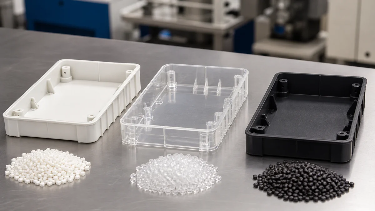
Start with the failure mode the part must avoid, not a belief that one resin is universally superior. ABS is often the practical baseline for housings, covers, and appearance-oriented parts under moderate service conditions. It generally offers favorable flow and supports common cosmetic finishing routes.
PC becomes relevant when the design has a documented need for transparency, sustained heat performance, or resistance to substantial impact. Those benefits come with a more demanding molding window, particularly around moisture, flow, venting, and process stability. PC-ABS occupies the middle ground: it can offer more toughness and heat resistance than ABS while being less demanding to process than pure PC.
| Specification decision | ABS | PC | PC-ABS |
|---|---|---|---|
| Dominant selection reason | Processing economy and cosmetic finishing | Heat, impact, or transparency | Balanced toughness, heat performance, and moldability |
| Thin walls or long flow paths | Usually the easiest starting point | Requires the closest filling review | Intermediate flow demand |
| Moisture-control burden | Grade-specific control | Rigorous control is important | Controlled drying beyond ordinary ABS handling |
| Common approval risk | Understated service loads | Unjustified premium substitution | Undefined blend grade or additives |
Example: A painted equipment cover with moderate loads may gain little from pure PC. ABS is the cleaner starting point, while PC-ABS deserves review if clips or screw bosses experience repeated assembly stress. The approval package should identify the exact resin grade, color, additives, operating environment, wall geometry, and production intent. A reliable material selection framework1 uses those inputs together rather than ranking the three families as good, better, and best.
What Process Does Plastic Injection Molding Use?
Plastic injection molding heats a specified polymer, injects it into a mold cavity, packs the material, cools the formed part, and ejects it. It is a mold-based polymer process and must not be confused with machining, sheet metal punching, fabrication, or die stamping.
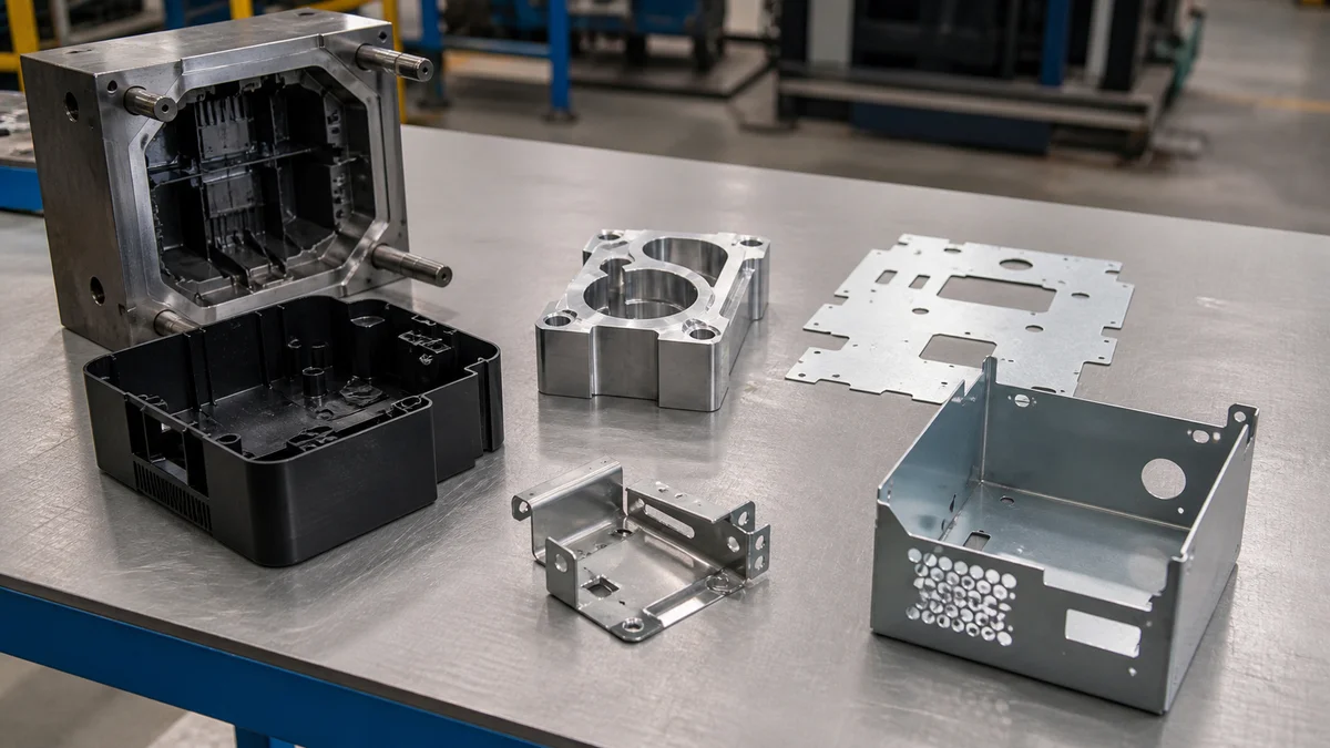
Injection molding converts resin pellets into a part through a controlled fill, pack, cool, and eject sequence. The mold establishes the cavity geometry, but the delivered shape also responds to resin shrinkage, flow direction, packing, cooling, gate location, venting, and ejection. Precise mold machining therefore does not guarantee identical behavior for every molded dimension.
Before quotation, use correct manufacturing process terminology2:
- Plastic injection molding fills a dedicated mold with molten polymer and ejects the cooled part.
- CNC machining removes material from solid stock by milling, turning, drilling, boring, reaming, or related cutting operations.
- CNC turret punching uses programmed punch tools to cut or form sheet metal.
- Metal stamping cuts or forms sheet metal with dedicated dies.
- Sheet metal fabrication may combine cutting, punching, bending, welding, assembly, and finishing.
These processes are not interchangeable. They impose different geometry rules, tooling commitments, tolerance behavior, inspection needs, and production economics. A molding drawing should address wall thickness, draft, gates, parting, cooling, and ejection—not burr direction, springback, or cutter access, which belong to different processes.
“CNC turret punching, CNC punch press, CNC-controlled stamping equipment, or metal stamping depending on the actual process” is not one standard term. If it appears in a drawing or purchase request, clarify whether it means CNC turret punching, a CNC punch press, CNC-controlled stamping equipment, sheet metal fabrication, or die stamping. For this comparison, the required process is plastic injection molding. Naming it correctly prevents a supplier from quoting the wrong route or applying metalworking assumptions to a polymer component.
How Does Each Resin Change the Molding Process Window?
Processing generally becomes more demanding from ABS to PC-ABS and then PC. As resin demand increases, drying, temperature control, pressure, venting, flow management, and process stability require closer attention. The exact grade and additives must guide the molding plan rather than the family name alone.
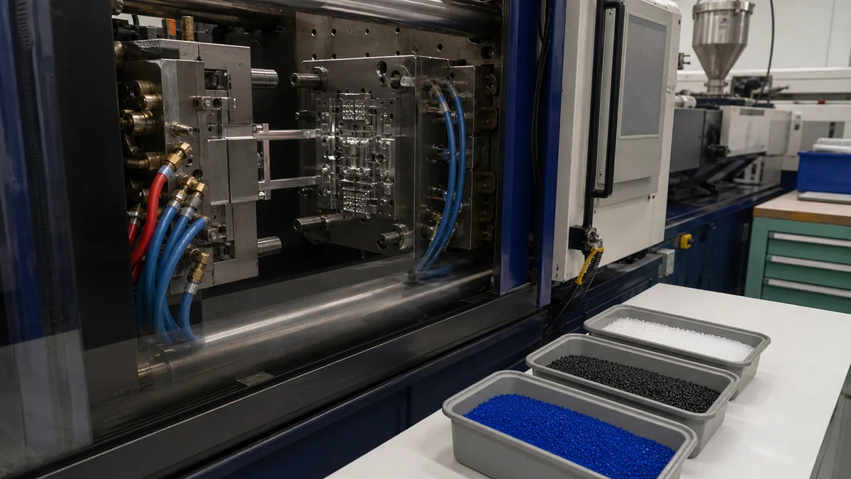
ABS usually provides the most forgiving starting point for conventional molded geometry. PC has greater flow resistance and typically needs more disciplined control of temperature, moisture, injection pressure, and venting. PC-ABS commonly falls between them, although blends carrying the same family name can behave differently.
| Process input | ABS | PC-ABS | PC | Quotation consequence |
|---|---|---|---|---|
| Relative flow demand | Lower | Intermediate | Higher | Influences gate, wall, and pressure review |
| Thermal demand | Generally lower | Intermediate | Generally higher | Affects mold and process planning |
| Drying sensitivity | Grade-controlled | Significant | Particularly important | Changes handling and conditioning scope |
| Venting review | Required | Closer review | Most demanding review | Influences end-of-fill stability |
| Substitution risk | Moderate | High because blends vary | High with optical grades or additives | May trigger renewed samples and validation |
These are comparison directions, not universal machine settings. Melt and mold conditions, injection profile, packing, cooling, and drying must follow the selected grade and actual geometry. Additives for color, ultraviolet exposure, impact modification, or flame performance can alter flow and processing behavior.
The mold review should connect the resin to gate size and location, vent placement, wall transitions, end-of-fill regions, cooling balance, and ejection. A long flow path ending in a thin cosmetic wall presents a different risk from a compact housing with uniform sections. The production plan should explain how a stable injection molding process window3 will be developed and what evidence sample approval requires.
Treating PC as a drop-in replacement for ABS after mold construction can create filling, appearance, dimensional, or cycle-development problems absent from the original plan. A material change should therefore trigger a controlled review of the resin, mold, process, and acceptance requirements.
What Drying Controls Should the Resin Specification Require?
Specify the exact resin grade, approved storage and handling conditions, required conditioning records, and the cosmetic or mechanical risks tied to moisture. PC needs rigorous drying control, PC-ABS also requires controlled conditioning, and ABS should still follow the selected resin supplier’s instructions.
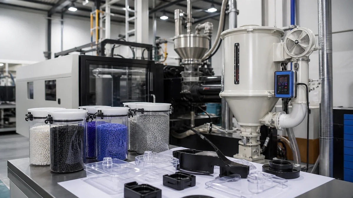
Drying belongs in material control, not in an informal machine-side preference. Moisture exposure can occur during transport, storage, open-container handling, material transfer, or a production interruption. The correct response depends on the exact grade, packaging history, additives, and resin supplier drying guidance4.
A useful material-control note addresses:
- Exact resin manufacturer and grade, or a controlled list of alternatives.
- Original packaging, resealing, storage, and transfer expectations.
- The grade-specific drying instruction governing production.
- Handling between the dryer and molding machine.
- Reconditioning after an interruption or prolonged exposure.
- Lot, drying, or conditioning records when traceability is required.
- Appearance-critical surfaces where splay or inconsistent gloss is unacceptable.
PC is hygroscopic and warrants the strongest moisture-control attention of the three. Inadequate conditioning can contribute to splay, hydrolytic degradation, and inconsistent appearance or performance. PC-ABS also needs controlled, grade-specific drying; the presence of ABS in the blend does not justify treating it as ordinary ABS. ABS generally presents a lighter burden, but its datasheet and storage history still govern.
Do not copy one drying temperature and duration across all ABS, PC, and PC-ABS grades. That instruction may conflict with the selected resin or ignore different exposure histories. The RFQ should define material identity, storage expectations, record requirements, and the surfaces or properties placed at risk by moisture. The molder can then propose a conditioning plan tied to the approved grade. This approach makes drying auditable without turning an unsupported generic setting into a contractual requirement.
Which Resin Best Fits Thin Walls and Long Flow Paths?
ABS is generally the least demanding option for thin walls and long flow paths, PC-ABS is intermediate, and PC requires the closest filling review. Material selection must consider wall thickness, flow distance, transitions, gates, vents, ribs, bosses, pressure demand, and cosmetic restrictions together.

Thin-wall feasibility cannot be judged from one nominal thickness. The relevant question is whether the selected resin can reach and pack every feature through the proposed gate arrangement before local sections freeze. Review how far the melt travels, where it divides around openings, where the fronts rejoin, and whether air can escape at the end of fill.
ABS often provides the most favorable starting point when thin walls coincide with longer flow. PC-ABS can remain practical but normally needs closer review of pressure demand and stability. PC’s higher viscosity makes the same geometry more demanding, so its finished-part advantages must be weighed against the actual filling route before tooling release.
A wall-thickness map should show minimum and maximum sections, abrupt transitions, ribs, bosses, clips, cosmetic faces, anticipated ends of fill, and acceptable weld-line regions. It should also identify gate restrictions. A cosmetically convenient no-gate zone can force a longer flow path, while a heavy boss near the end of fill may be difficult to pack consistently.
If PC is functionally necessary, revise the geometry before relying on additional process demand. Practical options include shortening the flow path, relocating or changing the gate, easing abrupt transitions, improving venting, or revising non-critical wall sections. A thin-wall molding design review5 should consider wall thickness, flow length, gate location, venting, cooling, and the exact resin as one system.
The supplier should confirm that the resin, mold concept, available processing envelope, and validation plan are compatible. Published material properties describe the finished resin; they do not prove that the proposed cavity can be filled, packed, cooled, and ejected consistently.
When Do Heat, Impact, or Assembly Loads Justify PC or PC-ABS?
Choose PC when documented sustained heat, substantial impact, or transparency requirements dominate. Consider PC-ABS when clips, bosses, brackets, or housings need greater toughness and heat performance than ABS with a less demanding molding window than PC. Replace vague labels with measurable service conditions.
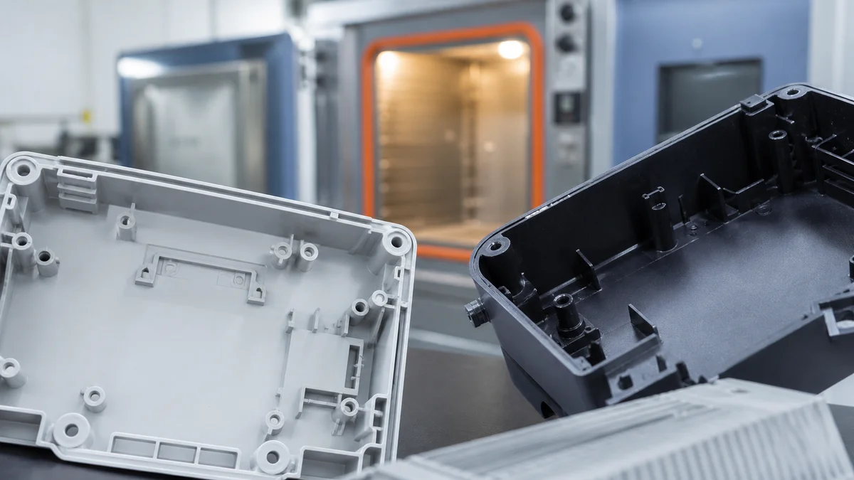
Specify heat resistance, impact performance, and assembly durability as separate requirements. “High impact” and “heat resistant” give the resin supplier and molder no defensible grade-selection basis. The operating environment, load direction, exposure duration, and likely failure location matter more than the broad resin family.
For heat exposure, state normal and exceptional operating temperatures, duration, nearby heat sources, ventilation, and load during exposure. Clarify whether the concern is dimensional movement, loss of retention, surface appearance, or another functional change. A short transient event is not equivalent to sustained service under load.
For impact, define the event: a drop, tool strike, repeated contact, transport shock, or deliberate abuse. Identify the impact location, direction, frequency, temperature condition, and acceptable failure mode. If transparency points toward PC, also define optical zones, surface finish, gate restrictions, flow-mark limits, and scratch expectations.
Assembly-load specifications should identify:
- Snap arms, clips, latches, screw bosses, press features, and loaded brackets.
- Assembly direction and expected assembly or service cycles.
- Fastener type, tightening control, inserts, and boss support where applicable.
- Likely stress concentrations and the consequence of cracking or permanent deformation.
ABS may remain suitable when these demands are moderate. PC-ABS often merits review for durable housings with clips or loaded fastening features. Pure PC should answer a documented service need because its harder processing window can add tooling and production risk without improving a part governed mainly by appearance. A clear service load specification6 lets the supplier compare exact grades without relying on headline property claims.
How Should Geometry Control Shrinkage, Sink, and Warpage?
Control sink and warpage through reasonably uniform walls, gradual transitions, properly proportioned ribs and bosses, balanced filling, packing, and cooling. Published shrinkage values overlap among these resins and cannot replace a grade-specific review of geometry, gates, residual stress, datums, and measurement conditions.
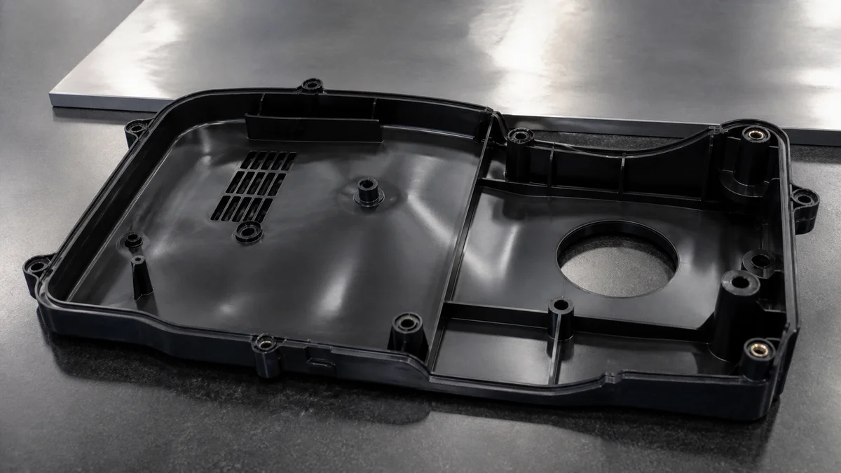
Shrinkage is not one material number that applies uniformly to every cavity dimension. The delivered geometry responds to grade, flow orientation, packing, cooling, wall section, gate location, and residual stress. Published ranges help with early comparison, but the toolmaker must develop the cavity allowance around the selected resin and process plan.
Before adding close tolerances, make the geometry support stable molding:
- Keep nominal walls reasonably uniform where function permits.
- Core out isolated heavy sections.
- Use gradual transitions between wall thicknesses.
- Review rib and boss junctions behind cosmetic faces.
- Support fastening loads without relying on solid boss mass.
- Coordinate gate location with packing and expected deformation.
- Identify broad faces needing measurable flatness, profile, or warpage control.
Scenario: Injection molded cover DFM. A cover has thick screw bosses attached directly to a broad visible wall, while adjacent walls are much thinner. The boss regions cool and contract differently, creating sink on the cosmetic face or pulling the cover out of shape. Changing from ABS to PC-ABS or PC does not correct the mass imbalance. Review cored bosses, supporting ribs, gradual transitions, gate influence, and cooling before steel is released.
The drawing should establish functional datums, critical mating dimensions, permitted warpage, and the inspection state. A free-state part may produce a different result from one restrained in an assembly fixture. If restraint is allowed during measurement, define it explicitly.
Good sink and warpage prevention7 treats geometry, filling, packing, cooling, and inspection as one system. Tightening every linear tolerance cannot compensate for a wall layout that cools unevenly or for acceptance criteria that leave the measurement condition undefined.
How Should Molded-Part Tolerances and Inspection Be Specified?
Apply close tolerances only to functional molded features, then define datums, conditioning time, measurement environment, sampling, reporting, and cavity traceability. Resin selection alone does not establish tolerance capability because shrinkage, cooling, residual stress, cavity position, geometry, and process stability all affect repeatability.

Separate functional dimensions from ordinary and cosmetic geometry. Mating interfaces, sealing areas, locating features, clips, screw bosses, and functional hole patterns may justify focused control. Clearance pockets, hidden surfaces, and non-contact edges usually do not need the same tolerance or inspection burden.
| Feature class | Drawing requirement | Inspection condition | Approval evidence |
|---|---|---|---|
| Mating or locating feature | Size, position, and datum relationship | Defined conditioning state | First-article values and planned sampling |
| Sealing interface | Profile, flatness, and relevant surface condition | Free state or specified fixture | Agreed dimensional report |
| Clip or screw boss | Fit, location, and assembly behavior | Stabilized part with stated test setup | Dimensions plus approved functional test |
| Cosmetic surface | Zone-specific visual criteria | Defined lighting and viewing conditions | Approved sample or documented inspection |
| Clearance geometry | Suitable general molded tolerance | Routine measurement state | Sampling unless risk requires more |
Use functional datums rather than dimensions chained from convenient edges. Chained locations can accumulate tolerance stack-up without protecting the mating relationship. Where warpage or feature location controls assembly, profile, flatness, or position may communicate the requirement more clearly than a narrow plus-or-minus dimension.
A molded part inspection plan8 should state when parts may be measured, the relevant environmental or conditioning state, and whether a fixture may restrain the component. For multi-cavity tooling, specify whether results must identify the producing cavity. Define first-article scope, production sampling, selected critical-feature checks, and recurring reports before quotation.
Inspection verifies output; it does not correct an unsuitable shrinkage allowance, uneven cooling, or an unstable process. Pairing each critical characteristic with a datum, measurement condition, method, and sampling expectation lets the supplier include mold development, process control, metrology, and reporting in one coherent plan.
Which Material Best Supports Transparency, Paint, Plating, or Cosmetic Surfaces?
Use PC as the primary candidate when true transparency is required, ABS when paintability and economical cosmetic molding dominate, and PC-ABS when appearance must accompany greater toughness. Specify the exact grade, color, texture, gloss, cosmetic zones, finishing route, weld-line limits, and witness-mark expectations.
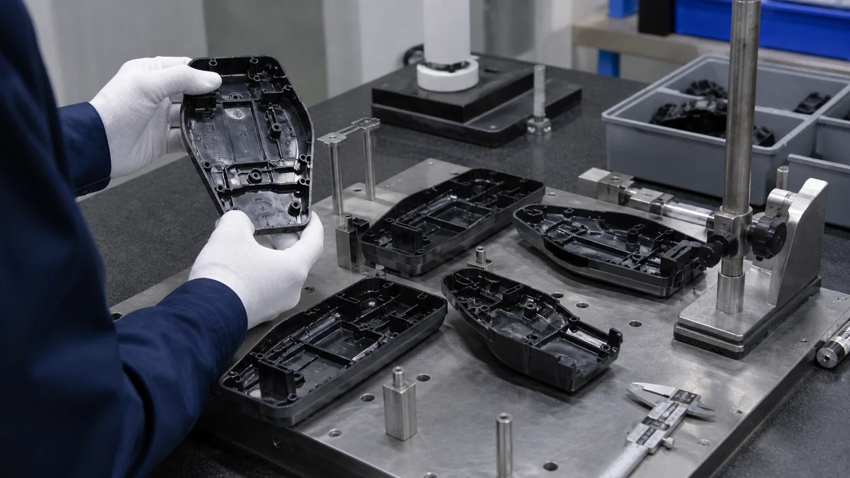
Cosmetic performance comes from the material, mold surface, process, and finishing route together. A resin family name does not guarantee gloss, texture replication, color consistency, or final appearance. Exact grade, additives, drying, gate position, flow behavior, cooling, and surface preparation all contribute.
| Visible requirement | Initial material direction | Controlled specification | Main approval risk |
|---|---|---|---|
| Transparent molded region | PC | Optical grade, optical zone, gate limits, surface condition | Splay, flow marks, or visible stress |
| Painted opaque housing | ABS | Paint system, preparation, color, texture | Poor preparation or visible sink |
| Tough painted enclosure | PC-ABS | Exact blend, drying, paint compatibility | Unapproved grade substitution |
| Plated appearance | Suitable ABS or PC-ABS grade | Approved resin and preparation route | Adhesion or inconsistent surface condition |
| Molded texture or gloss | Grade-dependent | Texture reference, draft, gloss, viewing method | Uneven replication or drag marks |
Mark A-surfaces, secondary visible faces, hidden zones, and functional interfaces on the drawing or cosmetic specification. Define the color reference, texture, gloss expectation, viewing conditions, and permitted locations for weld lines, gates, parting lines, and ejector witnesses. Draft must also suit the selected texture and pull direction; an appearance requirement that ignores ejection can produce drag or surface damage.
Paint, plating, texture, or polish is not a repair for unstable molding. Splay from poor conditioning, sink over heavy bosses, flow marks, weld lines, and gate vestiges may remain visible or become more obvious after finishing. Confirm resin finish compatibility9 before tool approval. When substitutions are allowed, request representative molded and finished samples under the proposed production route rather than assuming visual equivalence from the family name.
What Drives Total Cost and Lead Time Beyond Resin Price?
Total program cost depends on mold complexity, drying, thermal demand, flow difficulty, gates, vents, cooling, process development, cosmetics, validation, inspection, scrap exposure, and finishing—not resin price alone. Quantity, annual demand, revision stability, cavity strategy, and delivery expectations also influence the appropriate material and tooling plan.
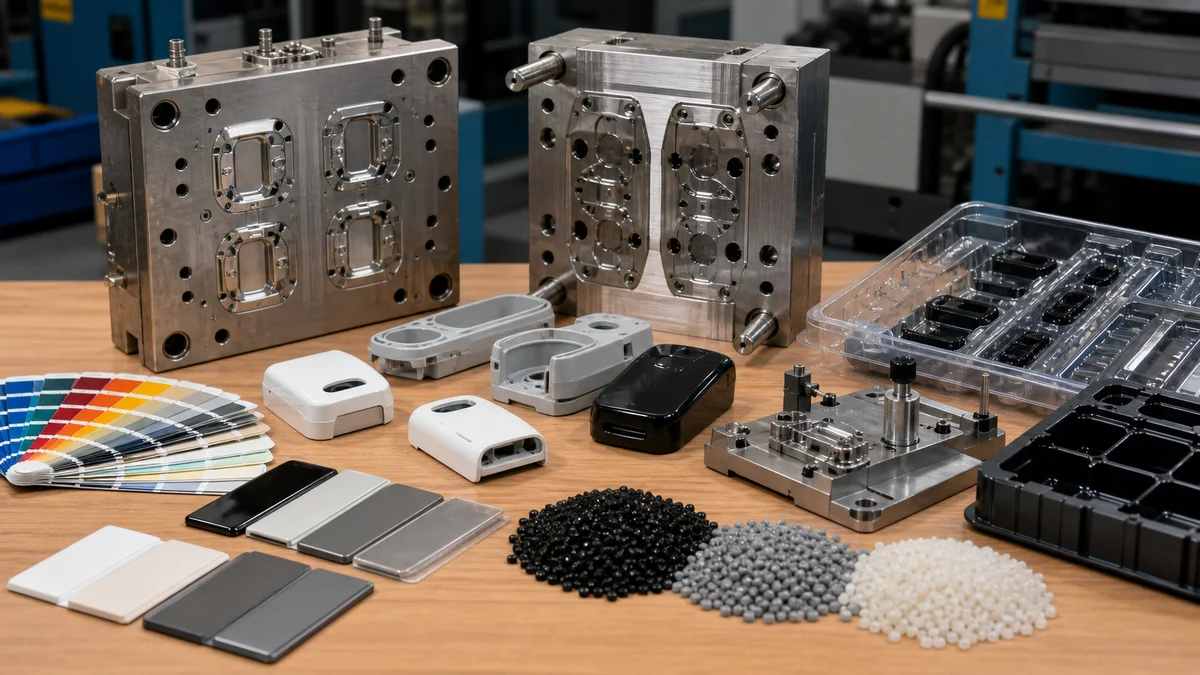
Raw-resin price is visible, but it may not be the dominant difference between delivered-part quotations. ABS can reduce processing burden through easier flow and lower thermal demand. PC may require stronger drying control, greater thermal and pressure capability, closer venting review, and more development work. PC-ABS often sits between them, depending on the formulation.
Build a total program cost comparison10 around the assumptions that actually change the manufacturing route:
- Exact resin grade, color, additives, sourcing basis, and alternatives.
- Drying, storage, transfer, regrind, and traceability requirements.
- Wall distribution, flow length, gates, vents, and cooling strategy.
- Mold construction, cavity count, slides, lifters, inserts, and change parts.
- Sample iterations, dimensional validation, cosmetic approval, and functional tests.
- Painting, plating, printing, assembly, trimming, packaging, or other secondary work.
- Inspection frequency, cavity-specific results, and documentation.
- Scrap exposure from cosmetic restrictions or narrowly controlled dimensions.
- Immediate quantity, batch size, annual demand, and expected program duration.
- Revision stability, tooling ownership, and responsibility for changes.
Compare schedule across material procurement, tool design, mold construction, sampling, correction, approval, and production. Avoid treating one unsupported headline lead time as the complete program plan. A late resin change can alter shrinkage allowance, gates, venting, processing conditions, cosmetics, and sample approval.
Request alternatives for ABS, PC, and PC-ABS only when each could meet the service requirement. Suppliers should quote the same geometry, demand, finish, inspection scope, and delivery expectations. Otherwise, an apparently cheaper material may simply reflect omitted validation, secondary finishing, or quality requirements rather than a genuinely lower delivered cost.
Which Material-Selection Mistakes Create the Most Tooling Risk?
The largest tooling risks come from choosing PC as an unsupported premium upgrade, retaining ABS despite documented service loads, or specifying PC-ABS without an exact grade. Material choice must be reviewed with filling, shrinkage, assembly stress, cosmetics, inspection, and revision risk before mold construction begins.
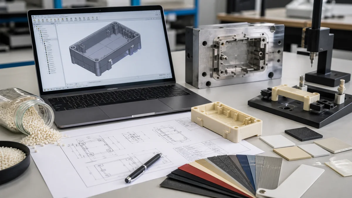
Material mistakes become tooling risks when they invalidate assumptions used to size gates, establish shrinkage allowance, design vents and cooling, place cosmetic witnesses, or approve molded dimensions. Once steel is cut, changing resin may require more than adjusting machine settings.
Watch for these predictable specification failures:
- Selecting PC because it sounds superior without documenting heat, impact, or transparency requirements.
- Retaining ABS where clips, bosses, or service exposure need greater toughness.
- Calling out only “PC-ABS” without a grade, additives, color, or approval path for substitutions.
- Approving thin walls and long flow paths from finished-part properties alone.
- Treating a published shrinkage value as proof of dimensional repeatability.
- Expecting paint, plating, or texture to hide splay, sink, weld lines, or flow instability.
- Applying close tolerances everywhere without functional datums or an inspection plan.
Example: A housing and its mold concept are developed around ABS. Late in approval, PC is requested as a general quality upgrade, although the heat, impact, and transparency requirements have not changed. The substitution can affect flow, drying, pressure demand, venting, shrinkage behavior, and cosmetic development. It should trigger a formal resin change review11 rather than an informal material swap.
Ask one direct approval question: what credible failure mode does this resin prevent? The answer should connect to service temperature, impact, assembly stress, appearance, or transparency, then be tested against geometry and molding risk. Material choice cannot substitute for sound wall design, practical gates and vents, stable cooling, localized tolerances, or defined inspection. The strongest specification is the one that links the selected grade to a documented need and preserves controlled alternatives where engineering permits them.
What Should an ABS, PC, or PC-ABS Injection Molding RFQ Include?
A complete RFQ must define the controlled geometry, exact resin or approved alternatives, demand, service conditions, functional tolerances, cosmetics, wall distribution, gate restrictions, inspection, sample approval, revision, and delivery expectations. The 3D model and 2D drawing should agree or clearly identify which document governs.

Use this injection molding RFQ checklist12 before requesting a material recommendation, mold quotation, or molded sample. Missing inputs force suppliers to assume performance, tooling scope, validation effort, or commercial risk.
Geometry and document control
- ☐ Native or neutral 3D model showing complete geometry.
- ☐ Controlled 2D drawing with units, part number, and active revision.
- ☐ Governing-document statement if the model and drawing conflict.
- ☐ Wall-thickness map covering ribs, bosses, clips, undercuts, and transitions.
- ☐ Draft direction, textured walls, and any interfaces that restrict draft.
- ☐ Preferred and prohibited gate, parting-line, and ejector-witness zones.
Material and service conditions
- ☐ Preferred ABS, PC, or PC-ABS manufacturer and grade.
- ☐ Approved alternatives or a requirement for substitution approval.
- ☐ Color, additives, filler content, transparency, and any applicable flame requirement.
- ☐ Operating-temperature range, duration, impact scenario, and load direction.
- ☐ Assembly cycles, chemicals, cleaning, and environmental exposure.
- ☐ Storage, drying, conditioning, traceability, and regrind restrictions.
Quality and appearance
- ☐ Functional datums and critical tolerances separated from ordinary geometry.
- ☐ Flatness, profile, or warpage criteria where assembly requires them.
- ☐ Surface finish, texture, gloss, cosmetic zones, weld-line limits, paint, or plating.
- ☐ Measurement condition, stabilization period, and permitted restraint.
- ☐ First-article scope, production sampling, reports, and cavity traceability.
- ☐ Sample-approval criteria and any defined functional tests.
Commercial and production intent
- ☐ Prototype, pilot, bridge, or repeat-production intent.
- ☐ Immediate quantity, batch size, annual demand, and forecast confidence.
- ☐ Expected revisions, tooling ownership, and change-approval responsibility.
- ☐ Delivery expectations and any staged shipment needs.
A complete package allows molders to compare material, tooling, processing, validation, and quality assumptions on the same basis.
For a material recommendation, sample plan, or quotation, send the 3D model, controlled 2D drawing, exact resin grade or approved alternatives, quantity, prototype or production intent, critical tolerances, surface finish and cosmetic zones, inspection expectations, active revision, service conditions, and delivery requirements.
References
-
PC/ABS Alloy Guide: Properties, Applications & Processing - This comprehensive guide covers PC ABS Alloy's composition, key properties, and real-world applications. of polycarbonate (PC) ↩
-
CNC Machining vs Stamping: Which Is Best for Your Project? - In many cases, we also implement hybrid manufacturing, where we combine soft tooling, laser cutting, or turret punching with selective forming or CNC finishing. ↩
-
Polycarbonate Injection Molding Guide: Everything You Need ... - Recommended Processing Parameters for PC Injection Molding. Processing PC requires a tight window, but once established it is remarkably stable. ↩
-
PC/ABS Drying Guide: Moisture Control Before Molding - Learn PC/ABS drying conditions, moisture limits, and best practices to prevent defects and improve injection molding stability. ↩
-
Thin-Wall Injection Molding: Design & Process Guide - Flow length is as important as wall thickness. A long, thin path may require a different resin grade, gate location, runner, or number of gates ... ↩
-
PC/ABS Resin: Durable, Versatile & High-Performance - Exceptional Impact Strength · High Heat Resistance · Excellent Processability · Superior Aesthetics and Surface Quality · Good Dimensional Stability. ↩
-
Designing Bosses For Injection Molding: A Complete Guide - Master boss design for injection molding with our complete guide. Learn key rules for wall thickness, height, ribs, and spacing to prevent ... ↩
-
The Ultimate Guide to Injection Molding Tolerances - To maintain part tolerances, injection molds must provide consistent, repeatable heating and cooling. Mold makers need to place cooling channels with care ↩
-
ABS Plastic Injection Molding: Grades, Parameters & Defects - ABS plastic injection molding guide from a 30-year OEM family workshop: grades, processing parameters, common defects, and when ABS isn't the right ... ↩
-
Optimizing Injection Molding Tooling for Cost and ... - Discover how to balance cost, speed, and performance in injection molding tooling strategies for optimal manufacturing efficiency and ... ↩
-
Injection Molding Tool Validation | Mold Acceptance, CMM ... - The mold should be validated within the agreed press tonnage, injection capacity, mold temperature range, cooling setup, resin condition, and process window. ↩
-
Plastic Injection Molding RFQ Checklist for Quote-Ready ... - A quote-ready plastic injection molding RFQ should include 3D CAD, a 2D drawing with CTQ and datum references, resin grade, tolerance requirements, annual ... ↩