
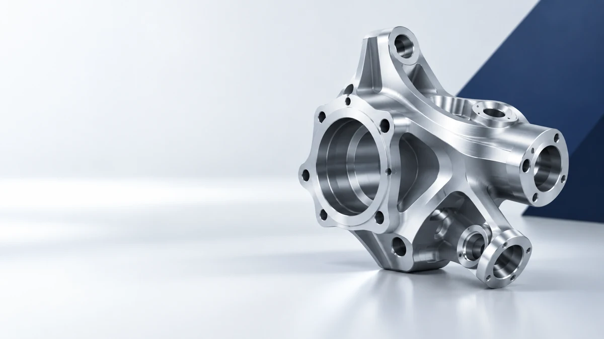
China 5-Axis CNC Machining Service
Let the part geometry decide whether a 5-axis route is justified. Send the complete CAD and mark the angled features, critical face relationships and surfaces a conventional setup cannot reach.
- Mark the surfaces and holes that must stay related after machining.
- Separate cosmetic freeform surfaces from controlled functional geometry.
- Share the material, quantity and inspection condition with the model.
- In-house production
- ISO 9001
- 24h quote response
- 80+ countries
What to check before a 5-axis quote
Jump to the route, access or verification question that is holding up your project.
5-Axis Parts
Part patterns worth a 5-axis review
When 5-Axis Helps
Three conditions that justify the route
Multi-Face Access
Angled bores, recesses and blocked faces
Complex Surfaces
Profile control versus appearance
Setup Strategy
Clamping, datums and transfer points
Materials and Finishes
Grade, coating and polishing effects
5-Axis Production
Machined and inspected in-house
Inspection Plan
Angled features and surface records
Quote Inputs
What to send for a firm quote
5-Axis FAQ
Ten questions buyers ask first
Request a Quote
Send your model to Parker
Parts that may need 5-axis
Consider five-axis machining for a feature relationship, not for the look of complexity. A multi-face housing, angled manifold or contoured part may benefit when cutter access and datum transfer create a specific problem.
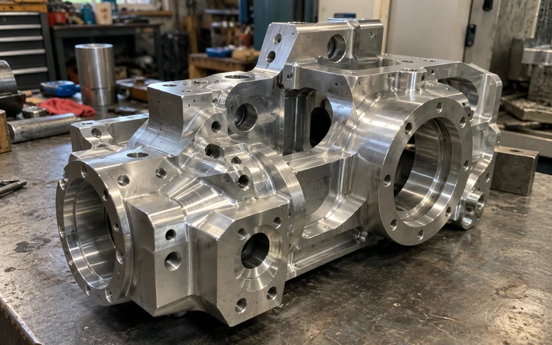
Multi-face component
Document which holes and faces must relate to one datum system, and which can be checked on their own.
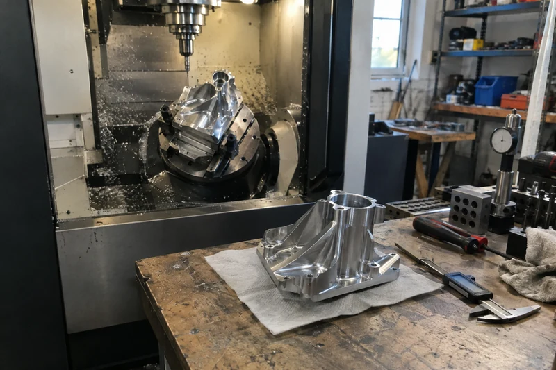
Angled passage or port
Document the tool direction that reaches the full functional feature, not only its entry.
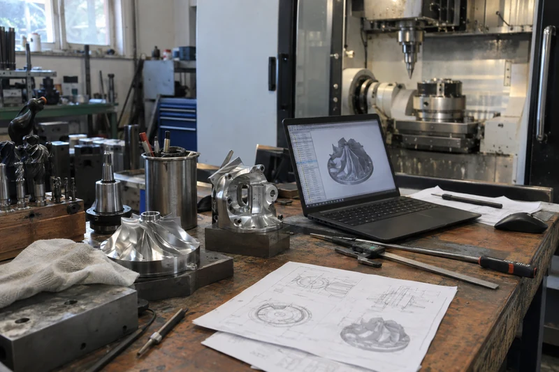
Contoured surface
Document whether the surface is controlled by profile, by finish or by appearance alone.
A visually intricate part whose features are all reachable may still suit a simpler route, such as CNC milling in conventional setups. To compare machining routes in general, see CNC machining.
Quote response within 24 hours for complete drawings.
When a 5-axis route helps
Compare the possible tool approaches before you name a machine. Three conditions justify a five-axis review; if none applies, a simpler setup is usually the better route.
Indexing the part between fixed orientations, known as 3+2, solves some multi-face work. Continuous coordinated motion serves a different set of geometry and surface requirements.
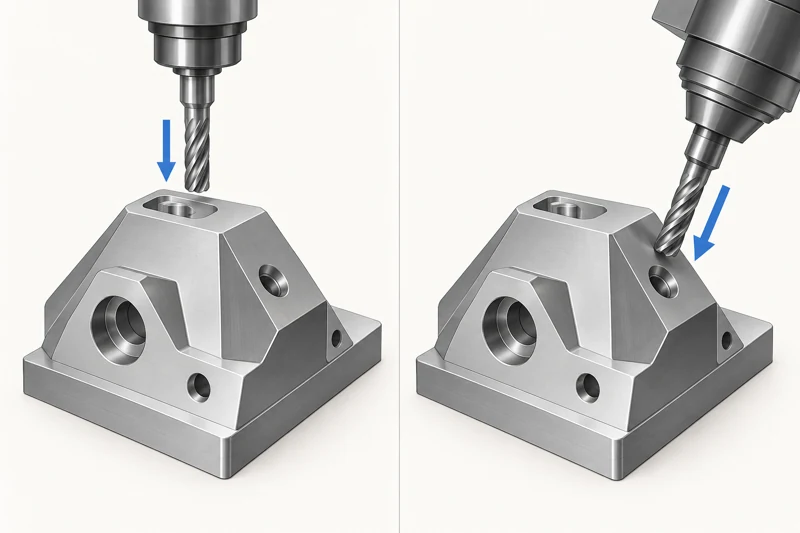
A feature is out of reach
The feature cannot be reached reliably from a practical three-axis orientation.
A relationship is at risk
Repeated repositioning would threaten a critical relationship between faces or holes.
The tool angle matters
A surface needs the tool held at a controlled orientation to its profile.
None of these conditions creates a tighter tolerance by itself; tolerance-driven parts are covered under precision machining. If a simpler setup reaches every controlled feature, your quote should explain why the extra axis motion is unnecessary.
Multi-face access
Access is limited by the cutter, the holder and nearby geometry, not by whether a face is visible in CAD. Mark the recesses, angled bores and obstructed surfaces that must be machined rather than left as cast, molded or unfinished.
Highlight any collision area in the CAD model. The toolpath and fixture are then confirmed during the route review for your part.
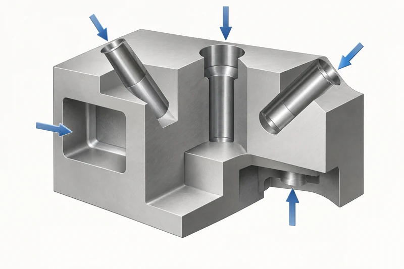
| Feature | Review input | Possible constraint |
|---|---|---|
| Angled bore | Direction, depth, relation to the adjacent face | Holder clearance and entry angle |
| Recessed pocket | Opening, floor, wall and corner requirement | Tool reach and collision |
| Opposing faces | Controlled distance and common datum | Repositioning and inspection |
| Obstructed surface | Required finish or profile zone | Unreachable area after fixturing |
Review input Direction, depth, relation to the adjacent face
Possible constraint Holder clearance and entry angle
Review input Opening, floor, wall and corner requirement
Possible constraint Tool reach and collision
Review input Controlled distance and common datum
Possible constraint Repositioning and inspection
Review input Required finish or profile zone
Possible constraint Unreachable area after fixturing
Not sure a feature can be reached? Mark it in the model and ask for an access review.
Complex surfaces: shape or appearance
Separate shape control from appearance. A sealing or mating surface needs a defined profile, datum scheme and inspection method, while a blended exterior may only need a visual reference.
Controlled surfaces
- The CAD revision that serves as the geometric reference.
- The zones where profile, edge transition or surface condition matters.
- The datum scheme for each sealing or mating surface.
- How measured points, scan data or another method are compared with the model.
Cosmetic surfaces
- A visual reference or reference sample for blended exterior areas.
- The viewed area the appearance criteria apply to.
- A visual approval kept separate from the profile record.
Do not put a tight general tolerance on the whole model when only a few contact regions govern function. The comparison method and the record are agreed for your part before production starts.
Setup strategy and datum transfer
Fewer setups can reduce datum transfer, but setup count alone guarantees nothing. What matters is whether the holding strategy keeps the functional relationships while the required faces stay reachable.
The choice between 3+2 positioning, continuous five-axis motion and several conventional setups follows your drawing and the route confirmed in your quote.
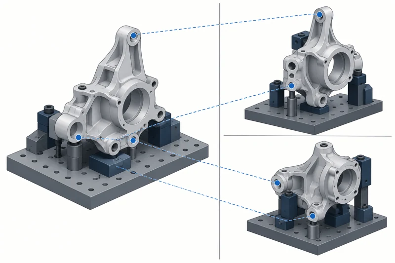
Clamping surfaces
Show which surfaces can be clamped, so the fixture holds the part without covering a face that must be machined.
No-mark surfaces
Mark the surfaces that cannot carry clamp marks, such as sealing faces or visible areas.
Datums after repositioning
Name the datum features that must stay accessible after the part is moved to its next orientation.
Transfer and inspection point
Where a part needs more than one setup, the route names the controlled transfer and the point at which inspection happens.
Materials and finishes
Material condition affects workholding, tool access and how a complex surface is finished. Give the specified grade, heat-treatment state and any acceptable alternative before the route is priced.
Grade and condition
State the grade and heat-treatment state, and whether an alternative grade may be discussed before quoting.
Coatings
A coating can change a mating dimension. Say whether final dimensions apply after finishing and which areas are masked.
Polishing
Polishing can alter a profile or an edge. Mark the surfaces to polish and those to leave as machined.
Finishing runs in our own factory as well, and the finishing route is confirmed for each order.
Ask for the route, not a machine label
A machine name says little about how your controlled features will be delivered. Your quote covers the whole route instead: setups, workholding, secondary steps and final inspection, all in our own factory.
Production route in one factory
We machine and inspect your part in our own factory, so one team owns the result from drawing to shipment. Your quote names the route, from the setup strategy to the final check.
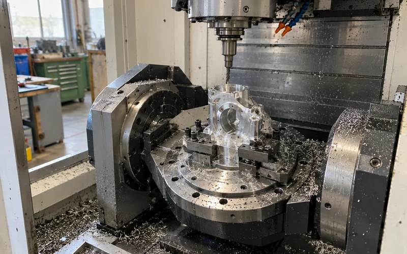
Route and setup
Your quote states whether your part runs on 3+2 positioning, continuous motion or conventional setups.
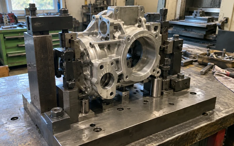
Fixture and datums
Ask how the part is held for multi-face access and which datum carries through each setup.
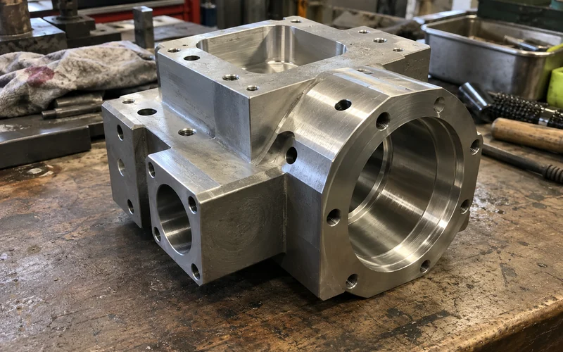
Finished part
We inspect the finished part in our own factory. Approve a sample against your drawing before volume production.
Sample sign-off before production.
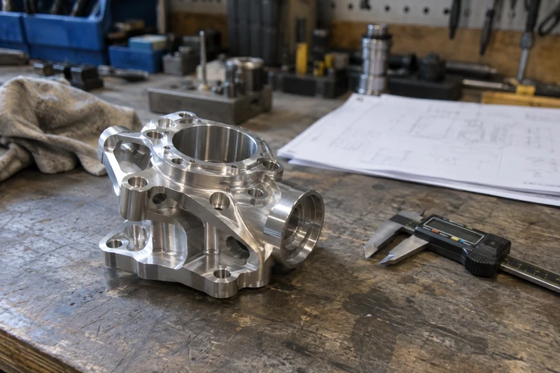
Inspect the features that justified the route
Build acceptance around the feature relationship that justified the route. For multi-face parts, record datum locations and the position of angled features; for controlled surfaces, specify the comparison basis and the area the report covers.
List the report you need in the RFQ. Final inspection runs in our own factory, and the method and record are agreed for each order.
| Requirement | Define on the drawing | Record to agree |
|---|---|---|
| Angled hole or face | Position and orientation to datums | Feature measurement and setup |
| Freeform profile | CAD revision, zone and tolerance | Surface comparison method and result |
| Mating face | Flatness or position as function requires | Agreed measured features |
| Appearance | Reference sample and viewed area | Separate visual approval |
Define on the drawing Position and orientation to datums
Record to agree Feature measurement and setup
Define on the drawing CAD revision, zone and tolerance
Record to agree Surface comparison method and result
Define on the drawing Flatness or position as function requires
Record to agree Agreed measured features
Define on the drawing Reference sample and viewed area
Record to agree Separate visual approval
What to send for a 5-axis quote
Send the complete model, not a screenshot of the difficult feature. The surrounding geometry decides tool access, fixturing and whether a simpler route can be proposed.
Include first
- Native or neutral 3D CAD and the current 2D drawing revision.
- Material grade and condition, quantity and order stage.
- Datum surfaces, controlled hole or face relationships and no-contact areas.
- Profile or appearance criteria for complex surfaces.
- Finishing, inspection report and delivery requirements.
Helpful additions
- An assembly model or mating component for an angled interface.
- Previous route problems, collision screenshots or rejected samples.
- Any supplied fixture, blank or CAM data, labeled as reference.
Quote response within 24 hours for complete drawings.
5-axis CNC machining FAQ
Short answers to the questions that usually come up before a 5-axis quote.
How does 3+2 machining differ from simultaneous five-axis motion?
In 3+2, the part or tool is positioned at an angle and then cut with a fixed orientation. Simultaneous motion changes the orientation during cutting. The geometry and the approved route decide which fits your part.
Does every multi-face part need five-axis machining?
No. Reachable faces can be machined in conventional setups if the required datum relationships can be kept and inspected. Share the model so the alternatives can be compared.
Can an undercut still be inaccessible on a five-axis machine?
Yes. Nearby walls, the cutter holder or the workholding can block the approach. Mark the full controlled surface and the geometry around it, not only the undercut.
Can a complex surface be accepted with calipers alone?
Usually not. A controlled freeform profile needs a comparison method that covers the specified area. Define the CAD reference, datums and acceptance zone before choosing the measurement approach.
Does five-axis motion make every dimension more accurate?
No. Accuracy depends on the part, setup, machine condition, toolpath and inspection method. The route can reduce some repositioning risks, but it is not a universal tolerance promise.
When should holes and faces stay in one setup?
When their positional relationship is critical and a datum transfer would add avoidable uncertainty. Show that relationship on the drawing so the setup can be evaluated.
Should a quote name a machine or explain the whole route?
The whole route. Your quote covers workholding, secondary steps and final inspection, all run in our own factory. A machine label alone does not explain how the controlled features will be delivered.
Is a supplied CAM program enough to define the job?
No. The current model, drawing, material and acceptance criteria remain the controlling inputs. A supplied program can only be reviewed against the actual equipment and the approved process.
How should surface appearance and profile be approved separately?
Define a visual reference for appearance and a measured zone and method for profile. Keep the two acceptance records separate; one cannot stand in for the other.
Who inspects a part machined by an external five-axis partner?
There is no external partner. We machine and inspect your part in our own factory, so one team is responsible for both; specify the features and records you need in the RFQ.
Request a 5-axis machining quote
Send the full model and tell us which features must stay related. Parker reviews it and replies with questions or a quote.

Parker
Your 5-Axis CNC Machining Contact, HONGYI
I'm Parker. Send the full CAD model and show the angled features, complex surfaces and datum relationships you need preserved. Add the material, quantity and the stage of your project.
Tell me where conventional setups have failed or why you think five-axis motion is needed. The review compares that route with simpler options, and your part is then machined and inspected in our own factory.
- Reply within 24 hours
- In-house production
- Drawings kept confidential