

China Overmolding Service
An overmolded part is a substrate plus a second molded layer, and it works only when the interface, material pair and acceptance test match its function. Start your RFQ with the complete part, not only the soft outer surface.
- Send the substrate drawing and mark the overmold region.
- Name the candidate materials, use environment and target volume.
- State the bond or retention behavior, and whether you supply the substrate or we mold it.
- In-house production
- ISO 9001
- 24h quote response
- 80+ countries
What to define before an overmolding quote
Jump to the material, interface or validation question you need to settle first.
Overmolded Parts
What the added layer must do
Material Pairing
Both grades and the use environment
Interface Design
Edges, recesses and retention geometry
Bond and Retention
Which test proves the interface
Tooling Strategy
Substrate source, tools and ownership
Overmolding Production
Control from substrate to finished part
Appearance and Flash
Visible edges, color and flash zones
Validation Plan
Tests, samples and reference records
Quote Inputs
One revision-controlled package
Overmolding FAQ
Ten questions buyers ask first
Request a Quote
Send your overmolding RFQ to Parker
Overmolded parts start with the layer's job
Define what the added layer must do: grip, cushion, seal, insulate or finish a visible surface. Each role changes the interface requirements and the test plan.
Identify the substrate material and geometry, the areas to cover and any faces that must stay free of overmold. Mark assembly contacts, touch surfaces and sealing paths on the drawing. If you supply the substrate, include its tolerance, surface condition and traceability requirement.

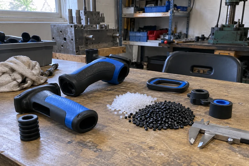
Grip or cushion
A grip can fail by peeling at its edge. Mark the touch surfaces and the load direction the layer has to survive.
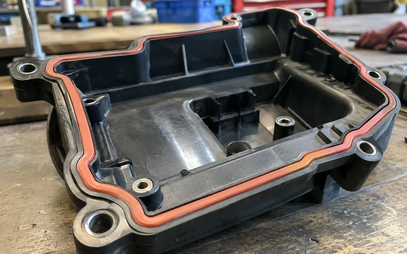
Seal
A seal can fail while it still looks intact. Mark the complete sealing path and the compression it has to hold.
Cosmetic or insulating layer
A visible layer can be rejected for color or flash even when retention is fine. Mark the visible faces and color boundaries.
This page covers the interface between a substrate and a molded layer. For a single-material plastic part, see plastic injection molding. If plastic is molded around a discrete metal or electronic component placed in the mold, that is insert molding.
Next, pin down both materials.
Material pairing, grade by grade
Material compatibility cannot be read from the word TPE alone. Substrate grade, elastomer grade, additives, surface condition and processing history all influence adhesion and appearance.
With the pair defined, the next question is the geometry that joins them.
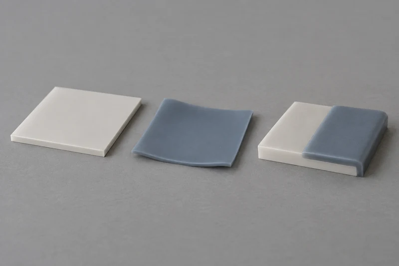
Name both grades
Send the actual grade, or a controlled performance specification, for the substrate and for the overmold material.
Fix what is fixed
If one material is already set by your design or approvals, say so before tooling decisions are locked.
Describe the environment
Temperature cycles, cleaning chemicals, UV exposure, oils and repeated flexing can change the interface over time.
Make grip feel testable
Specify the feel and durability of a grip with approved reference samples and measurable tests where possible.
Describe the seal load
For a seal, give the compression and leak conditions rather than asking for a soft material.
Design an interface that holds
The interface needs enough contact area, a controlled edge and a substrate that can survive the second molding cycle. Settle the points below in design review, before the tool is cut.
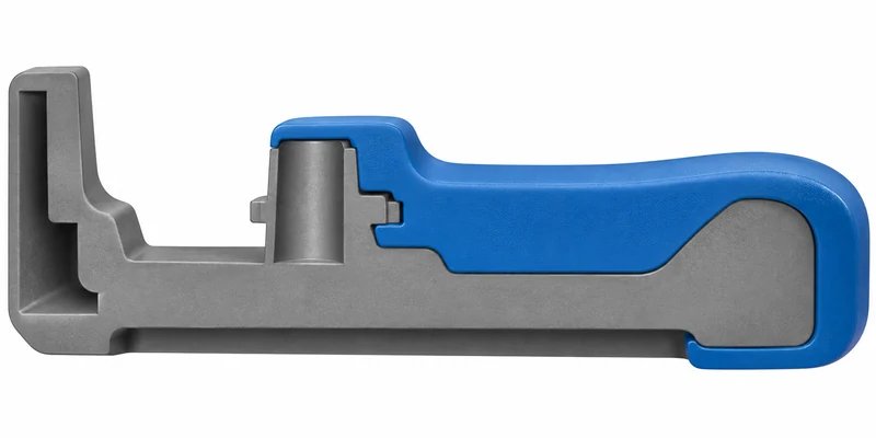
Where adhesion is uncertain or the part carries load, geometry can hold the second material physically: through-holes, undercuts or wrapped edges. Check each one against tool release, appearance and cleaning requirements.
| Feature | Risk | Define in design review |
|---|---|---|
| Thin overmold edge | Lifts or flashes | Shutoff surface and edge thickness |
| Deep recess | Traps air | Recess geometry and overmold thickness |
| Unsupported substrate wall | Distorts in the second cycle | Wall support and substrate material |
| Holes, ribs and corners | Uneven transitions | Overmold transitions around each feature |
| Mechanical lock | Must still release from the tool | Lock type, release, appearance and cleaning |
Risk Lifts or flashes
Define in design review Shutoff surface and edge thickness
Risk Traps air
Define in design review Recess geometry and overmold thickness
Risk Distorts in the second cycle
Define in design review Wall support and substrate material
Risk Uneven transitions
Define in design review Overmold transitions around each feature
Risk Must still release from the tool
Define in design review Lock type, release, appearance and cleaning
Retention geometry is a design option, not a substitute for a compatible material pair.
Not sure the edge will hold? Send the model and ask for an interface review.
Retention proven by test
State how the interface will be judged. Peel, pull, torque, compression and leak tests each measure a different failure mode, and a visual check alone cannot show long-term retention.

Choose the test
- Match the test to the part's function and the direction of expected load.
- Peel, pull, torque, compression or leak: pick the failure mode that matters in use.
- For a mechanical lock, test the complete assembly under use conditions, not only the polymer bond.
- If a material supplier recommends a pair, confirm it with your actual substrate grade, surface and process.
Set before the trial
- Sample preparation.
- Test condition.
- Acceptance threshold.
- Allowed failure mode.
Substrate, tools and overmold in one factory
We can mold the substrate, build both tools and run the overmold shot in our own factory, or overmold a substrate you supply. Tell us which, and who should own each tool. That one answer shapes the tooling route, production control and scrap terms in the sections that follow.
Tooling follows the substrate
Tooling depends on whether the substrate is molded in the same project or arrives as a finished component. Do not assume the routes are interchangeable from a photo of the finished part.
A different multi-shot approach can change the equipment and transfer requirements. We build and trial each tool in our own factory, and your quote states the tooling route for your part and who owns each tool.

Overmolding production starts before the shot
Substrate dimensions, cleanliness, moisture, storage and handling can affect the bond and placement. Every operation runs in our own factory, so one team controls the substrate, the shot and the finished part.
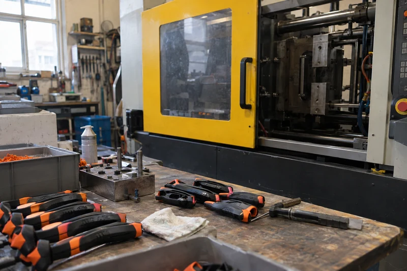
Incoming substrate
Define acceptance for incoming substrates: dimensions, cleanliness and surface condition.
Storage and traceability
Agree moisture control, storage, handling and lot traceability before the first production run.
Overmold shot
The process has to hold substrate location, coverage and interface quality on every part.
Change control
A change that improves appearance can alter the bond, so tie every change to a validated sample and revision.
Parts lost in trials
State in the quote how substrates lost in trials or production are counted and replaced.
Flash-free zones on the drawing
Mark visible surfaces, color boundaries and flash-free zones on the drawing, and define acceptable edge variation with a reference sample or a controlled visual standard.
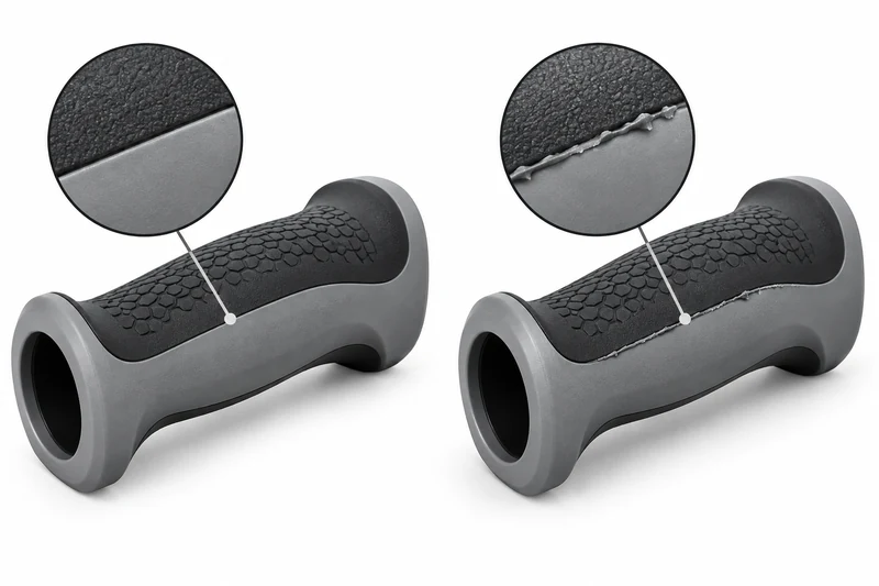
Judge by location
A minor edge defect in a hidden area may be tolerable, while the same defect on a grip or seal affects touch or function.
Test critical seals
Inspect the complete sealing path and test the assembly under the conditions you specify.
Control color and rework
Define the approved color master, lighting and lot comparison method, and whether rework is allowed and how it is verified.
Then tie every check into one validation plan.
A validation plan agreed before trials
Validation ties the drawing, the use environment and the failure mode together. When exposure matters, test after a defined conditioning cycle as well as at first sample approval.
Which tests are run, where, and what record you receive is agreed for each project and stated in your quote.

Validation checklist
Substrate fit, coverage, bond or retention, appearance and any sealing or electrical function, each linked to the drawing.
Sample and test terms
Sample quantities, lot identification, test method, acceptance criteria and report format, agreed before the tool trial.
Signed reference sample
Kept with a record of every material or tool revision, so later lots are compared with what you approved.
Quote inputs in one package
Send a single revision-controlled package, and ask the quote to price each part of the job separately. A missing material or acceptance requirement stays an explicit assumption for review.
Include in one package
- Complete part CAD and drawings showing substrate, overmold region and excluded faces.
- Substrate and overmold material grades, or the functional requirements for a proposed pair.
- Supply split: whether you supply the substrate or we mold it, and who owns the tools.
- Application, load, chemical, temperature and cleaning conditions.
- Bond, retention, seal and appearance acceptance criteria.
- Forecast quantity, launch phase, sample plan and the ownership terms you want.
Ask the quote to separate
- Substrate tool and overmold tool.
- Substrate supply.
- Trial samples.
- Validation.
- Production parts.
Quote response within 24 hours for complete drawings.
Overmolding FAQ
Short answers to the questions that come up before an overmolded part is quoted.
Will TPE always bond to my substrate?
No. Adhesion depends on the exact material grades, additives, surface and process. Share both specifications and the use conditions, then validate the proposed pair on representative samples.
When should the design use mechanical retention?
When material bonding is uncertain or the interface carries meaningful load. The geometry still needs tooling and functional review, and the finished part needs a specified retention test.
Are two-step overmolding and two-shot molding the same process?
No. They can produce related part structures but use different tooling, transfer and equipment arrangements. Define the part and the supply scope first, then the process route is confirmed for your project.
When should substrate distortion be checked?
During design review and at initial trials, especially with thin walls, heat-sensitive material or tight assembly fits. Compare the substrate before and after overmolding against critical dimensions.
How can a desired grip feel be made inspectable?
Use an approved physical sample plus specified hardness, texture, friction or other relevant measures. State how visual and tactile comparisons are made during approval.
What test should be used for a molded sealing lip?
One that reflects the assembly's pressure, compression, medium and operating environment. A leak or compression test may fit, but its conditions and acceptance limit must be defined for the application.
Can the drawing define areas where flash is prohibited?
Yes. Mark the critical edges and surfaces, then define the inspection method and acceptable limits. An approved sample helps settle edge appearance that dimensions alone cannot capture.
How is scrap allocated when I supply the substrate?
The quote should specify incoming quality, handling, trial allowance, normal process loss and responsibility for nonconforming substrates. Record traceability and replacement terms before production.
How are color and hardness differences approved?
Approve a material grade and reference sample, then agree the measurement or comparison method, lighting and lot acceptance range. Document any change to either material before release.
How is an interface failure investigated?
Keep the material lot, substrate condition, process and test records. Examine where the failure occurred and compare it with the approved sample and use condition before assigning a cause or remedy.
Request an overmolding quote
Send the part and tell us what the added layer must do. Parker reviews it and replies with questions or a quote.

Parker
Your Overmolding Contact, HONGYI
I'm Parker. Send me the part CAD, both material specifications if you have them, the overmold boundary, use environment, forecast quantity and the interface test you need.
Tell me whether you supply the substrate or want us to mold it, and whether any tooling already exists. If the project is still a concept, describe what the added layer must do and the main failure you need to prevent.
- Reply within 24 hours
- In-house production
- Drawings kept confidential