
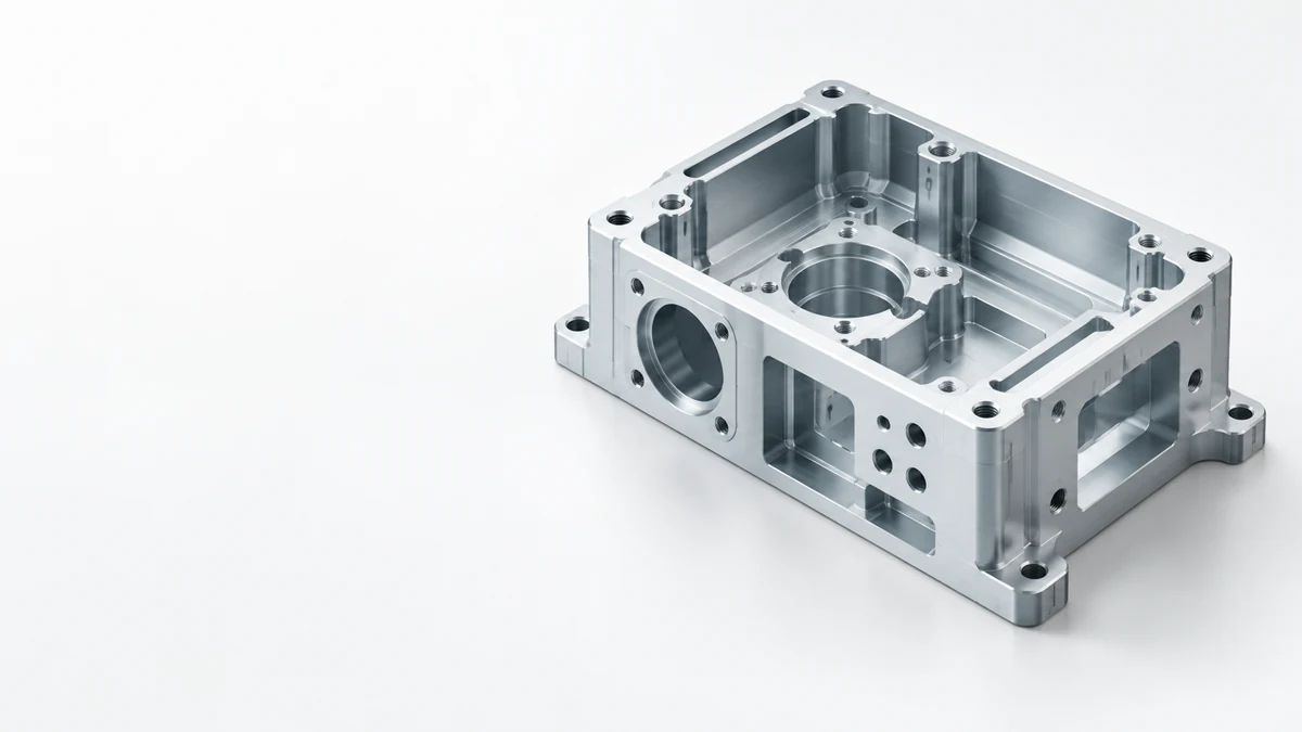
China CNC Milling Service
Send your drawing and get a milling review of the geometry, material, quantity, critical dimensions and finish before you commit to a price. We look at the cavities, slots, hole patterns and mounting faces on your actual design.
- Mark the faces and features that must fit or align.
- State the material grade and the quantity you need.
- Flag any feature that cannot change during the review.
- In-house production
- ISO 9001
- 24h quote response
- 80+ countries
What to check before a milling quote
Jump to the part, production or inspection question you need to settle first.
Milling Parts
Part families milling handles well
Feature Access
Pockets, slots, holes and side features
Design Tradeoffs
What to keep, what to relax
Setup and Datums
Datums that survive repositioning
Materials and Finishes
Grade, condition and finish inputs
Milling Production
Milled, held and checked in-house
Inspection Plan
What is checked, and against what
Quote Inputs
What to send for a firm quote
Milling FAQ
Ten questions buyers ask first
Request a Quote
Send your drawing to Parker
CNC milling parts
Part shape tells you more than a material label. Compare your drawing with these part families by the faces, pockets, slots, hole patterns and interfaces they share.
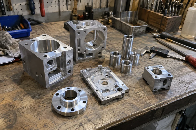
Housings and enclosures
A deep cavity, thin walls and mounting holes in one part. Mark the surfaces that locate internal components and the edges that must stay reachable for machining and inspection.
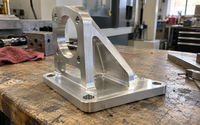
Brackets and mounting plates
Simple in outline, but the hole pattern controls the assembly. Mark the datum face, the mating surfaces and any holes that must line up with another part.
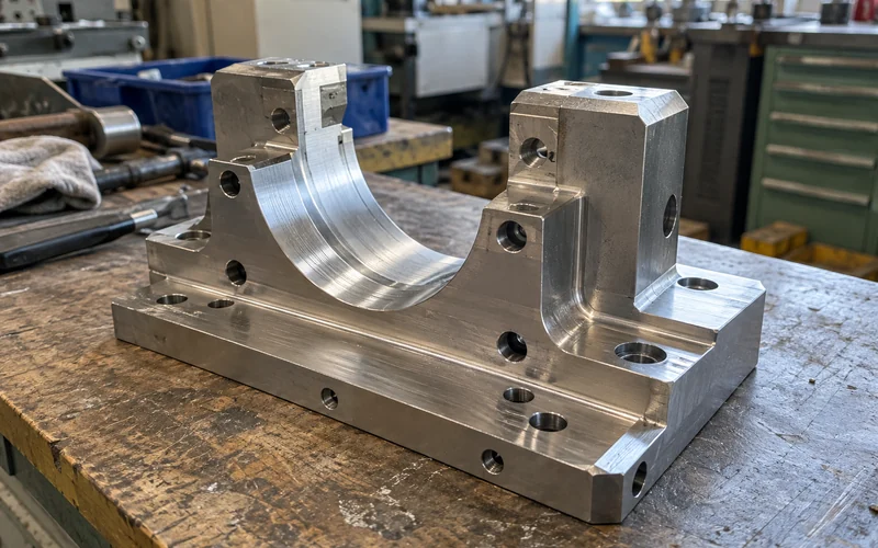
Fixtures and machine components
Slots, stepped faces and threaded holes work together. Show which surfaces clamp, locate or carry load so they are reviewed as one set.
If most of your features are round, such as diameters, shoulders and threads, start with CNC turning. To compare machining routes in general, see CNC machining.
Quote response within 24 hours for complete drawings.
Feature access
A pocket that looks simple in CAD can be hard to reach with a stable tool. Check the opening, depth and surrounding walls before you treat a feature as routine milling.
A 3D model shows the geometry. A 2D drawing shows which dimensions, surfaces and relationships must be kept. Send both when you have them, and mark any feature that cannot change.
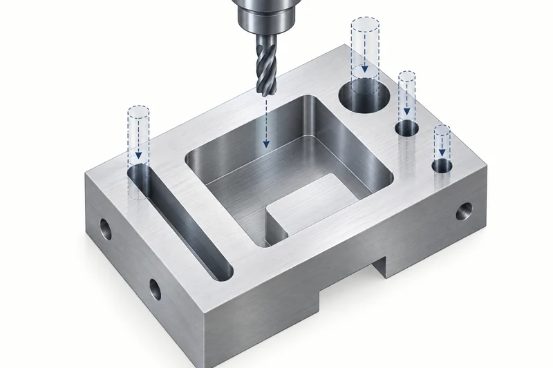
| Feature | Why access matters | What to show on the drawing |
|---|---|---|
| Pocket or cavity | Opening, depth and internal corners decide tool choice and reach. | Opening size, depth, corner intent and functional surfaces. |
| Slot | A narrow or deep slot limits tool access and chip removal. | Width, depth, end condition and any mating part. |
| Hole pattern | Direction, depth and link to datums shape the setup and inspection plan. | Hole sizes, positions, thread details and primary datums. |
| Side feature | A second access direction may need another setup or a different route. | Required side faces and their positional relationships. |
| Tall adjacent wall | A wall can block access to a nearby floor, edge or hole. | Wall height, access opening and critical surfaces. |
Why access matters Opening, depth and internal corners decide tool choice and reach.
What to show on the drawing Opening size, depth, corner intent and functional surfaces.
Why access matters A narrow or deep slot limits tool access and chip removal.
What to show on the drawing Width, depth, end condition and any mating part.
Why access matters Direction, depth and link to datums shape the setup and inspection plan.
What to show on the drawing Hole sizes, positions, thread details and primary datums.
Why access matters A second access direction may need another setup or a different route.
What to show on the drawing Required side faces and their positional relationships.
Why access matters A wall can block access to a nearby floor, edge or hole.
What to show on the drawing Wall height, access opening and critical surfaces.
Not sure a feature can be reached? Send the model and ask for a feature-access review.
DFM tradeoffs that lower cost
A small change to a noncritical feature can open a simpler machining route. Separate the features you must keep from the details that are open to review.
These are review points, not size limits. The final route depends on your drawing, the material and the setup chosen for your part.
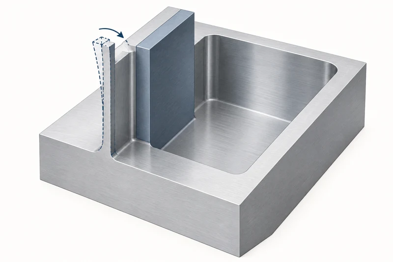
Thin walls
A wall can move during clamping or cutting and relax after material is removed. State its material, height, thickness and required final position.
Deep or narrow cavities
Tool reach and chip clearance get harder as a cavity deepens or its opening narrows. Name the floor finish, corner requirement and surfaces that must stay accessible.
Sharp internal corners
A rotating cutter always leaves an internal radius. If an insert has to fit the pocket, show the mating geometry and whether a relief is allowed.
Small holes and threads
Hole depth, entry direction and nearby surfaces decide tool selection and inspection. Give the thread standard, engagement length and any critical hole position.
Deburring and edges
A burr on a mounting face, slot or hole can stop an assembly. Mark edges that need a defined break and faces where a visible mark is not acceptable.
Setup and datums
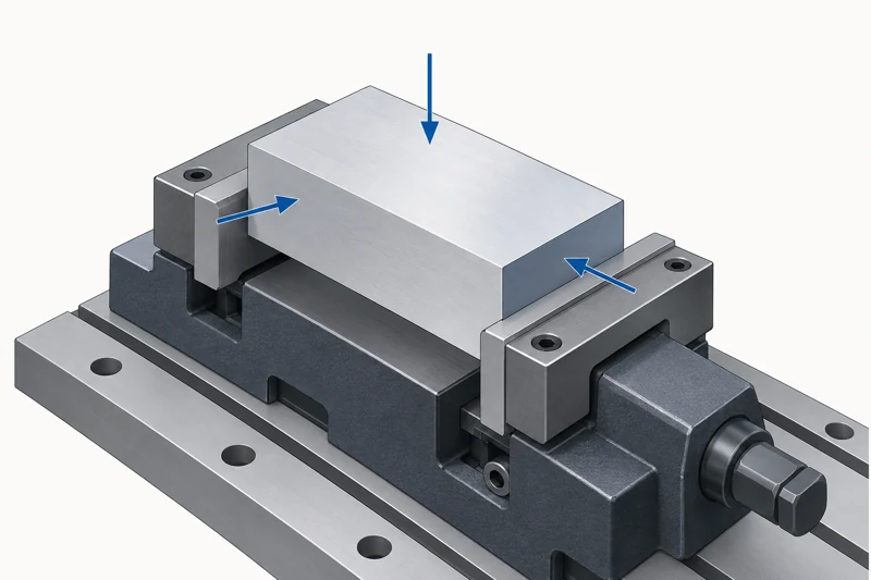
Milling a part from more than one side changes how each feature is located and checked. Show the primary datum, the faces free for clamping and the relationships that matter in assembly.
When a part is turned over for a second setup, the features cut in the first setup become the reference for the rest. Marking which relationships must survive that move is what keeps a two-sided part in tolerance.
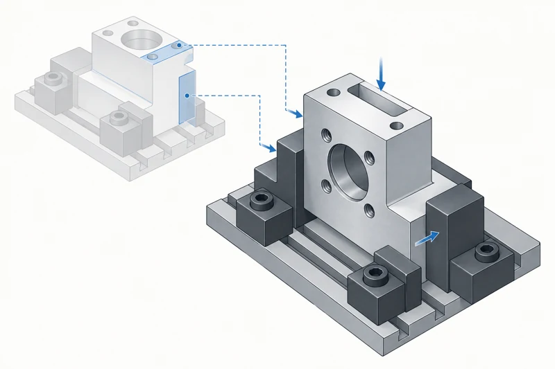
| Review point | Single-access part | Part needing another access direction |
|---|---|---|
| Feature direction | Key features are reachable from one main direction. | Side or underside features need another access direction. |
| Location | Features reference the same initial setup. | A later setup must hold the specified datum relationship. |
| Drawing input | Mark functional faces and hole locations. | Also mark the relationships that must survive repositioning. |
Single-access part Key features are reachable from one main direction.
Part needing another access direction Side or underside features need another access direction.
Single-access part Features reference the same initial setup.
Part needing another access direction A later setup must hold the specified datum relationship.
Single-access part Mark functional faces and hole locations.
Part needing another access direction Also mark the relationships that must survive repositioning.
A process label alone cannot pick the route. Some geometries justify a multi-axis review, which is a separate decision covered under 5-axis CNC machining.
No need to pick a machine before you ask
Mark the critical faces, datums and features, then send the drawing. The review weighs conventional milling, an extra setup or a multi-axis route for your part, and the next step is settling the material and finish.
Materials and finishes
Grade, condition and surface finish change how a part is machined and measured. State your requirement even if you would accept an alternative.
What to state about the material
- Grade: the specified alloy or polymer, or the performance requirement if the grade is open.
- Condition: temper, hardness or other condition when it affects fit or function.
- Substitution: whether an alternative grade may be discussed before quoting.
What to state about the finish
- Functional surfaces: faces, holes or threads where a coating or texture could change the fit.
- Appearance: the visible faces and the finish standard you expect.
- Masking: areas that must stay untreated.
- Final dimensions: which dimensions apply after finishing.
If your drawing calls for anodizing, plating, coating or passivation, name the process and the surfaces it applies to. Finishing runs in our own factory as well, and the finishing route is confirmed for each project. For how a finish affects fit and appearance, see surface finishing.
CNC milling production
We mill, finish and inspect your part in our own factory, so one team owns the result from drawing to shipment. Your quote names the route, from the setup and workholding to the final check.
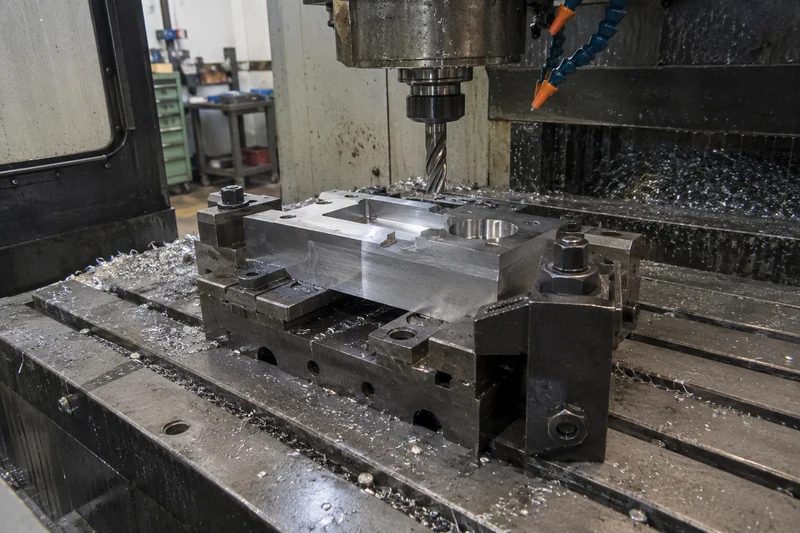
Machine setup
Your part is milled on our own machines, and the quote review shows which setup reaches each critical feature.
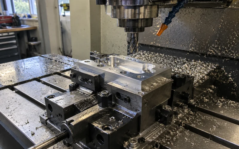
Workholding
Ask how the part is clamped and located, especially for thin walls and features on more than one side.
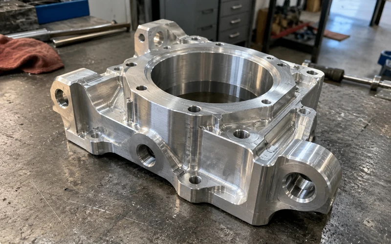
Finished part
Approve a sample of the finished part against your drawing before volume production starts.
Sample sign-off before production.
Tolerance and inspection
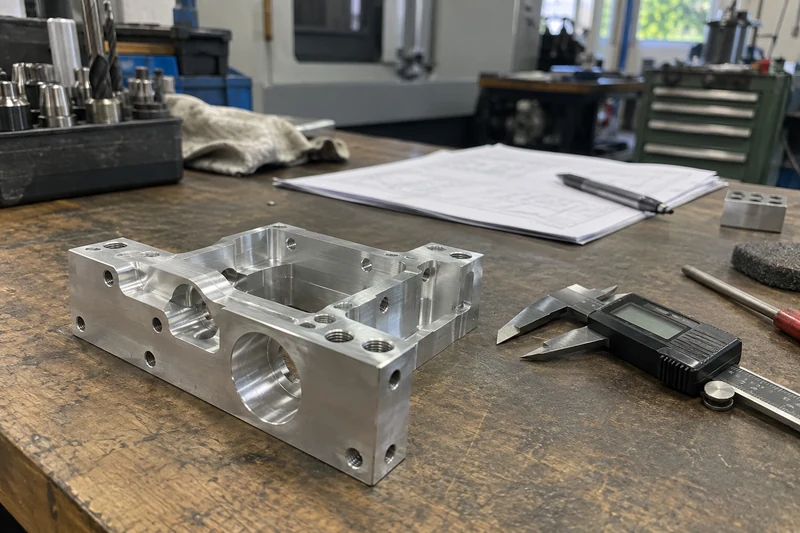
Inspection planning starts when the drawing shows what must fit, align or look right. Identify the datum scheme and the features that need more than a general dimensional check.
List any report or material document you need in the RFQ, and say whether a dimension applies before or after finishing. The inspection record is agreed for each order, so the checks match the features that matter to your assembly.
| Requirement | Define on the drawing | Verification to agree |
|---|---|---|
| Mounting face | Datum, flatness or relationship to another face. | How the face is located and measured. |
| Hole pattern | Hole size, position and link to the datum system. | Measurement method and features in the record. |
| Mating feature | Fit, clearance and critical dimensions. | Part condition and measuring setup. |
| Visible surface | Finish area and appearance criteria. | The reference or acceptance method. |
| Finished dimension | Whether it applies before or after surface treatment. | The stage at which it is checked. |
Define on the drawing Datum, flatness or relationship to another face.
Verification to agree How the face is located and measured.
Define on the drawing Hole size, position and link to the datum system.
Verification to agree Measurement method and features in the record.
Define on the drawing Fit, clearance and critical dimensions.
Verification to agree Part condition and measuring setup.
Define on the drawing Finish area and appearance criteria.
Verification to agree The reference or acceptance method.
Define on the drawing Whether it applies before or after surface treatment.
Verification to agree The stage at which it is checked.
For tight geometric tolerances and batch-to-batch consistency, see precision machining.
Missing a file? Start the review anyway
Begin with the model and the features that matter. Open points such as finish, final quantity or inspection records can be settled during the review, and the checklist below shows what makes a first quote firm.
Quote inputs
A complete request lets the milling route be assessed and questions raised before pricing. Send what you have and mark what is still open.
Include in the first request
- 3D model or usable CAD geometry, plus a 2D drawing for critical dimensions and GD&T.
- Material grade, or the performance requirement if the grade is open.
- Quantity for the first order and any expected repeat quantity.
- Finish, visible surfaces and important edge requirements.
- Critical features, datums and inspection requirements.
- Project timing and destination when they affect the quote.
Helpful context
- Features that may change after a manufacturing review.
- Mating parts or assembly conditions behind a critical fit.
- Whether this is a prototype, a revision or a repeat order.
Quote response within 24 hours for complete drawings.
CNC milling FAQ
Short answers to the questions that usually come up before a milling quote.
Is CNC milling suitable for my part?
Milling is the route to review when your drawing has accessible flats, pockets, slots or hole patterns. Material, feature access and the required datum relationships decide whether it fits your part.
What files should I send for a milling quote?
A 3D model and a 2D drawing when available, plus the material, quantity, finish, critical dimensions and any features that cannot change.
Can deep pockets be CNC milled?
A deep pocket needs a review of opening size, depth, internal corners, tool access and material. Share the model and mark the pocket surfaces that affect fit or function before assuming a depth limit.
How are sharp internal corners handled?
A rotating cutter always leaves an internal radius. If the corner must take a mating part, show that part or say whether a relief or design change is allowed.
Can thin walls be CNC milled?
Thin walls need a review of material, wall height, clamping and the final dimensional requirement. With the drawing, the route and the inspection method are assessed together.
When should a multi-axis route be reviewed?
When key features face different directions or repositioning would break a critical relationship. See 5-axis CNC machining for how that route is assessed.
How is CNC milling different from turning?
Milling suits non-round faces, pockets and slots. Parts defined mainly by diameters and concentric features usually start with CNC turning.
How should I specify critical tolerances?
Identify the dimensions and datum relationships that control assembly or function, and put the tolerances on the drawing. Achievability and verification are reviewed for your material and geometry.
Can surface finishing affect final dimensions?
Yes. A coating or treatment can change a fit or contact surface. Name the finish, the masked areas and the dimensions that apply after finishing.
What should stay controlled for repeat orders?
The approved drawing revision, material, critical features, finish and inspection criteria. If the part or its use changes, send the revision before the next quote or run.
Request a CNC milling quote
Send the drawing and tell us which features matter. Parker reviews it and replies with questions or a quote.

Parker
Your CNC Milling Contact, HONGYI
I'm Parker. Send your drawing or CAD model and tell me which features must fit, align or meet an appearance requirement. Add the material, quantity and finish if you know them.
On a 2D drawing, mark the critical dimensions and datums, plus any inspection requirement and timing. If some details are still open, tell me what you need help deciding.
- Reply within 24 hours
- In-house production
- Drawings kept confidential