
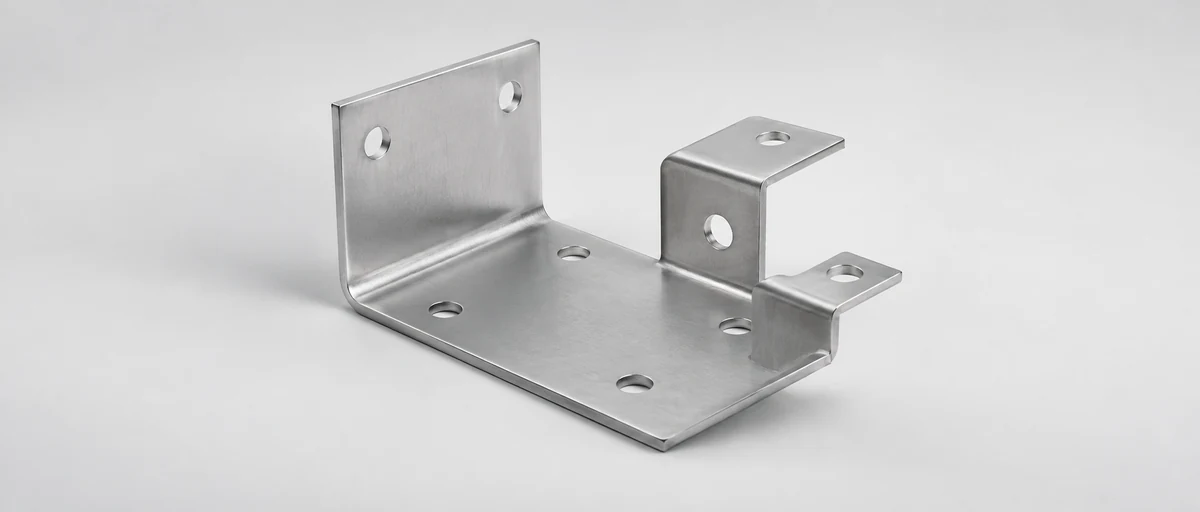
China Metal Bending Service
A bent part is accepted in its formed condition. The flat pattern is an input; your decision rests on finished angles, radii, mating dimensions and surface condition.
- Send the finished drawing with the material grade and thickness.
- Mark the inside radius, bend direction and critical formed dimensions.
- Flag protected visible faces, and link any flat pattern to its revision.
- In-house production
- ISO 9001
- 24h quote response
- 80+ countries
What to settle before bending
Jump to the geometry, material or inspection question you need to settle first.
Bent Parts
The formed shape you accept
Materials and Thickness
Grade, temper and rolling direction
Bend Geometry
Sequence, access and the envelope
Radius and Tooling
Inside radius, tool marks and access
Hole Edge Distance
Holes and slots near the bend
Springback Control
The finished angle and how it is measured
Surface Protection
Visible faces and tool marks
Bending Production
Blank, setup and repeat orders
Inspection Plan
Angles, envelope and fit checks
Quote Inputs
What to send for a firm quote
Bending FAQ
Ten questions buyers ask first
Request a Quote
Send your drawing to Parker
Bent parts, defined by the formed shape
Show the delivered shape, not only the fold lines. Mark flanges, mounting holes, mating faces and the surfaces that must stay unmarked.
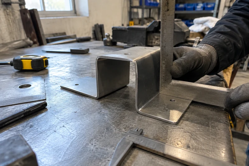
Flanges and mounting holes
Show each flange and the holes that must line up after forming, measured from a stated datum.
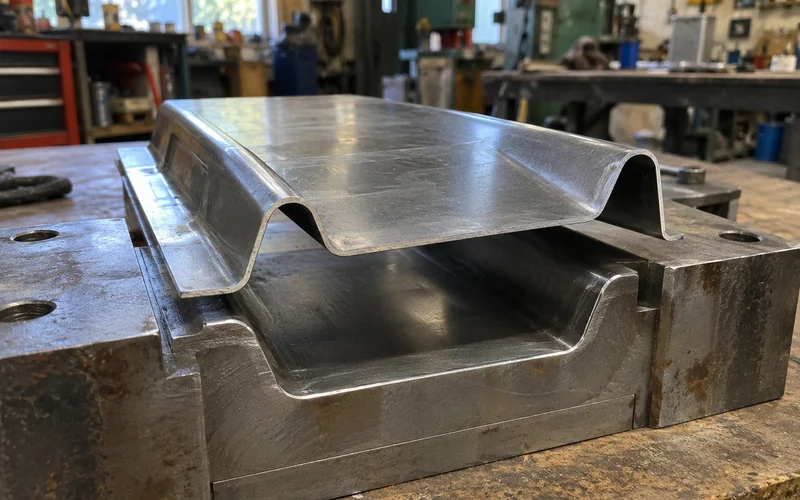
Mating faces
Mark the faces that meet another part. They set the formed dimensions you will inspect.
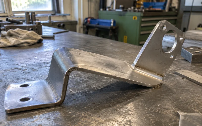
Later operations
If the part later receives hardware, welding or coating, state the condition in which the bend dimensions are accepted.
This page covers bend feasibility and the formed result. A full cut, bend, weld and finish purchase belongs with sheet metal fabrication. A stable, high-volume press-formed part may belong with metal stamping.
Quote response within 24 hours for complete drawings.
Material condition and thickness
Bend behavior changes with material state, rolling direction and thickness variation. Name the grade, temper and nominal thickness, and agree substitutions before quoting.
| Input | What to state | Why it matters |
|---|---|---|
| Grade and temper | The grade and its temper or condition. | Material state changes bend behavior. |
| Thickness | The nominal thickness. | Variation changes angle, radius and flange length. |
| Rolling direction | Any direction requirement for the blank. | Bend behavior changes with it. |
| Film or directional finish | Which face must be outward after forming. | Keeps the finish on the visible side. |
| Substitution | Whether another grade is allowed. | It can alter springback, minimum radius and marking. |
| Supplied blanks | Incoming condition, and who bears trial or setup loss. | Settles scrap responsibility before the first run. |
What to state The grade and its temper or condition.
Why it matters Material state changes bend behavior.
What to state The nominal thickness.
Why it matters Variation changes angle, radius and flange length.
What to state Any direction requirement for the blank.
Why it matters Bend behavior changes with it.
What to state Which face must be outward after forming.
Why it matters Keeps the finish on the visible side.
What to state Whether another grade is allowed.
Why it matters It can alter springback, minimum radius and marking.
What to state Incoming condition, and who bears trial or setup loss.
Why it matters Settles scrap responsibility before the first run.
Considering a substitute grade? Ask before you approve it.
Bend geometry and sequence
The bend sequence can decide whether the final shape is possible at all. Identify inside and outside faces, bend directions and sequence constraints in the model or drawing.
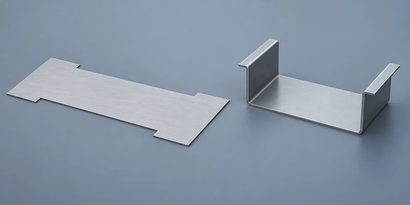
Short flanges
A short flange can block tool access. Show its length and whether it can change.
Return bends and close walls
An earlier bend can block the tool for a later one. Mark the sequence constraints.
Functional envelope
Dimension the envelope from consistent datums so every formed feature is measured the same way.
Mating interface
If an assembly interface is critical, show the mating part or the fixture it fits.
Flat length
A flat length calculated before the tooling and material are fixed is a development input, not proof of final fit.
Inside radius and tooling
The inside radius affects cracking risk, outside appearance and developed length. Specify it where fit or strength depends on it; otherwise approve a proposed radius before production files are final.
Your quote states the radius and tooling assumptions behind the price, so you can approve them before production.
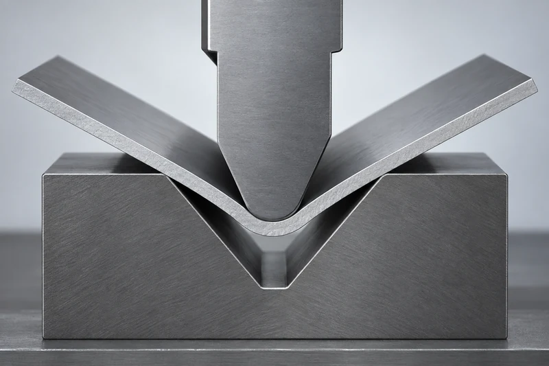
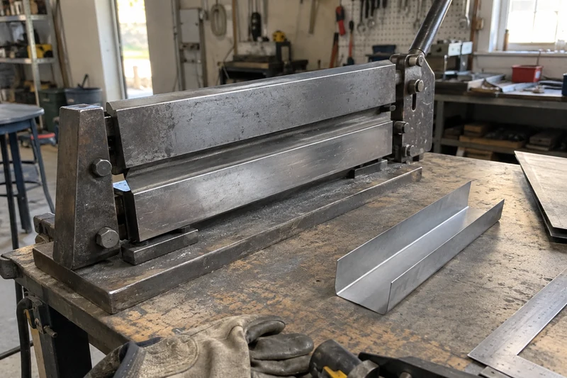
Specified radius
If a radius controls fit, strength or appearance, put it on the drawing.
Proposed radius
If the radius is open, allow a tooling review and approve the proposed radius as a drawing revision.
Tool contact
Tooling can mark the outside face, and tool access may dictate bend order. Mark the faces that must stay clean.
Holes and slots near a bend
A hole or slot close to a bend can stretch, distort or move relative to the final datum. Mark the critical openings and their required position after bending.
Separate the dimensions controlled on the blank from those controlled after forming. A first-article measurement then shows whether the bend sequence keeps functional holes aligned.
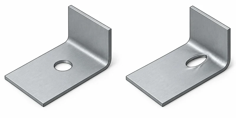
Mark on the drawing
- Critical holes and slots, with their required position after bending.
- Dimensions controlled on the flat blank.
- Dimensions controlled after forming.
Options the review may propose
- Relief geometry near the bend.
- A secondary drilling operation after forming.
- A changed bend sequence.
- A first-article check of hole alignment in the formed state.
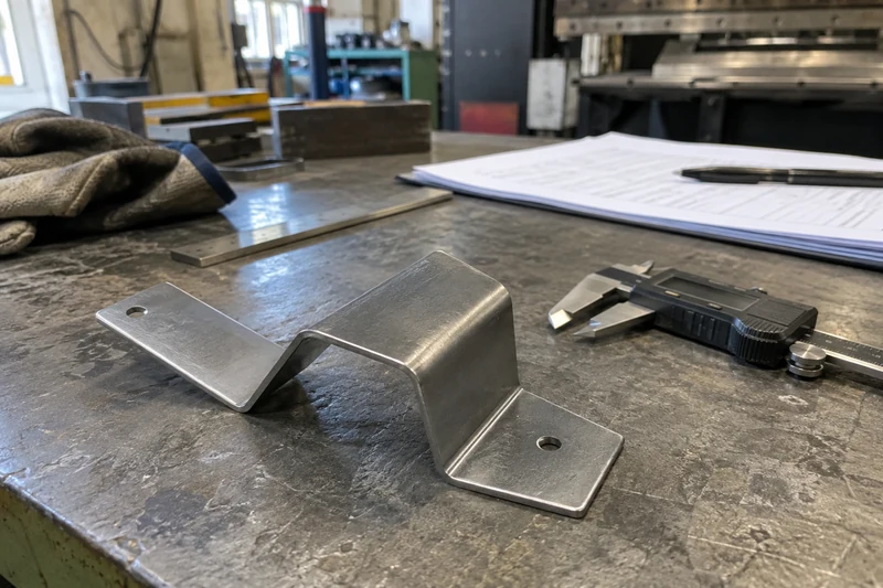
Springback and the finished angle
Once the forming load is removed, the material recovers some angle. The nominal angle on your drawing is an acceptance requirement, not a setup instruction.
The result depends on the actual material, thickness, grain direction, radius and tooling, so the angle is agreed and proven before production.
Set the tolerance
Agree the finished-angle tolerance and how it will be measured.
Fix the material
Confirm grade, temper and thickness, since springback depends on them.
Run trial parts
Trial parts may be used to adjust the forming program or the tool choice.
Record and sign off
Record the results against the material lot and drawing revision, then sign off the sample before production.
Sample sign-off before production.
Protecting visible faces
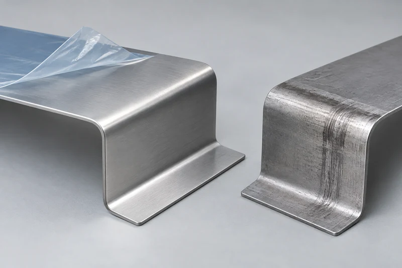
Identify visible faces before tooling is selected. Film, pads, tooling choice and handling can reduce marking, but each needs review for your material and finish.
For a brushed or coated surface, approve a physical sample and its viewing condition. Subtle tool marks are hard to judge from photographs alone.
| Item | What to define |
|---|---|
| Visible faces | Which faces are visible after forming. |
| Witness marks | The marks you accept, and where. |
| Post-form work | Whether polishing or coating is permitted. |
| Appearance reference | A physical sample and viewing condition. |
| Packaging | The packaging that keeps the delivered appearance. |
What to define Which faces are visible after forming.
What to define The marks you accept, and where.
What to define Whether polishing or coating is permitted.
What to define A physical sample and viewing condition.
What to define The packaging that keeps the delivered appearance.
Brushed or coated face? Mark it on the drawing and ask for a sample.
Prove the bend on a first part
Radius, sequence, hole positions and visible faces are now on the drawing. Next, prove them on a first part in the agreed material, then hold that result through production and inspection.
Bending production and repeat orders
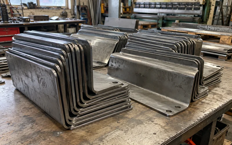
Production should control the correct blank, orientation, setup, first-off inspection and part identification. We bend every part in our own factory, so that control stays with one team from blank to finished shape.
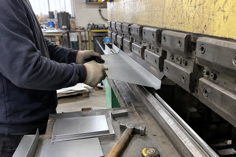
Blank and setup
Ask how the correct blank and orientation are confirmed at setup.
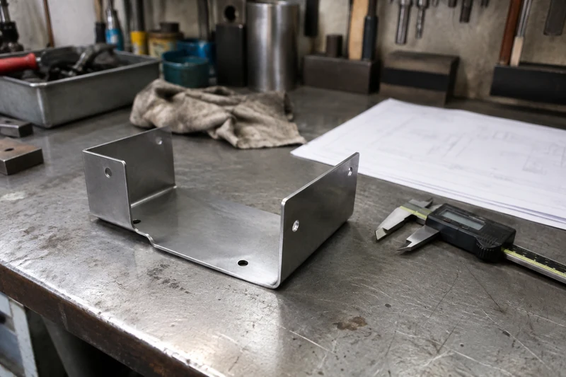
First-off part
Approve the first formed part against your drawing before the lot runs.
Repeat orders
Ask that any change in material lot, sheet condition or tooling is reviewed against the approved formed part.
Sample sign-off before production.
Inspecting the formed part
Inspect finished angles, radii where specified, the overall envelope, mating dimensions, hole locations and surface condition.
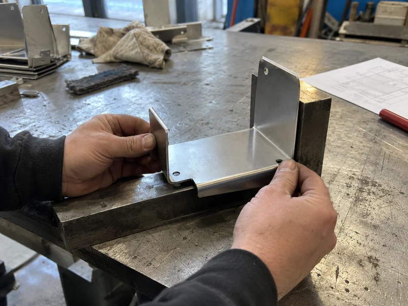
Angles and radii
Measure the finished angles, and the radii where the drawing specifies them.
Envelope and mating dimensions
Check the overall envelope and the dimensions that meet other parts.
Hole locations
Confirm hole positions in the formed state.
Surface condition
Check visible faces against the agreed sample or standard.
Fixture or direct
The drawing says which features use a fixture and which are measured directly. A fit check can complement readings when the part goes into an assembly.
Records
Agree first-article and repeat-lot records, drawing revision, material lot and sample frequency. The record is set for each order.
Quote inputs for a bending RFQ
Send the finished-state package, and ask the quote to spell out its assumptions so you can compare offers on the same basis.
Include in the RFQ
- Finished-state 3D model and 2D drawing, plus the flat pattern if controlled.
- Material grade, thickness and quantity.
- Bend radii and angles.
- Critical mating dimensions and visible surfaces.
- Downstream operations, and which dimensions are accepted after coating or assembly.
Ask the quote to state
- Material responsibility.
- Tooling assumptions.
- Sample approval.
- Allowed surface marks.
- Inspection deliverables.
If a radius or relief change is proposed, approve it as a drawing revision before production.
Quote response within 24 hours for complete drawings.
Metal bending FAQ
Short answers to the questions that usually come up before a bending quote.
Is the finished angle or the flat length the acceptance basis?
The released finished-state drawing defines acceptance. A flat length can guide blank preparation, but approve it with the material and tooling route that produces the formed part.
What if a hole is close to the bend line?
Review its size, distance, orientation and required final position. A relief, a changed sequence or a secondary operation may be needed; check the first article in its formed state.
Can springback be promised before the material condition is fixed?
A finished-angle target can be set, but the setup and likely correction depend on grade, temper, thickness and tooling. Confirm the material and validate with representative samples.
Must the inside radius be specified?
Specify it if it controls fit, strength or appearance. Otherwise ask for a reviewed radius proposal and approve the resulting design before production.
How are tool marks on a visible face limited?
Mark the visible face, define an approved sample or written standard, and agree tooling protection and inspection conditions. Include packaging if transit marks are a risk.
Can multiple bends affect features formed earlier?
Yes. Later tool contact and the bend sequence can distort or block earlier flanges. Review access and check the final datums on a first article.
When does a formed part belong with Metal Stamping?
When a dedicated press tool and repeat production are the main procurement route. Compare the tooling investment with expected volume and drawing stability.
Who corrects shape after the part is welded?
We do when welding is part of your order, since cutting, bending, welding and any correction run in our own factory. Define the delivered condition and the post-weld dimensions you accept. For the weld itself, see metal welding; a cut, bend and weld deliverable is a broader fabrication scope that needs a final inspection plan.
How does thickness variation affect the first setup?
It can change bend angle, radius and flange length. Check the actual material against the approved range and measure a representative first part before releasing the lot.
How are critical dimensions measured in assembly position?
Define datums and an assembly or functional fixture if direct measurement is ambiguous. Agree the method with the drawing so the result can be repeated.
Request a metal bending quote
Send the finished drawing and tell us which dimensions matter. Parker reviews it and replies with questions or a quote.

Parker
Your Metal Bending Contact, HONGYI
I'm Parker. Send me the finished drawing with the material and thickness, bend radii and angles, critical assembled dimensions, quantity and visible-surface requirements.
Include a flat pattern if you have one, and tell me about any cutting, welding or finish operations the part needs before delivery.
- Reply within 24 hours
- In-house production
- Drawings kept confidential