

Choosing between CNC milling and CNC turning is not about declaring one process better. It is about matching the process to the part geometry, material grade, tolerance plan, surface finish, setup risk, inspection method, and production intent.
For custom parts, a vague process label can create avoidable quote gaps. A round shaft with threads is not reviewed like a pocketed housing. A mostly round component with cross-holes may need a hybrid route. A sheet metal bracket or molded plastic cover belongs in a different process discussion altogether.
Use the sections below as a specification review before sending an RFQ. The goal is to help a supplier choose milling, turning, or turn-mill machining from evidence in the model and drawing.
Should the part geometry point to CNC milling or CNC turning?
Choose CNC turning when the part is mainly rotational, such as a shaft, bushing, disk, cone, flange, or threaded round component. Choose CNC milling when the part is mainly prismatic, pocketed, slotted, flat-sided, multi-face, or irregular in shape.
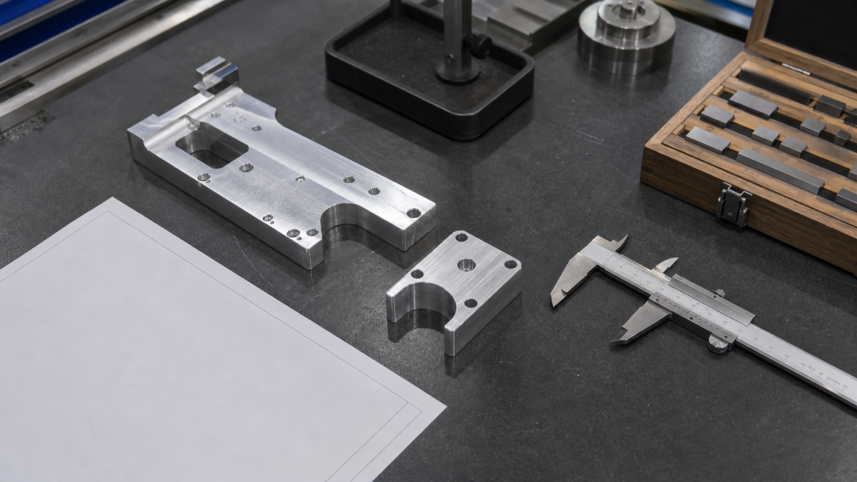
Start with the shape before you start with the machine name. In turning, the workpiece rotates while a cutting tool forms outside diameters, inside diameters, faces, grooves, bores, and threads. That makes turning a natural fit when the part is organized around a central axis.
In milling, the cutter rotates and moves across a workpiece that is held, indexed, or repositioned. That makes milling more suitable for blocks, plates, housings, brackets, pockets, slots, pads, bosses, gasket faces, and irregular surfaces where tool access from different directions matters.
| Geometry signal | More likely process | Specification consequence |
|---|---|---|
| Shaft, sleeve, bushing, spacer | CNC turning | Diameters, bores, grooves, and faces are controlled around one axis |
| Rectangular plate, housing, bracket | CNC milling | Pockets, hole patterns, and flat faces drive cutter access and setup plan |
| Flange with bolt circle and turned diameter | Turning or turn-mill | Round features dominate, but off-axis holes may control setup choice |
| Complex contour or angled face | CNC milling | Toolpath access and surface relationship become the main review items |
Example: A cylindrical spacer with an outside diameter, inside bore, and chamfers should normally be reviewed as a turning part. A rectangular aluminum cover with pockets, mounting holes, and a gasket face should normally be reviewed as a milling part.
The RFQ should describe the dominant geometry1 in plain terms. If the model contains both round and prismatic features, say which features control fit, sealing, alignment, or appearance. That helps the supplier judge whether one process is enough or whether a hybrid plan is more realistic.
When does a round part need turn-mill machining instead of separate operations?
A round part may need turn-mill machining when it combines cylindrical features with cross-holes, wrench flats, pockets, slots, or other off-axis details. The decision depends on whether those features must stay aligned to the turned diameter or can be handled as secondary operations.
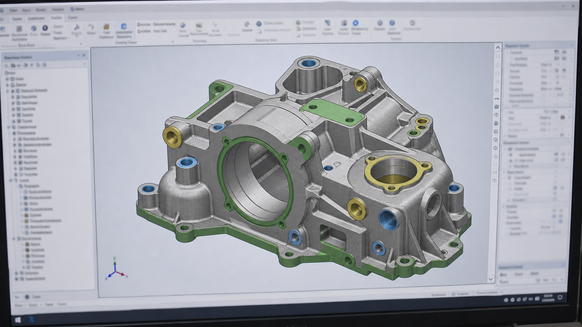
Turn-mill machining becomes relevant when a part starts as a lathe candidate but cannot be completed cleanly with turning alone. A plain shaft, sleeve, or bushing may only need turning. A shaft with a radial hole, wrench flat, off-center pocket, or milled slot may need either secondary milling or a combined route.
The practical question is not only whether the extra feature can be cut. The question is whether its location matters relative to the turned diameter, bore, face, or thread. If a cross-hole must align closely to a bore, reclamping after turning can introduce tolerance stack-up between setups. A combined process may reduce that risk when the geometry and supplier capability support it.
Scenario: A round valve-style component has an outside diameter, an internal bore, two flats for assembly, and radial holes that must align with the bore. If the RFQ only says “CNC turning,” the supplier may quote turning plus a separate milling operation. If the drawing identifies the bore-to-hole relationship as critical, the supplier can evaluate whether a turn-mill setup2 is a better route.
Useful RFQ notes include:
- Which turned diameters, bores, or faces are functional datums
- Which off-axis features must align to those turned features
- Whether flats, holes, and pockets are functional or only for clearance
- Whether secondary operations are acceptable
- What inspection evidence is expected for feature relationships
Turn-mill is not automatically the premium answer. It is worth considering when it reduces reclamping, protects alignment, or simplifies inspection for features that affect assembly or performance.
How much milling axis capability does the part actually need?
The part does not need advanced milling axis capability unless the geometry requires it. Simple 2.5D pockets, holes, slots, and flat faces may fit 3-axis milling, while undercuts, compound angles, and complex free-form surfaces may justify more complex milling access.
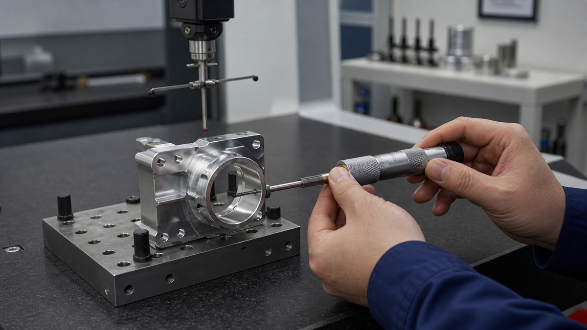
Specifying “5-axis CNC machining” can sound precise, but it may also narrow the supplier pool or change quoting assumptions when the part does not need that capability. Axis count should follow tool access3, not appearance. If the critical features can be reached from the top and a few indexed sides, a simpler milling route may be enough.
What makes axis access difficult?
Axis access becomes difficult when a cutter cannot reach the feature without colliding with a wall, rib, fixture, or neighboring surface. Deep pockets, undercuts, tall ribs, angled holes, sculpted surfaces, and features on several sides can all change the machining plan.
A focused access review should ask:
- Are most features simple 2.5D pockets, holes, slots, and flat faces?
- Can critical surfaces be reached from one side or a small number of orientations?
- Does any undercut require the tool to approach from a non-standard direction?
- Are compound angles or free-form surfaces functional, cosmetic, or only clearance?
- Does inspection need to verify relationships across several machined sides?
Common specification mistake: Requiring advanced axis machining because the model looks complex, while the critical features are shallow pockets, standard holes, and flat faces. The supplier may still choose a more capable machine for their own efficiency, but the buyer does not need to require it unless the geometry demands it.
The drawing should identify functional faces, tool-access limitations, and feature relationships. With that information, the supplier can decide whether 3-axis milling, indexed machining, or more complex simultaneous motion is appropriate.
Is the project CNC machining, sheet metal fabrication, stamping, or molding?
CNC milling and CNC turning are machining processes that remove material from solid stock. They should not be confused with CNC turret punching, sheet metal fabrication, metal stamping, or plastic injection molding, because each process uses different material forms, tooling, geometry rules, and cost drivers.

Process language matters before quoting. A machined housing, a punched sheet metal bracket, a stamped clip, and an injection molded plastic cover may all be custom parts, but they are not interchangeable manufacturing routes. Each process starts with a different material form and creates different specification risks.
| Process term | Typical starting material | Main specification concerns |
|---|---|---|
| CNC milling | Solid block, plate, billet, casting, or extrusion | Pockets, faces, hole patterns, surface finish, datum relationships |
| CNC turning | Bar, tube, round blank, or near-round stock | Diameters, bores, shoulders, grooves, threads, concentric features |
| CNC turret punching or CNC punch press | Sheet metal | Hole patterns, formed features, sheet thickness, burr direction |
| Metal stamping | Sheet or coil | Dedicated tooling, springback, burr direction, forming risk, production volume |
| Sheet metal fabrication | Sheet metal | Flat pattern, bend radius, bend sequence, welds, finish, assembly fit |
| Plastic injection molding | Resin pellets formed in a mold | Draft, wall thickness, gate location, shrinkage, material grade |
“CNC turret punching, CNC punch press, CNC-controlled stamping equipment, or metal stamping depending on the actual process” is not a precise standard process term by itself. It may refer to CNC turret punching, a CNC punch press, CNC-controlled stamping equipment, or general metal stamping. The RFQ should clarify the intended process, material form, and production intent.
If the part is machined from solid stock, use CNC milling, CNC turning, drilling, boring, reaming, or turn-mill language. If it begins as sheet metal, specify turret punching, laser cutting, bending, welding, or stamping as appropriate. If it is a mold-based plastic part, treat draft, wall thickness, gate location, and shrinkage as molding issues rather than machining issues.
Which tolerances and surface finish requirements truly control the part function?
Specify tight tolerances and surface finish only where they affect fit, sealing, alignment, motion, or performance. Blanket precision requirements can increase machining and inspection effort without improving the part, especially when non-critical pockets, edges, and cosmetic surfaces do not need the same control.
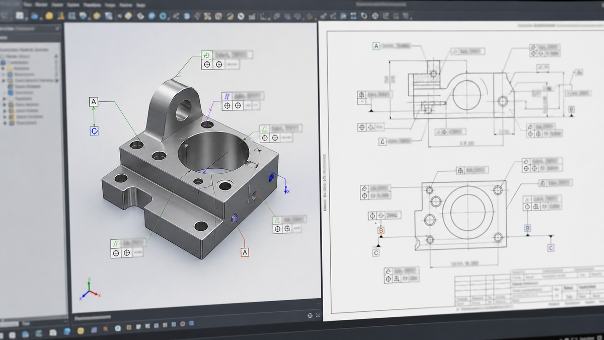
Tolerance and surface finish are instructions for manufacturing and inspection. A bearing bore, sealing face, dowel hole, or mating shoulder carries a different risk than a lightening pocket or cosmetic edge. When every dimension is marked as critical, the supplier has less room to choose an efficient process plan.
For many non-critical aluminum CNC machined features, a general tolerance4 around ±0.10 mm to ±0.13 mm can be a practical quoting baseline when tighter control is not required. Treat that as supplier- and geometry-dependent, not a universal capability claim. General tolerances normally belong in the drawing notes or title block, or through an appropriate standard such as ISO 2768 where applicable.
A useful tolerance plan separates:
- Functional features: bores, shafts, sealing faces, press-fit areas, dowel holes, bearing seats
- Assembly features: mounting holes, mating faces, alignment pads, clearance slots
- Non-critical features: relief pockets, cosmetic edges, lightening cuts, non-contact surfaces
- Finish-sensitive areas: sliding surfaces, sealing surfaces, visible faces, coated areas
- Inspection scope: hand tools, in-process checks, final dimensional reports, or CMM verification when needed
Example: A milled housing may need a controlled flat sealing face and accurate dowel-hole position, while internal weight-reduction pockets can stay under general tolerance. Treating every pocket wall as precision-critical can increase quote complexity without improving the assembled product.
Finish should be handled the same way. If anodizing, coating, or plating affects a critical fit, note whether finish buildup matters on bores, threads, sealing faces, or masked areas. Tight tolerances should be tied to function and a realistic inspection method.
How many setups will the chosen machining route require?
Setup count matters because each reclamp, index, or secondary operation can affect alignment, inspection effort, and cost. Features made in one setup are usually easier to control relative to each other than features machined from different sides or after repositioning.

A setup is the way the part is held and oriented while features are machined. A part can look simple but become difficult when critical features are split across multiple setups. Every flip, reclamp, or secondary operation can add variation between the machined features.
Scenario: A round component has a turned outside diameter, a bore, and a milled side port. If the side port is only for clearance, a secondary operation may be acceptable. If it must align tightly to the bore, the RFQ should flag that relationship before quoting. The supplier can then review fixturing, turn-mill machining, datum selection, and inspection sequence.
Setup-sensitive geometry5 includes:
- Deep pockets that require long tool reach
- Thin walls that can move during clamping or cutting
- Features on multiple sides of the part
- Broad plates where flatness or parallelism matters
- Long hole patterns across a large distance
- Face-to-bore, top-to-side, or hole-to-diameter relationships
- Threads or holes close to minimum wall sections
Which relationships should be called out?
The drawing should identify relationships that affect function. If a hole pattern must align to a mating face, use suitable dimensions, datums, or GD&T. If a pocket only removes weight, it may not need the same relationship control.
Setup count is also a quoting signal. More setups can mean more programming, workholding, tool changes, in-process checks, and final inspection. Multi-setup machining is common, but it should be quoted with the true alignment risk visible in the RFQ.
Could turning be more efficient when the part is mostly round?
Yes, turning may be the more efficient route when the part is mostly round and the required operations are facing, boring, drilling on center, grooving, threading, or parting. Milling should not be the default unless the geometry or off-axis features require it.
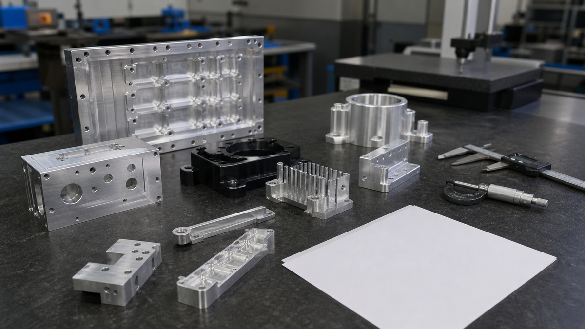
Turning is built around rotating stock6. When the finished part is organized around a central axis, turning usually matches the manufacturing problem directly. A lathe-style process can form outside diameters, inside diameters, shoulders, grooves, chamfers, faces, bores, and threads without treating a round part like a rectangular blank.
That does not make every round part easy. Material grade, slenderness, wall thickness, bore depth, surface finish, and tolerance relationships still matter. A long thin shaft may need support and careful workholding. A thin sleeve may distort if clamping pressure is not considered. A threaded feature needs a clear thread callout and acceptance requirement.
Common specification mistake: Sending a round spacer for quote as a “CNC milled part” because milling is being used as a generic synonym for machining. A good supplier may still identify the turning route, but the RFQ is clearer if it says the part appears suitable for CNC turning, with secondary milling only if required by the model.
When should milling still be considered?
Milling may be needed when the round part has flats, radial holes, slots, off-center pockets, non-round mounting features, or surfaces that cannot be produced by turning alone. The important distinction is whether those features are minor clearance details or whether they control the part’s function.
A mostly round part should be quoted with the model, drawing, material grade, critical diameters and bores, thread specifications, finish requirements, quantity, and inspection expectations. If off-axis details exist, identify which ones are functional and how they relate to the turned features.
What tool engagement risks should be flagged before quoting?
Flag slender sections, thin walls, deep pockets, unsupported features, and finish-critical surfaces before quoting. Turning uses continuous single-point cutting, while milling uses intermittent multi-point cutting, so the risk review should consider chatter, workholding, tool access, and inspection method.
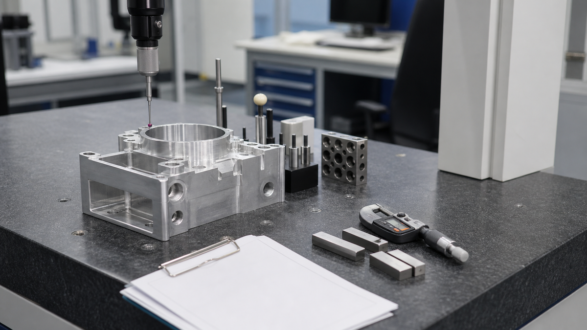
Tool engagement7 describes how the cutter contacts the material. In turning, a single-point cutting tool is typically engaged continuously as the workpiece rotates. In milling, a rotating multi-point cutter repeatedly enters and exits the cut. That difference can affect surface finish, vibration, burr formation, tool access, and workholding.
| Risk signal | Practical consequence | RFQ detail to provide |
|---|---|---|
| Long slender turned feature | May need support, controlled cutting forces, and defined runout expectations | Critical diameters, length, straightness, runout if applicable |
| Thin wall or thin floor | Can move during clamping or cutting, changing measured size after release | Wall thickness, functional surfaces, acceptable distortion if defined |
| Deep narrow pocket | Long tool reach can reduce rigidity and raise chatter risk | Pocket depth, corner radii, bottom finish, critical walls |
| Finish-critical face or bore | Process sequence and measurement method may change | Required finish, mating function, inspection expectation |
| Intersecting holes or slots | Burrs may affect fit, sealing, or assembly | Burr direction concerns, deburring requirements, edge break notes |
Chatter is a common failure mode to consider, especially with slender parts, thin walls, long tool reach, or intermittent cutting conditions. Do not treat chatter as a problem solved by choosing one process name. Identify the risk features early so the supplier can plan tool selection, workholding, cutting sequence, and inspection.
Example: A deep milled pocket with small inside corners may force long-reach tools. Increasing corner radii or separating functional walls from clearance walls can give the supplier more room to choose a stable toolpath.
Turning has its own engagement risks. Long unsupported shafts, thin rings, and deep bores should be flagged because they can affect stability, finish, and measurement repeatability.
What RFQ information helps a supplier choose the right machining process?
A useful RFQ gives the supplier enough evidence to choose milling, turning, turn-mill machining, or another process without guessing. Send the model, drawing, material grade, quantity, production intent, critical tolerances, finish, inspection needs, revision level, and delivery expectations.

The RFQ should do more than ask for a price. It should give the supplier enough context to choose the manufacturing route and quote the real work. Milling, turning, and turn-mill decisions depend on geometry, material, tolerance, finish, setup count, inspection method, and whether the job is a prototype, pilot run, or production release.
Use this RFQ and approval checklist8 before asking for a machining recommendation or quotation:
- 3D CAD model showing complete geometry
- Controlled 2D drawing with units, part number, revision level, and title block notes
- Material grade and condition, not just “aluminum,” “steel,” or “plastic”
- Quantity for the immediate order
- Prototype, pilot, or production intent
- Estimated annual usage or ramp-up plan if known
- Critical tolerances and the features they apply to
- GD&T requirements when position, flatness, perpendicularity, parallelism, coaxiality, or profile matters
- Surface finish requirements for sealing, sliding, visible, or functional surfaces
- Edge break, chamfer, deburring, or burr direction expectations where relevant
- Secondary operations such as anodizing, coating, heat treatment, marking, assembly, or testing if applicable
- Inspection requirements such as first article inspection, dimensional report, sampling, CMM report, or selected feature verification
- Delivery expectations and any partial shipment requirements
- Clarification of whether the buyer expects CNC milling, CNC turning, turn-mill, or supplier-recommended process selection
If the drawing and model disagree, state which document controls. If supplier process input is welcome, say so directly. That allows the supplier to recommend turning for round parts, milling for prismatic geometry, or turn-mill for mixed features without guessing around the buyer’s intent.
For a process recommendation, sample, or quotation, send the 3D model, 2D drawing, material grade, quantity, prototype or production intent, critical tolerances, surface finish, inspection expectations, revision level, and delivery requirements. Add known annual volume, secondary operations, and must-control feature relationships so the supplier can recommend milling, turning, or turn-mill accurately.
References
-
CNC Milling vs Turning: Which Process Fits Your Part? - RivCut - Compare CNC milling and turning side by side. Learn which process fits your part geometry, cost targets and tolerance needs. ↩
-
CNC Machining | Setup Help - Holes Lining Up in Part - Make a bushing this part fits into and add drill bushings exactly where cross holes go. On end add something to register the tang on the end. ↩
-
3 Axis vs 5 Axis Milling: CNC Machine Pros and Cons - uneed - This allows tool access to multiple faces, compound angles, curved surfaces, and undercuts with often fewer setups. From a feasibility standpoint, “worth it” ... ↩
-
What is ISO 2768? | CNC Machining Tolerance Standards - Fictiv - ISO 2768 provides general standard metric tolerances (mm) for linear and angular dimensions without individual tolerance indications in four tolerance classes. ↩
-
GD&T for CNC Machining: CNC Machine Tolerance Guide - uneed - Balancing Tolerances With Cost And Scrap Risk. Tight tolerances can increase machining time because they can force extra passes, reduced cutting load, and more ... ↩
-
10 Turning Operations You Need To Know - Turntech Precision - The most common lathe operations are turning, facing, grooving, parting, threading, drilling, boring, knurling, and tapping. ↩
-
How to Fix Machining Chatter: Tips for Solid and Indexable Tools - Struggling with machining chatter? Learn proven strategies to fix vibration in CNC milling, roughing, and finishing for both solid and ... ↩
-
CNC Machining RFQ Checklist: Get Faster, Accurate Quotes - 1) Send both the drawing and the 3D model (when available). Best combo: 2D drawing (PDF) with dimensions, tolerances, notes, revision, and date. ↩