
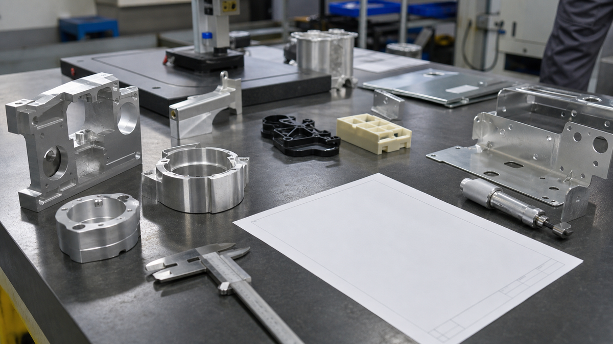
Surface finish is easy to treat as a small drawing note, but it can change how a CNC machined part is programmed, cut, finished, and inspected. A tighter finish may affect feeds, step-over, finishing passes, masking, secondary operations, and documentation.
For buyers, the useful question is not whether smoother is always better. The better question is which surfaces need controlled roughness for function, which surfaces need cosmetic control, and which surfaces can stay at a normal machined finish.
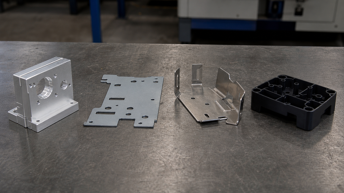
This article focuses on specification decisions that affect quoting, machining strategy, finishing, and inspection. It also separates CNC machining from CNC turret punching, metal stamping, sheet metal fabrication, and plastic injection molding so the RFQ is reviewed against the right process.
When Should Surface Finish Be Treated as a Functional CNC Machining Requirement?
Surface finish becomes a functional CNC machining requirement when it affects sealing, sliding, bearing contact, coating preparation, assembly fit, or visible acceptance. If a surface does not affect function or inspection acceptance, it can often remain at a normal machined finish.
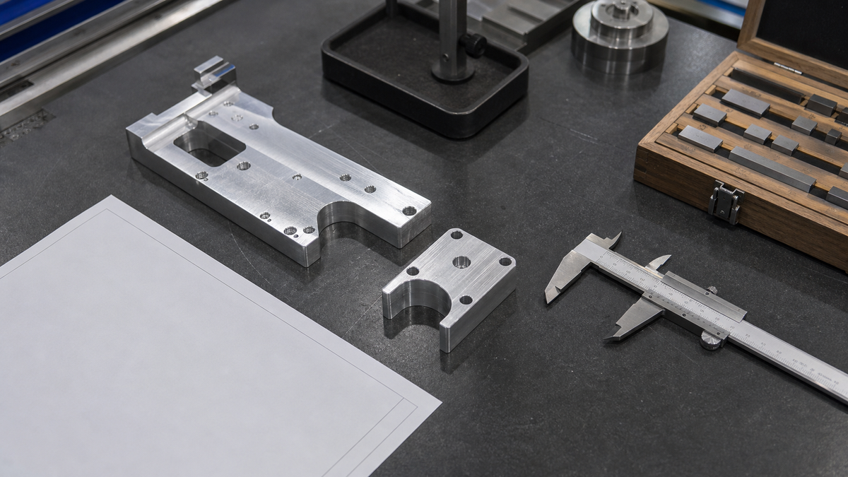
A useful surface finish callout starts with the job the surface performs. In CNC machining, a milled or turned face is shaped by the cutting tool, feed, step-over, tool condition, and finishing pass strategy. A surface roughness parameter1 such as Ra should therefore be tied to a surface that must function in a controlled way.
Before releasing the RFQ, separate the surfaces into practical groups:
- Functional surfaces: sealing faces, bearing journals, sliding lands, press-fit areas, mating faces, or coating-preparation surfaces.
- Cosmetic surfaces: visible areas where consistent appearance matters, even if roughness does not control mechanical function.
- Ordinary machined surfaces: pockets, clearance faces, lightening cuts, non-contact walls, and hidden areas with no special finish requirement.
What should the drawing actually say?
The drawing should identify the surface, the required finish, and the reason when it is not obvious from the design. A sealing land, for example, should not be buried under the same generic note used for clearance pockets.
Example: A cover plate may have one sealing land that needs controlled roughness, while the underside pocket only needs clean machining and deburring. Treating both surfaces the same can add machining and inspection effort without improving the part.
The strongest finish specification tells the supplier where finish matters, whether it is functional or cosmetic, and whether it must be measured or simply controlled as workmanship.
Is the RFQ Really for CNC Machining or Another Manufacturing Process?
The RFQ should confirm the intended process before surface finish is discussed. CNC machining removes material from stock, while CNC turret punching, sheet metal fabrication, metal stamping, and plastic injection molding create surfaces through different tooling, material behavior, and finish constraints.

Surface finish language becomes unreliable when different manufacturing processes are mixed together. CNC machining creates the surface by removing material through milling, turning, drilling, boring, reaming, and related operations. The finish is affected by tool path, tool engagement, cutting parameters, tool access, and finishing passes.
That is different from sheet, die, and mold-based processes. CNC turret punching uses programmed punch tools on sheet metal. A CNC punch press can produce holes and profiles, but it does not create a machined surface from solid stock. Metal stamping uses dedicated dies and brings different concerns, including burr direction and springback2. Sheet metal fabrication may combine cutting, punching, bending, welding, and finishing. Plastic injection molding forms polymer parts in a mold, where surface texture is tied to mold finish, resin flow, draft, gate location, and part release.
| Process term | What it usually means | Finish and inspection focus |
|---|---|---|
| CNC machining | Material removal from solid stock | Tool paths, feeds, passes, Ra, deburring, secondary finish |
| CNC turret punching or CNC punch press | Programmed punching of sheet metal | Punch marks, burr direction, edge quality, sheet finish |
| Metal stamping | Dedicated die forming or blanking | Die surface, forming marks, burrs, springback, production volume |
| Sheet metal fabrication | Cutting, punching, bending, welding, finishing | Edges, bends, weld finish, coating, visible faces |
| Plastic injection molding | Polymer shaped in a mold | Mold texture, resin flow, draft, gate location, cosmetic standards |
If an RFQ says CNC turret punching, CNC punch press, CNC-controlled stamping equipment, or metal stamping depending on the actual process, clarify it before quoting. It may mean CNC turret punching, CNC-controlled stamping equipment, sheet metal fabrication, or general die stamping.
Where Can a Standard Machined Finish Control Cost Without Hurting Function?
A standard machined finish can control cost on surfaces that do not seal, slide, locate, bear load, receive critical coating, or define visible acceptance. Finer Ra values should be reserved for surfaces where roughness affects function, appearance, or inspection acceptance.
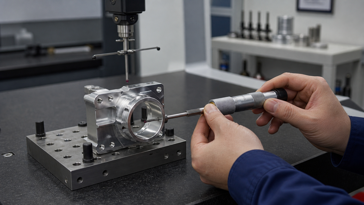
A practical CNC drawing does not make every surface carry the same finish burden. The supplied research identifies Ra 3.2 micrometers3 as a common economical reference and Ra 1.6 to 3.2 micrometers as a practical range for many commercial CNC machined parts. Those values still need context; the real decision is whether the surface affects the part’s function or acceptance.
When a fine finish is applied everywhere, the supplier may need slower cutting, extra finishing passes, tighter process control, and broader inspection. That can be justified on a sealing component, but it is often wasteful on clearance pockets, hidden side walls, or non-contact faces.
| Surface type | Specification decision | Practical consequence |
|---|---|---|
| Sealing face | Call out required Ra and inspection need | May require controlled finishing and roughness verification |
| Bearing journal or sliding area | Define roughness and tolerance together | Can affect turning, polishing, and measurement planning |
| Cosmetic visible face | Define appearance separately from function | May need consistent tool marks or secondary finish |
| Internal clearance pocket | Usually leave as normal machined finish if non-critical | Avoids unnecessary finishing and roughness checks |
| Non-contact side wall | Use the general finish unless function says otherwise | Keeps machining and inspection focused |
Example: A machined housing may need controlled roughness on an O-ring gland face, but not on every pocket floor. The RFQ should show that difference clearly so the supplier quotes the actual acceptance requirement, not a blanket finish assumption.
How Should Fine Finish Zones Be Localized on a CNC Drawing?
Fine finish zones should be localized with finish symbols, detail views, notes, or marked boundaries that identify the controlled area. This lets the supplier machine and inspect critical surfaces without treating the entire part as a fine-finish requirement.
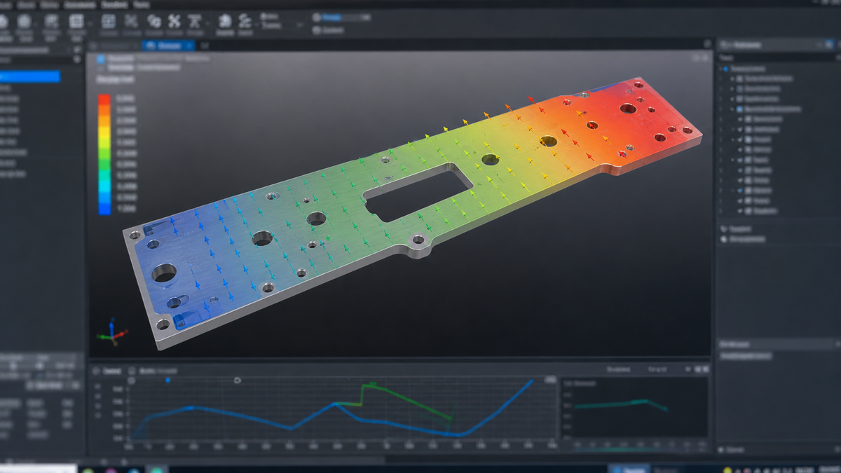
Localizing a fine finish requirement is one of the cleanest ways to control CNC machining cost without weakening the design intent. The drawing should show which surface needs the finish, where the finish starts and ends, and whether the requirement applies before or after any secondary operation.
A finish note placed near the title block can be interpreted broadly unless it is clearly written as a default. For critical surfaces, point the note to the actual face, bore, journal, groove, or land. Detail views help when the controlled area is small, hidden, or close to other geometry.
Scenario: A shaft has a bearing journal, a clearance shoulder, and a threaded end. Only the bearing journal needs controlled roughness. If the same fine finish is applied to the full shaft, the supplier may quote extra finishing and inspection on the shoulder and thread area even though they do not carry the bearing function.
A clear localization package can include:
- Surface finish callout on the exact controlled face or diameter.
- Detail view for grooves, sealing lands, or narrow journals.
- Boundary dimensions4 showing the length or area of the finish zone.
- Note stating whether roughness measurement is required.
- Separate cosmetic note for visible surfaces that are not function-critical.
- Masking note if anodizing, plating, bead blasting, or polishing must avoid selected faces.
Fine finish zones should follow function. When the drawing makes the zone visible, the supplier can plan tool paths, finishing steps, and inspection coverage with fewer assumptions.
How Does a Lower Ra Requirement Change CNC Machining Strategy?
A lower Ra requirement can change feeds, step-over, tool condition, finishing passes, setup planning, and inspection effort. The buyer’s decision is whether the smoother surface is needed for function or whether it only adds control to non-critical areas.
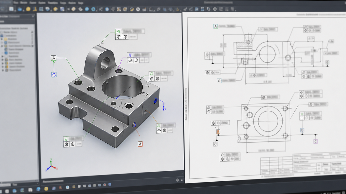
Surface roughness is produced through machining choices. A lower Ra usually pushes the supplier toward a finishing strategy with smaller step-over, slower feed, controlled tool engagement, and additional passes. A small radial step-over5 may improve the surface on a milled face, but it also increases the amount of tool path required on that area.
Geometry can make the same finish callout easy or difficult. A broad flat face with open tool access is not the same as a deep pocket, thin wall, narrow groove, or surface near a small internal radius. Thin walls can deflect under cutting force. Deep pockets may limit tool stiffness and chip evacuation. Features on multiple sides may require repositioning, so the supplier has to protect dimensional relationships and surface condition across setups.
When does fine finish become a real cost driver?
Fine finish becomes more demanding when it covers a large area, sits inside difficult geometry, or must be held together with tight dimensional tolerance. It also becomes more demanding when the surface will later be polished, plated, anodized, or otherwise treated.
For quoting, the buyer should identify the functional reason for each lower Ra value. Sealing, sliding, and bearing contact are stronger reasons than a general preference for smoothness. Cosmetic expectations should be written as cosmetic requirements unless roughness measurement is truly the acceptance method.
The machining route may move from roughing and ordinary finishing to roughing, semi-finishing, finishing, careful deburring, secondary finishing, and documented inspection. That is why roughness belongs in the same discussion as geometry, tolerance, setup risk, and production intent.
Which Secondary Finishing Steps Should Be Quoted Separately?
Secondary finishing should be quoted separately when the required surface cannot be defined by normal CNC cutting alone. Grinding, lapping, polishing, bead blasting, anodizing, plating, and similar treatments can affect handling, masking, dimensions, inspection, and acceptance.
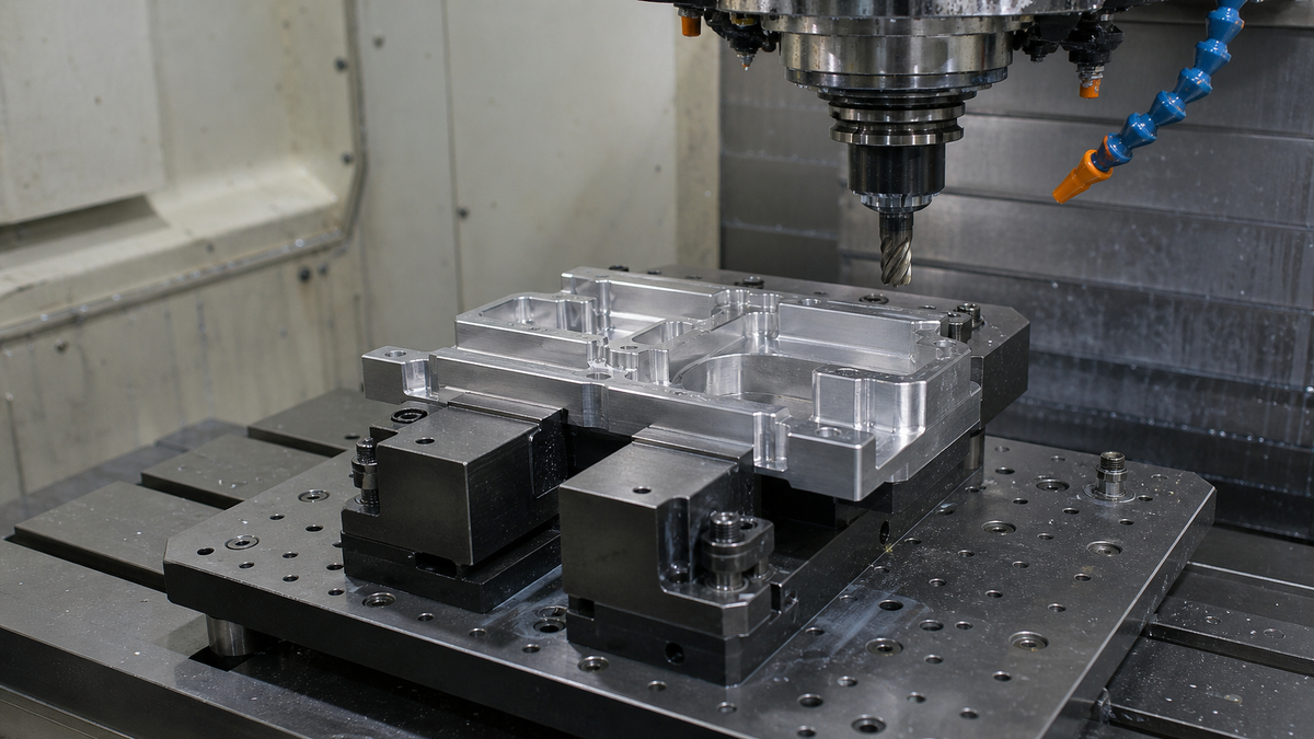
Some surface requirements are not just machined finish requirements. They are post-machining operations. If the RFQ expects grinding, lapping, polishing, bead blasting, anodizing, plating, or another treatment, list that requirement separately from machining and tie it to the surfaces involved.
Secondary finishing can change the process route. Parts may need handling protection, cleaning, masking, outside processing, dimensional allowance, or inspection after finishing. Finish buildup6 can also affect the acceptance condition if the drawing does not say whether dimensions apply before or after the applied finish.
| Secondary finish | Why it may be specified | RFQ detail to define |
|---|---|---|
| Grinding | Controlled flatness, size, or surface condition on selected areas | Surface location, tolerance relationship, inspection requirement |
| Lapping | Controlled contact or sealing surface | Exact area, function, and acceptance method |
| Polishing | Cosmetic or functional smoothing | Localized areas, surfaces to avoid, inspection expectation |
| Bead blasting | Uniform cosmetic texture or coating preparation | Exposed faces, masked faces, visual expectation |
| Anodizing or plating | Surface protection, appearance, or functional surface change | Material, finish type, masking, before or after finish dimensions |
Secondary finishing should also be separated from deburring and edge break. Deburring removes sharp or loose edges; it does not automatically define a controlled Ra value. Edge break and chamfer notes should be clear enough that the supplier understands both handling safety and dimensional acceptance.
If finishing is functional, say so. If it is cosmetic, say so. That distinction prevents many inspection disputes.
How Should Material Choice Be Matched With the Required Finish?
Material grade and condition should be specified before surface finish is quoted because material affects machinability, surface response, coating compatibility, sourcing assumptions, and inspection planning. A finish that suits one material may need different assumptions on another.
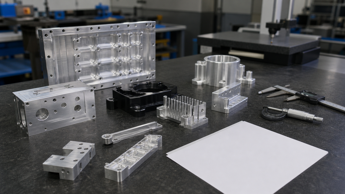
The RFQ should not say only aluminum, steel, stainless, brass, or plastic when surface finish matters. It should identify the material grade and condition because the supplier must judge how that material will machine, how it may respond to finishing, and whether the requested post-treatment is suitable for the intended result.
Material affects burr behavior, cutting stability, tool wear assumptions, achievable appearance, and coating compatibility. If the buyer expects anodizing, plating, polishing, bead blasting, or another finish, material and finish should be reviewed together rather than treated as independent notes.
A practical material-and-finish review should ask:
- What material grade and condition are required?
- Is the material selected for strength, corrosion behavior, weight, conductivity, appearance, or cost?
- Will the surface be used for sealing, sliding, bearing, or coating preparation?
- Does the finish apply before or after final dimensional inspection?
- Are any surfaces masked, uncoated, or left as-machined?
- Does geometry create finishing risk, such as deep pockets, thin walls, sharp internal corners, or narrow grooves?
- Is the order a prototype, pilot run, or production part?
A visible machined cover, for instance, may need a consistent cosmetic face and a different functional finish on a gasket surface. The material grade, machining direction, bead blast or anodize expectation, and masking notes should be reviewed together so appearance does not interfere with sealing.
Material selection is part of the finish specification, not background information.
Should Dimensions Be Controlled Before or After Surface Finishing?
The drawing should state whether dimensions apply before finishing, after finishing, or only on selected tolerance-critical surfaces. Applied finishes and additional polishing or cutting can change surface condition, material removal assumptions, and final inspection criteria.
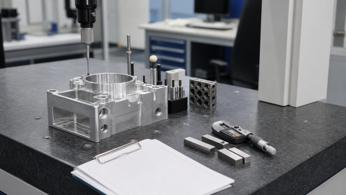
Surface finish and dimensional tolerance are connected. A machined surface may meet size before coating, while the accepted part may be inspected after anodizing, plating, polishing, or another treatment. If the drawing does not state the inspection condition, the buyer and supplier may build different assumptions into the quote.
Scenario: A plate has a tight mating thickness and will receive an applied finish. If the drawing gives the thickness tolerance but does not say whether it applies before or after finishing, the supplier must guess how to plan machining allowance, finishing, and final inspection. That uncertainty can create tolerance stack-up7 questions, quote exceptions, or acceptance disputes.
The drawing should define:
- Which dimensions are critical to function.
- Whether dimensions apply before finish, after finish, or both in selected places.
- Which surfaces receive coating, plating, bead blasting, polishing, or grinding.
- Which surfaces must remain uncoated, unpolished, or masked.
- Whether roughness measurement is required before or after the secondary finish.
- Whether GD&T controls such as flatness, position, perpendicularity, parallelism, or profile apply to the final condition.
Which tolerances need this clarification most?
Clarification matters most on bearing fits, dowel holes, sealing faces, press-fit areas, mating faces, threaded features, and surfaces with coating or polishing. It also matters on thin walls and broad plates because small material changes can influence final fit or flatness.
A good RFQ states what the finished part must satisfy and which intermediate conditions matter.
What Inspection Scope Should Be Defined Before Quoting Surface Finish?
Inspection scope should be defined before quoting because surface finish can require more than visual review. The RFQ should state whether dimensional checks, roughness readings, first article inspection, CMM reports, material documentation, sampling, or selected full inspection are required.
Inspection is part of the manufacturing plan. A finish note that says smooth is different from a drawing that requires documented roughness readings on selected surfaces. The supplier needs to know what must be checked, how often it must be checked, and whether records must ship with the parts.
Inspection scope should match risk. A hidden clearance pocket may need only ordinary workmanship review and deburring. A sealing face with a specified Ra may require roughness measurement. A mating face with flatness and surface finish requirements may require both dimensional and surface condition review.
| Requirement type | Possible inspection approach | RFQ question to answer |
|---|---|---|
| Visual cosmetic expectation | Visual review against agreed appearance notes | What surface variation is unacceptable? |
| General machined surfaces | Basic dimensional checks and workmanship review | Are roughness readings required or not? |
| Critical Ra surface | Roughness measurement on selected zones | Which surfaces, what frequency, and with records? |
| Tight dimensional relationship | Dimensional report or CMM report if required | Which features and datums control acceptance? |
| First production lot | First article inspection if required | Does it apply once, each revision, or each shipment? |
| Material traceability | Material documentation if required | What material evidence must be supplied? |
Do not ask for full inspection by habit. It may be justified for selected critical features, but it should be tied to function and risk. Sampling, first article, and full dimensional reporting are different levels of effort.
The most useful RFQ language identifies the specific surfaces and features that must be measured and recorded.
Why Do Blanket Fine-Finish Notes Create Cost and Acceptance Risk?
Blanket fine-finish notes create risk because they apply one requirement to surfaces with different functions. They can increase machining, finishing, and inspection effort while leaving unclear whether the buyer means functional roughness, cosmetic appearance, or ordinary workmanship.
A blanket fine-finish note may look efficient, but it often hides the real requirement. If the entire part is marked with one fine Ra value, the supplier may have to treat pocket floors, side walls, clearance areas, non-contact faces, cosmetic faces, and sealing surfaces as if they all carry the same acceptance risk.
That creates two problems. First, the quote may include unnecessary finishing and inspection. Second, the buyer and supplier may disagree later about what the note was meant to control. A cosmetic concern should not be written as a functional roughness requirement unless roughness measurement is truly the acceptance method.
Scenario: A machined enclosure has a visible top face, internal pockets, tapped holes, and one gasket surface. The buyer wants the top face to look consistent and the gasket surface to seal. One fine-finish note across the whole drawing does not explain that difference. The better drawing separates the top face cosmetic expectation, the gasket face Ra requirement, and the ordinary machined finish for internal pockets.
Common specification mistakes include:
- Applying one fine Ra value to every surface.
- Using words such as smooth or polished without defining where they apply.
- Mixing cosmetic appearance with sealing or sliding function.
- Forgetting to say whether roughness must be measured and recorded.
- Not identifying surfaces that will be coated, masked, or left uncoated.
- Treating deburring as if it automatically controls surface roughness.
A better finish note is selective. It tells the supplier which surfaces matter, how they will be accepted, and which areas can remain at the general machined finish.
What RFQ Information Lets a Supplier Price Surface Finish and Inspection Correctly?
A complete RFQ gives the supplier the model, drawing, material, quantity, production intent, revision, delivery expectations, finish locations, tolerance requirements, masking needs, and inspection documentation. Without these details, finish cost and inspection scope are quoted with assumptions.
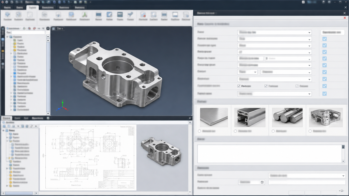
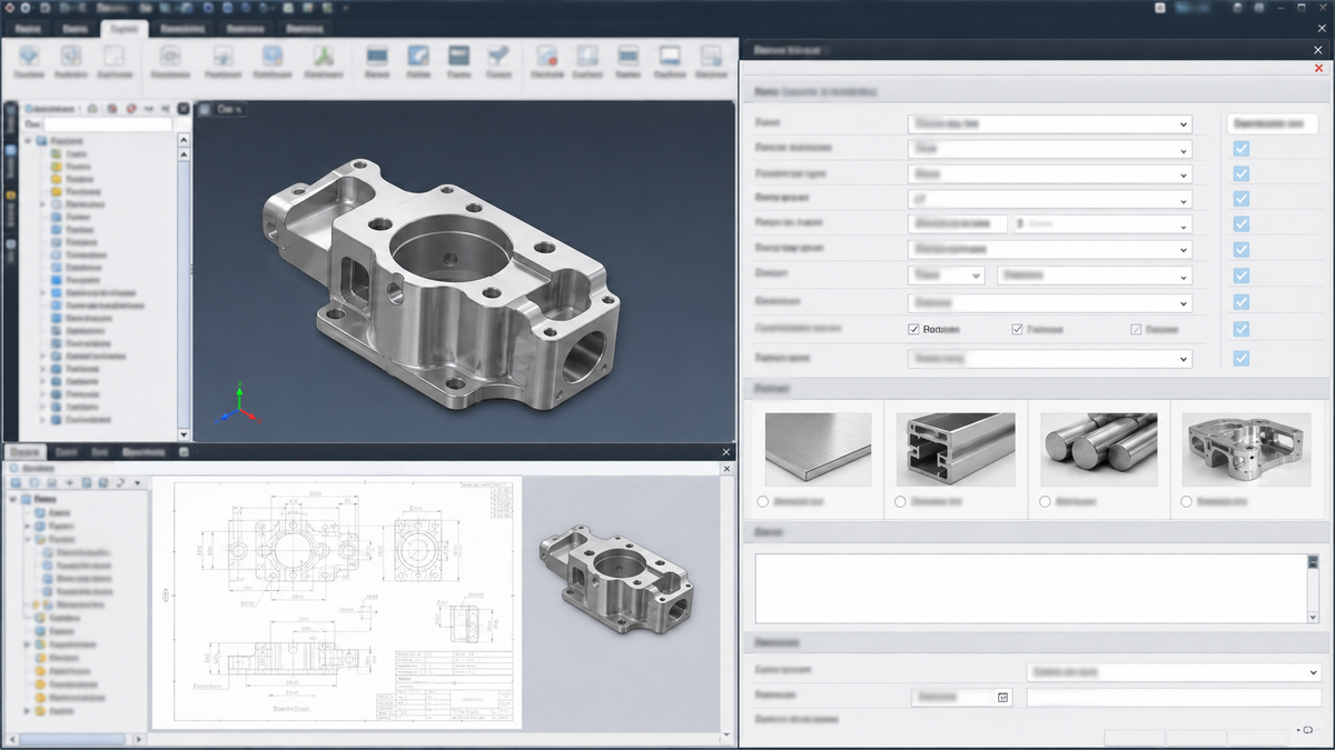
The best surface finish discussion happens before price is finalized. A supplier can review machining, finishing, and inspection more accurately when the RFQ package shows both geometry and acceptance requirements. The 3D model helps with tool access, setup planning, pocket depth, wall thickness, and overall manufacturability. The controlled 2D drawing8 communicates tolerances, surface finish, revision, notes, and inspection requirements.
Use this RFQ checklist before requesting price:
- 3D CAD model for geometry review.
- Controlled 2D drawing with active revision level.
- Material grade and condition.
- Quantity for the immediate order.
- Prototype, pilot, or production intent.
- Estimated annual usage if known.
- Required delivery timing and partial shipment expectations if relevant.
- Critical tolerances and GD&T controls.
- Surface finish values and exact finish locations.
- Surfaces that can remain at standard machined finish.
- Secondary operations such as anodizing, plating, bead blasting, polishing, grinding, lapping, laser marking, deburring, edge break, or assembly.
- Masking requirements and surfaces that must remain uncoated or unpolished.
- Whether dimensions apply before or after finishing.
- Required inspection method and documentation, including roughness readings, dimensional reports, CMM reports, first article inspection, sampling, full inspection of selected critical features, or material documentation.
- Acceptance priority if the model and drawing disagree.
A complete RFQ does not guarantee one quote outcome, but it reduces guessing. It lets the supplier price the real plan: material sourcing, setup, machining passes, finishing route, inspection time, reporting effort, and schedule risk.
For surface finish, missing information usually becomes an exception later. Define it before the supplier commits to price and delivery.
For a surface finish recommendation, sample review, or quotation, send the 3D model, controlled 2D drawing, material grade, quantity, revision level, prototype or production intent, critical tolerances, finish values and locations, inspection expectations, and delivery requirements. Also state whether dimensions apply before or after finishing.
References
-
Surface Roughness Top Ten - Michigan Metrology - Average Roughness is the most widely specified parameter for controlling surface roughness. It's represented by Ra for two-dimensional (profile) measurements, ... ↩
-
Metal Stamping Guide: Processes, Tooling, and DfM - Fictiv - Burr Direction: Specify the required burr orientation (up or down). The burr always forms on the side of the material facing the die block. ↩
-
Surface Roughness Conversion Chart Tables - Engineers Edge - The following charts and tables convert surface finish or roughness between selected industry standard units. , average in micro-meters 3.2 0.8 1.25 6.30 ↩
-
Surface Finish Symbols & Callouts on Engineering Drawings (ISO ... - Define the boundary clearly using dimensions or a partition line, and have each roughness symbol point to its corresponding region. This ... ↩
-
CNC Stepover Guide: Understanding Its Impact on Surface Finish ... - Extremely small stepovers may increase machining time significantly without a proportional improvement in surface roughness (often quantified as ... ↩
-
How Anodizing Affects Dimensions | Build-Up vs Penetration - Learn how anodizing affects aluminum dimensions, including buildup and penetration ratios for Type I, II, and III anodizing. Expert guide from Anoplate in ... ↩
-
Tolerances to apply before or after anodising? - Eng-Tips - "Where a part is to be plated or coated, the drawing or referenced document shall specify whether the dimensions apply before or after plating. ↩
-
CNC Machining RFQ Template Guide - uneed - The package typically starts with a 3D CAD model, often a STEP file, and a 2D PDF drawing that defines tolerances, GD&T, notes, surface finish, and material ... ↩