
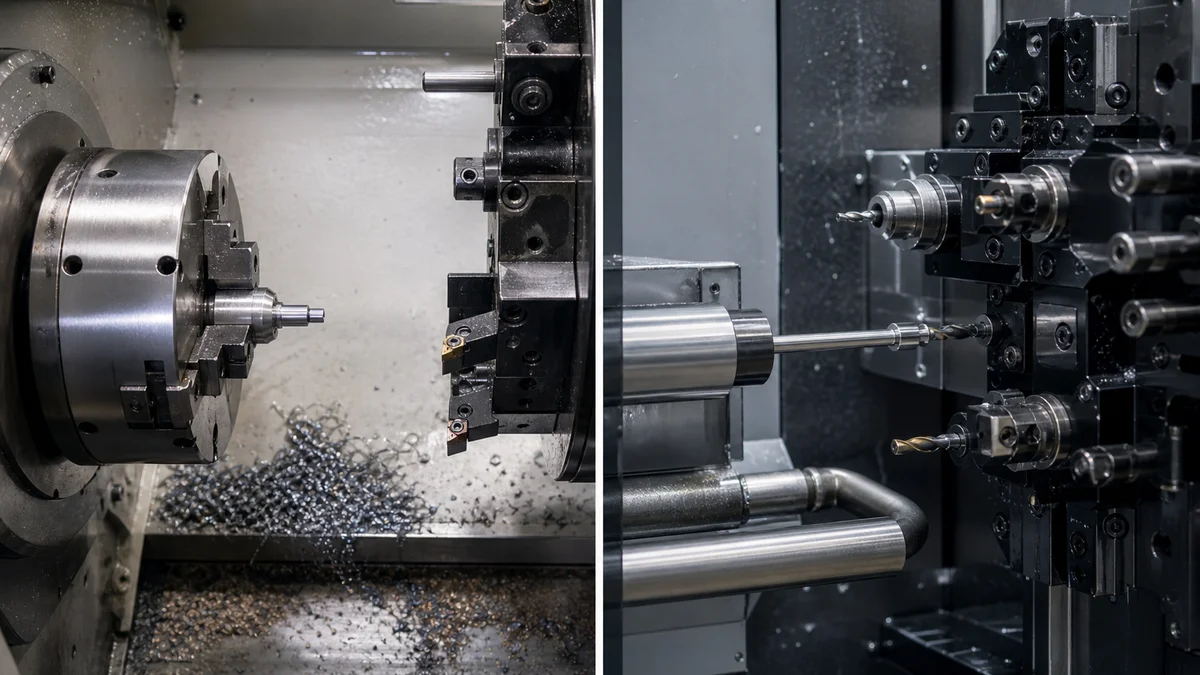
Choosing between conventional CNC turning and Swiss machining involves more than checking the finished diameter. The practical decision starts with how the stock is supported, which sections are exposed to cutting forces, and whether critical features can be completed without transferring the part between setups.
Conventional turning often suits short, rigid parts and straightforward rotational geometry. Swiss machining becomes more relevant when a bar-fed component combines slender sections, closely related turned and off-axis features, or stable repeat demand.
The right route depends on geometry, material, tolerance, surface finish, inspection scope, quantity, and production intent. The following comparison turns those inputs into specific RFQ and process-approval decisions.
How Does Workpiece Support Change the Process Choice?
Choose Swiss machining when a long, slender part needs support close to the cutting point to limit bending or vibration. Conventional CNC turning may be more direct when a chuck or collet can hold a short, rigid workpiece without creating a significant unsupported section.
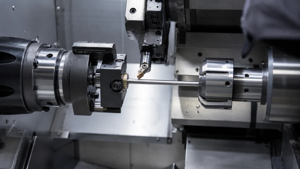
The fundamental difference is where the workpiece is supported. In conventional turning, a chuck or collet grips the blank while the cutting tool works on material extending from that holding point. As the exposed length increases, rigidity decreases and cutting forces can bend the stock or generate chatter.
A Swiss machine feeds bar stock through a guide bushing, with cutting performed close to that support. This guide-bushing support principle1 can help stabilize long, small-diameter sections, but it does not make Swiss machining automatically preferable for every small component.
| Specification factor | Conventional CNC turning | Swiss machining | Buyer implication |
|---|---|---|---|
| Workpiece support | Chuck or collet behind exposed work | Guide bushing near the cut | Compare the actual unsupported cutting length |
| Natural geometry fit | Short, rigid rotational profiles | Slender, bar-fed profiles | Review every reduced section, not only overall size |
| Primary stability risk | Deflection as stick-out increases | Bar-to-bushing compatibility | Supply stock size and condition |
| Common selection reason | Direct setup for compact geometry | Support near long, reduced diameters | Tie the choice to critical features |
The drawing should show the complete turned profile. Long journals, grooves, thin necks, extended threads, and abrupt diameter changes can determine the effective unsupported length. A large shoulder may also limit how closely the tool can work to the support point.
Start by identifying the distance from the holding or support point to each critical cut. Then consider material stiffness, cutting forces, tolerance, surface finish, and quantity. That sequence reveals whether extra support addresses a real manufacturing risk or merely adds process complexity.
When Does Part Slenderness Favor Swiss Machining?
Review Swiss machining when overall length, minimum diameter, and unsupported cutting length create a slender feature that may deflect. Length-to-diameter ratios above roughly 3:1 or 4:1 are useful screening signals, not universal limits or guaranteed process thresholds.
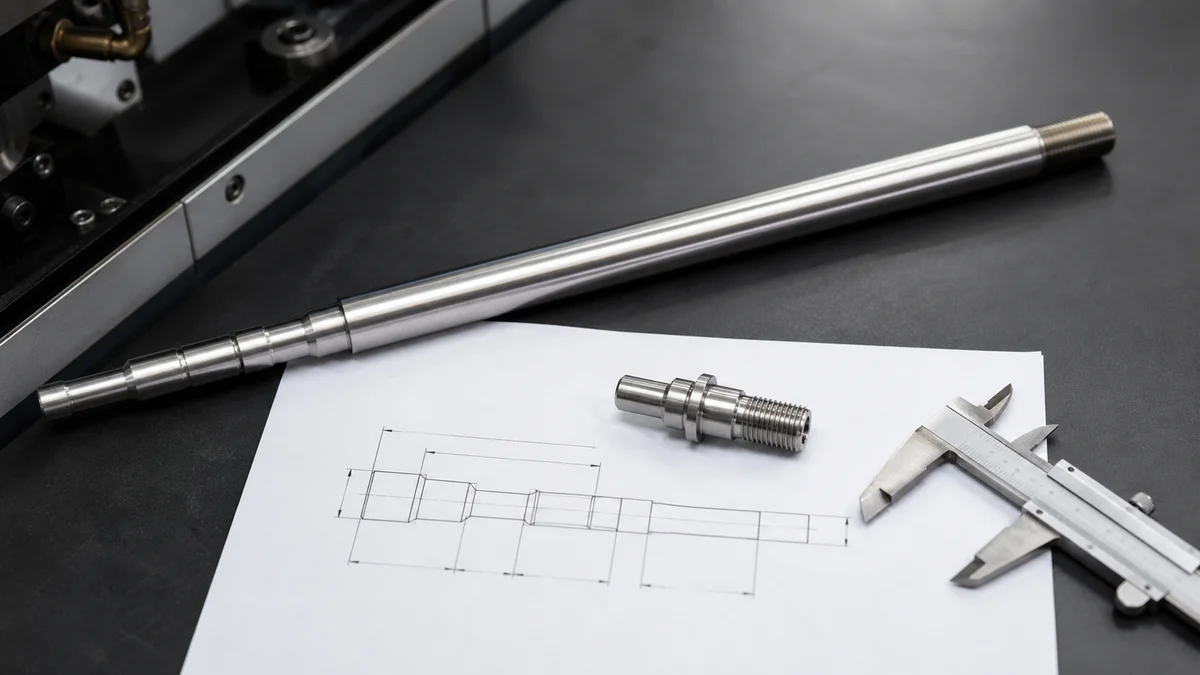
Length-to-diameter ratio, usually written as L/D, compares a relevant unsupported length with its diameter. For process selection, calculate it from the section exposed to cutting forces—not automatically from the overall part length or maximum stock diameter.
Use this initial review:
- Record the overall part length.
- Identify every reduced diameter.
- Measure the longest unsupported section at each diameter.
- Note grooves, undercuts, threads, and shoulders that reduce stiffness.
- Mark surfaces where chatter, straightness, runout, or finish affects function.
Ratios above approximately 3:1 or 4:1 are useful length-to-diameter screening guidelines2, particularly for small-diameter work. They are prompts for supplier review rather than universal machine limits. Material stiffness, cutting forces, tool engagement, stock condition, and surface requirements can change the practical result.
Scenario: A teaching part has a broad mounting head and a long narrow stem. Calculating L/D with the head diameter makes the component appear rigid, but the stem is exposed during the critical cut. Its diameter and unsupported length provide the useful ratio. If the stem contains a bearing fit, thread, or finish-critical journal, guide-bushing support deserves closer consideration.
A low L/D ratio does not automatically select conventional turning. Cross-holes, flats, or second-end features may independently support a Swiss route. Conversely, a moderately slender feature in readily machinable stock may remain suitable for conventional turning if its tolerances and finish are forgiving. Use the ratio to identify risk, then select the process from the complete geometry.
Does the Diameter and Bar Stock Fit a Swiss Machine?
Swiss machining fits small components most naturally when their complete profile can be produced from suitable continuous bar stock. Confirm the maximum shoulder, minimum diameter, stock condition, straightness, and machine envelope; a small nominal diameter alone does not establish a good Swiss application.
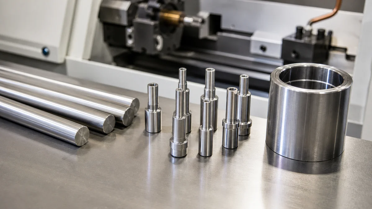
Swiss process fit depends on the incoming bar, guide bushing, complete feature envelope, and feeding behavior working together. A profile with one small journal but a much larger shoulder may gain less from Swiss machining than a consistently slender part.
Before prescribing the route, document:
- Maximum finished diameter and every major shoulder
- Minimum diameter and length of each reduced section
- Starting bar diameter and required stock form
- Bar straightness or consistency requirements affecting feed
- Interrupted cuts, broad flats, or other changes in tool engagement
- Overall length, cutoff allowance, and second-end features
- Material source restrictions or documentation requirements
Large shoulders and short, stub-like geometry can reduce the benefit of support near the cut. Interrupted cuts can change cutting forces, while nonstandard or inconsistent stock may not feed predictably. Conventional turning may therefore be more direct when the blank is compact, unsuitable for continuous feeding, or substantially larger than its few small features suggest.
The RFQ should provide the full profile and request confirmation of the supplier's usable Swiss working envelope3. It should not assume that one published diameter capacity applies to every feature, stock condition, or tooling arrangement.
Use the 3D model to communicate the complete geometry and the controlled 2D drawing to define maximum and minimum diameters, tolerances, stock restrictions, units, and revision. Those files let suppliers compare bar utilization, guide-bushing fit, cutoff strategy, remnant material, and conventional chucking without guessing from the phrase “small turned part.”
How Should Material and Stock Condition Affect the Choice?
Specify the exact material grade, condition, and stock form before choosing the machine route. Machinability, chip formation, cutting force, heat sensitivity, bar availability, and stock consistency interact with slenderness, so neither conventional turning nor Swiss machining is universally superior across materials.
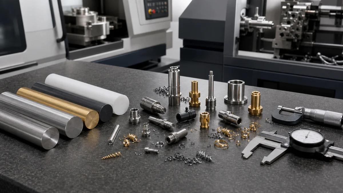
Material affects how the workpiece cuts and how reliably it feeds through the selected setup. Labels such as “stainless steel,” “aluminum,” or “plastic” leave essential assumptions unresolved. Grade, temper, hardness, conditioning state, and stock form can alter chip behavior, cutting force, heat generation, stability, and sourcing.
Long, stringy chips can complicate automated cutting. Higher cutting forces can make a slender section more sensitive to support, while some engineering plastics may respond strongly to heat or clamping pressure. These factors do not automatically select Swiss machining, but they influence the value of guide-bushing support and the process control required.
What material information belongs in the RFQ?
State the exact grade and condition, permitted alternatives, required bar form, and any mandatory material evidence. If the buyer supplies the stock, identify that responsibility and give its diameter, length, and condition. For plastics affected by moisture or thermal conditioning, define the state in which dimensions will be inspected and accepted.
Availability also matters. A preferred route can become impractical when the specified grade is unavailable in a consistent bar diameter. Ask the supplier to confirm bar-stock availability and consistency4 instead of assuming that a catalogued material is stocked in the required form.
Material selection and machine selection are separate decisions, but they must be evaluated together. Communicate final geometry, tolerances, finish, service conditions, and inspection expectations. Let the supplier plan tooling, chip control, support, and cutting strategy unless a manufacturing method is functionally mandated.
Which Feature Set Justifies Swiss Machining or Conventional Turning?
Conventional turning may suit a short part dominated by facing, boring, grooving, drilling, threading, and parting. Swiss machining becomes more compelling when a small bar-fed component also needs cross-holes, flats, slots, or second-end work that can be completed without separate reclamping.
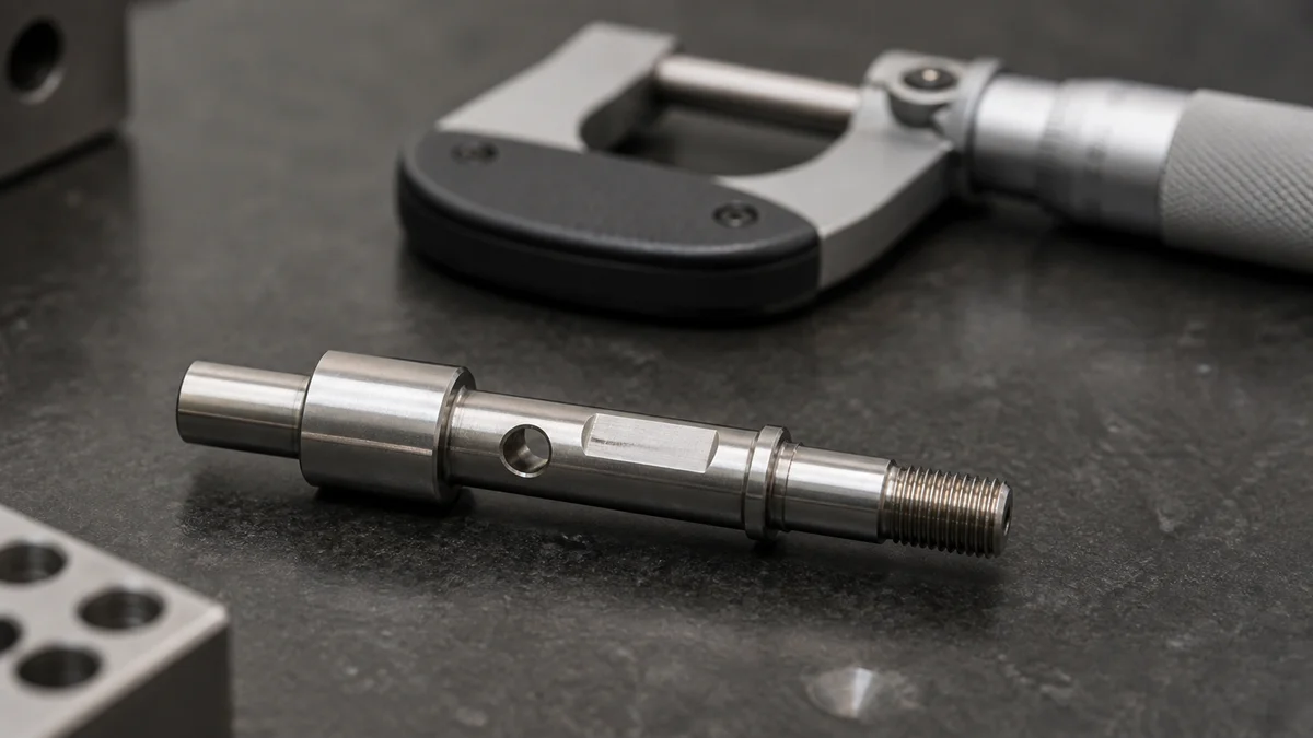
Process selection should cover the complete feature set, not only the outside profile. A simple rotational component may be produced directly on a conventional lathe. A part combining turned surfaces with off-axis or back-side details may benefit from live tooling, a sub-spindle, and back-working when the proposed Swiss configuration supports them.
| Feature requirement | Conventional turning may fit when | Swiss machining may fit when | Drawing information needed |
|---|---|---|---|
| Facing, boring, grooving | The part is short and rigid | These operations accompany slender sections | Depths, diameters, and critical shoulders |
| Cross-holes or flats | A secondary setup is acceptable | One-cycle alignment reduces transfer risk | Position relative to the turned axis |
| Second-end details | Rechucking does not threaten function | A sub-spindle can complete the back end | End-face datum and feature relationships |
| Slots or milled details | Separate milling is economical | Live tooling reaches all required features | Tool-access direction and slot geometry |
| Related cylindrical features | Controlled reclamping is adequate | One cycle protects alignment | Runout, position, or coaxiality requirements |
Example: Consider a teaching shaft with two bearing diameters, a cross-hole, wrench flats, and a threaded second end. If the cross-hole and flats must remain closely related to the turned axis, multiple setups create datum-transfer and inspection risk. A one-cycle machining strategy5 may be attractive. If those relationships are loose and the order is an early prototype, conventional turning followed by milling may remain more flexible.
Identify which relationships control assembly. Use functional datums and GD&T where position or runout matters, and state whether secondary machining is acceptable. Otherwise, suppliers cannot compare setup count on equivalent assumptions.
Which Tolerances and Inspection Requirements Drive Process Selection?
Let functional tolerances and inspection requirements influence the route, but do not treat Swiss machining as a guarantee of conformance. Identify critical diameters, runout, coaxial or positional relationships, datums, measurement conditions, inspection frequency, and required reports for the actual material, geometry, and quantity.
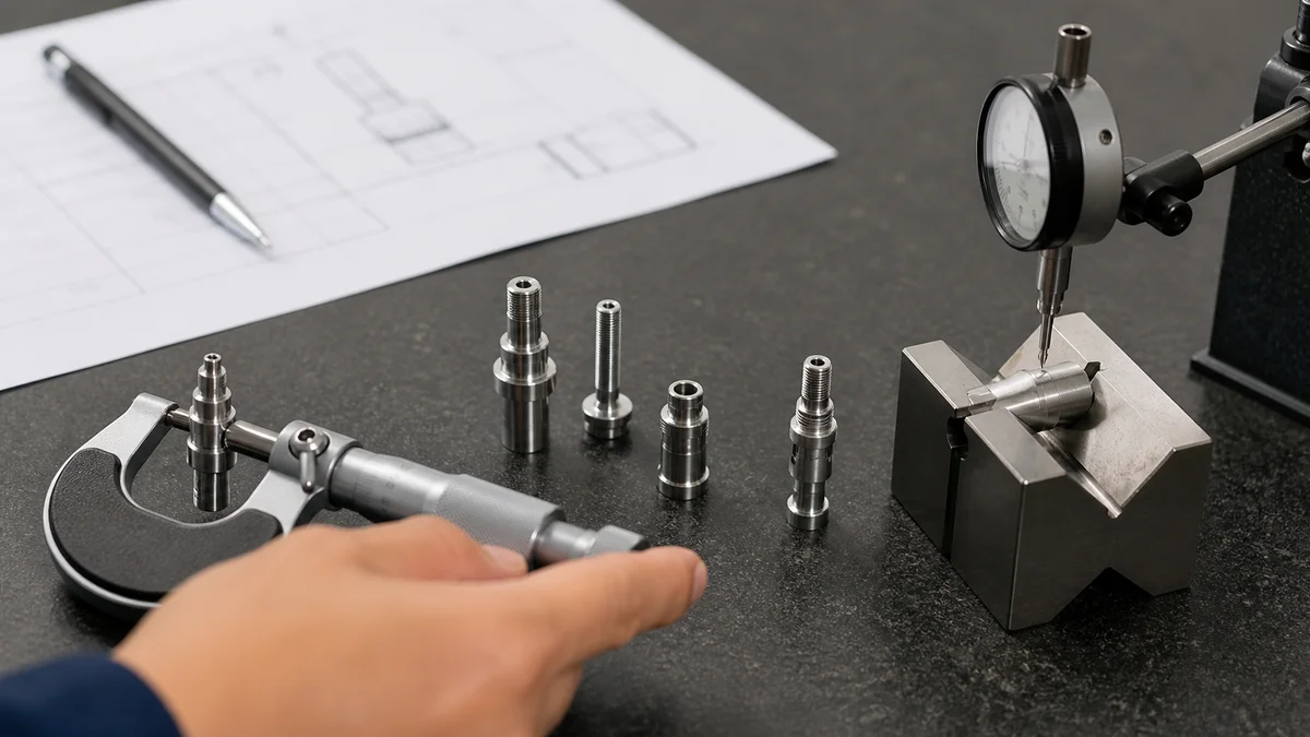
Small precision parts often contain a few characteristics that control assembly while the remaining geometry is ordinary. Separate these groups instead of applying one close tolerance to every diameter and length.
Features requiring focused review may include:
- Bearing journals and fitted diameters
- Sealing surfaces and locating shoulders
- Runout between related diameters
- Coaxial or positional relationships
- Cross-hole position relative to the turned axis
- Threads or grooves located from a functional face
Guide-bushing support can improve stability on slender features, but repeatability also depends on material, tool condition, setup strategy, finishing, and measurement. Request a feature-specific repeatability assessment6 for the actual geometry and batch rather than relying on a general process claim.
GD&T is useful when relationships govern function. Establish datums that reflect assembly—often a primary axis and locating face—then apply runout, position, or another appropriate control only where needed. Tightening a diameter does not control its relationship to another feature and can increase machining and inspection without protecting assembly.
Inspection scope should answer four questions: what is measured, how often, what evidence is delivered, and under what condition acceptance occurs. Depending on production intent, the RFQ may require first-article results, batch sampling, final dimensional reporting, or documented checks of selected critical features. The measurement method should match feature geometry and risk rather than being prescribed uniformly.
Define this scope before quotation. Adding reports or increased inspection frequency after machining has been priced creates avoidable gaps in schedule and cost assumptions.
When Should Surface Finish Influence the Machine Choice?
Surface finish should influence process selection only when specific surfaces have a functional or controlled cosmetic requirement. Swiss support may reduce bending and chatter on slender features, but material, tooling, access, cutting strategy, secondary finishing, and inspection still determine the delivered surface condition.
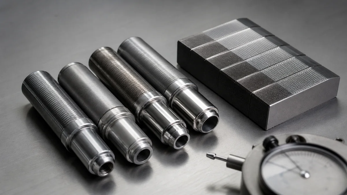
A general request for a smooth part is not enough to select a machine. Surface finish should support sealing, sliding, bearing contact, controlled friction, coating preparation, or a defined visual requirement. The drawing must identify the applicable surface and measurable or visual acceptance condition.
On a slender journal, support near the cut may reduce movement that contributes to chatter or an inconsistent tool path. That can make Swiss machining relevant. A short, rigid journal may reach the required condition through conventional turning without the additional setup burden. Compare the finish requirement together with diameter, unsupported length, material, and tool access.
Ra describes average surface roughness, but it does not independently control scratches, waviness, isolated marks, or lay direction. Cosmetic surfaces therefore may need separate visual criteria. A sealing or sliding surface may also require dimensional tolerance, runout control, and a defined roughness measurement location.
Example: A drawing applies one fine-finish note to an entire shaft, although only one sealing land contacts the assembly. That blanket instruction expands finishing and inspection across threads, grooves, shoulders, and non-contact diameters. A localized surface roughness callout7 lets the supplier control the sealing land while machining ordinary regions more efficiently.
State whether grinding, polishing, coating, or another secondary operation is permitted. If the operation removes material or adds finish buildup, define whether critical dimensions apply before or after treatment. Surface condition, dimensional acceptance, and inspection timing must all refer to the same delivered state.
How Do Setup Cost, Quantity, and Revision Risk Change the Decision?
Conventional turning may be more flexible for prototypes, uncertain demand, and frequently changing designs. Swiss machining may become more economical when stable repeat orders can distribute its programming, tooling, guide-bushing, and setup effort, but no universal quantity breakpoint should determine the choice.
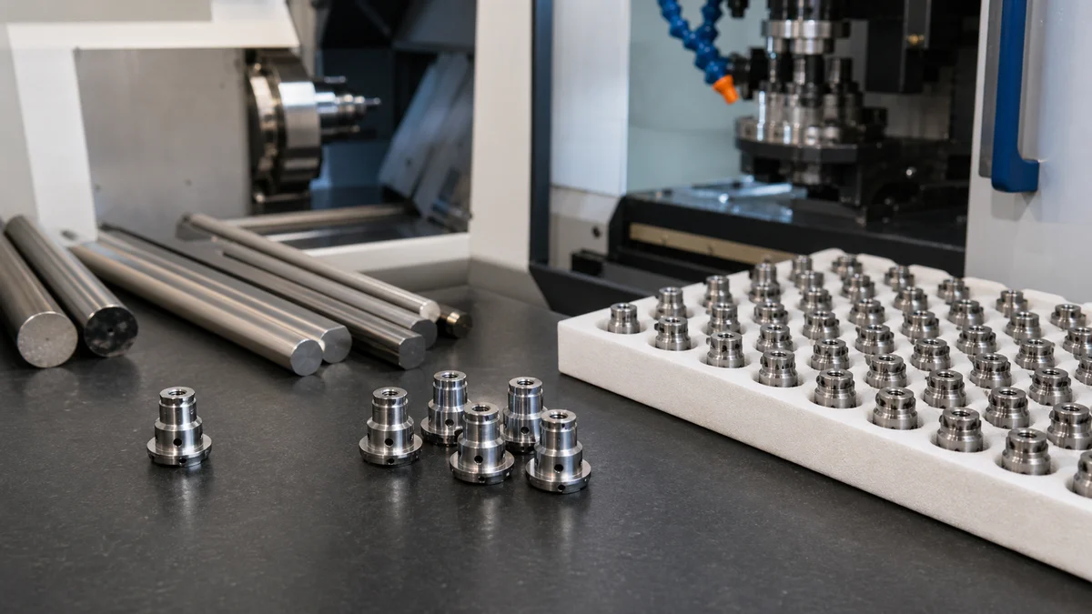
Setup economics depend on the complete manufacturing plan. Conventional turning may require less initial preparation for a short, straightforward component, especially while dimensions or features are still changing. Swiss machining can require more detailed programming and tooling preparation, yet may reduce recurring handling when several operations are completed in one cycle.
| Production condition | Primary decision risk | Route to review | Quotation input |
|---|---|---|---|
| Early prototype | Paying for a route before geometry stabilizes | Conventional turning may be simpler | Prototype quantity and expected revisions |
| Pilot batch | Proving repeatability and inspection | Compare both process plans | Pilot size and approval scope |
| Stable repeat demand | Distributing setup across recurring output | Swiss may become attractive | Annual usage and lot pattern |
| Feature-dense small part | Multiple setups and alignment transfer | Compare Swiss with turn-plus-mill | Critical feature relationships |
| Uncertain forecast | Premature process investment | Favor adaptable assumptions | Immediate quantity and forecast confidence |
Scenario: A buyer needs a design-learning batch and anticipates repeat production after assembly testing. One quantity conceals the decision. Separate prototype, pilot, and repeat-volume quotations can reveal whether conventional turning remains practical or whether Swiss setup becomes worthwhile after the design stabilizes.
Do not increase quantity merely to obtain a lower unit price while revisions remain likely. State immediate demand, expected annual usage, batch pattern, production intent, revision maturity, inspection frequency, and partial-delivery needs.
Ask suppliers for quantity-tier process quotations8 covering the complete route. Material sourcing, programming, setup, secondary operations, inspection, documentation, and delivery pattern matter more than machine rate alone. The comparison should show which assumptions change between tiers.
What Process-Selection Mistakes Should Buyers Avoid?
Avoid selecting Swiss machining merely because a part is small or selecting conventional turning without reviewing slenderness. The correct route follows workpiece support, bar compatibility, shoulders, interrupted cuts, feature access, material, tolerance, finish, quantity, revision risk, and inspection requirements.
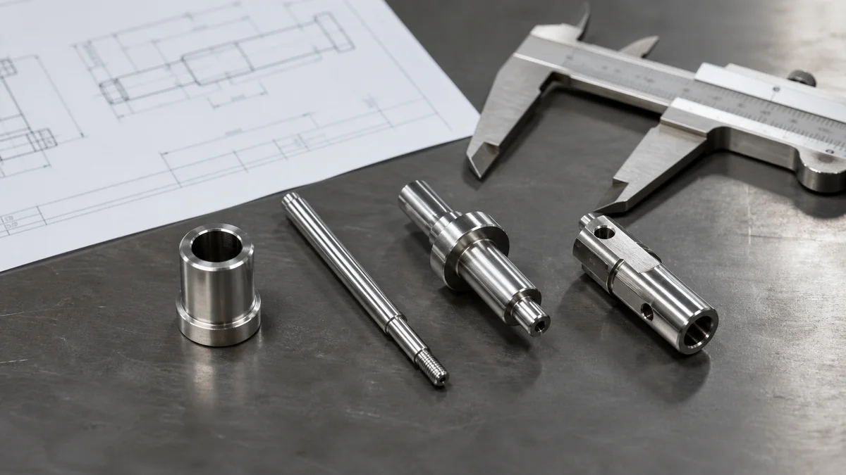
The largest mistakes occur when a process label replaces manufacturability review. Suppliers need the functional specification and enough freedom to propose a suitable route.
Avoid these assumptions:
- Every small part needs Swiss machining. A short, rigid bushing or simple threaded component may be more direct on a conventional lathe.
- Overall diameter defines stability. A large head can conceal a long reduced section carrying the real deflection risk.
- Swiss machining guarantees tolerance or finish. Material, tooling, cutting sequence, feature relationships, and inspection remain decisive.
- Every off-axis feature requires Swiss equipment. Conventional turning followed by milling may work when reclamping does not threaten function.
- Any bar can run through a guide bushing. Diameter, straightness, condition, shoulder geometry, and feeding behavior require confirmation.
- One quantity proves the best economics. Prototype and repeat-production plans can favor different routes.
Another common failure is prescribing a process while leaving controlled requirements vague. If the drawing does not distinguish critical diameters, runout, finish zones, and ordinary features, suppliers may price different interpretations. Their quotations will not represent equivalent scope.
A stronger RFQ states the required delivered condition and permits a supplier-recommended machining route9—conventional turning, Swiss machining, or combined turning and milling—when engineering allows. A mandatory process restriction should have a documented reason, such as an approved production route or a critical feature relationship.
Review the proposed stock, support method, setup count, secondary operations, inspection plan, and production intent together before approving the process.
How Should the Manufacturing Process Be Named in the RFQ?
Name the request as CNC turning or Swiss machining when rotating stock is cut to produce the part. Do not use CNC turret punching, CNC punch press, CNC-controlled stamping equipment, or metal stamping depending on the actual process as a substitute; clarify whether the intended sheet process is CNC turret punching, CNC punch press work, CNC-controlled stamping equipment, or general metal stamping.
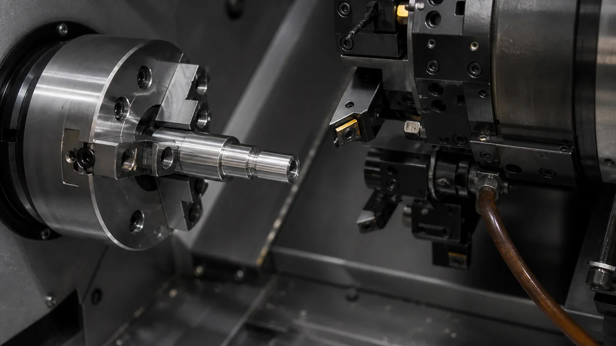
Accurate terminology prevents suppliers from quoting fundamentally different manufacturing routes. CNC turning and Swiss machining are subtractive CNC machining processes: the stock rotates while cutting tools produce diameters, faces, grooves, bores, threads, and related features.
| Process term | Material and operating principle | Relationship to this comparison |
|---|---|---|
| CNC turning | Cutting tools remove material from rotating stock | Direct comparison process |
| Swiss machining | Bar-fed turning with support close to the cut | Direct comparison process |
| CNC turret punching | Programmed punch tools shear or form sheet metal | Sheet operation, not turning |
| Metal stamping | Dedicated dies cut or form sheet or strip | Tooling-intensive sheet process |
| Sheet metal fabrication | Cutting, bending, punching, welding, and finishing may be combined | Broader sheet-based route |
| Plastic injection molding | Molten polymer fills a mold cavity | Mold-based polymer process |
The phrase CNC turret punching, CNC punch press, CNC-controlled stamping equipment, or metal stamping depending on the actual process is not a standard process term10. It may be used informally for CNC turret punching, punch press work, CNC-controlled stamping equipment, or die stamping. Replace it with the intended operation and provide the material, thickness where applicable, geometry, formed features, quantity, and production intent.
For this article's subject, the RFQ should identify a CNC-machined turned component and state whether suppliers may propose conventional turning, Swiss machining, or turn-mill processing. Flats and cross-holes do not convert turning into stamping; they may require live tooling or secondary milling, but the work remains machining from stock.
This distinction also keeps molding assumptions outside the request. Plastic injection molding forms polymer in dedicated tooling and has different material, geometry, tooling, and volume requirements.
What Should an RFQ Include for CNC Turning or Swiss Machining?
A process-selection RFQ should combine controlled design files with material, geometry, demand, tolerance, finish, inspection, revision, and delivery information. Include the dimensions that reveal slenderness and bar fit so suppliers can compare conventional turning, Swiss machining, and any acceptable combined route on consistent assumptions.
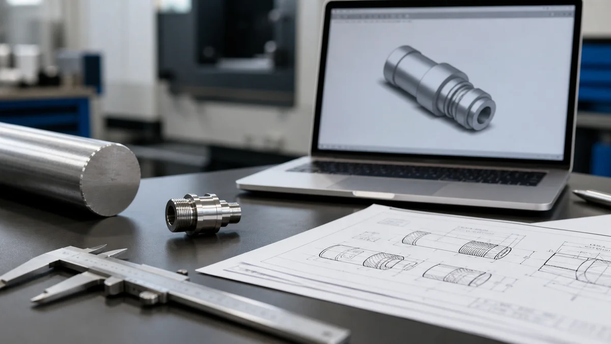
Use this CNC turning RFQ checklist11 before requesting a recommendation, sample, or quotation:
- 3D CAD model: Show the complete turned and off-axis geometry, including hidden details.
- Controlled 2D drawing: Define units, part number, active revision, threads, notes, datums, tolerances, and finish locations.
- Governing document: State which file controls if the model and drawing conflict.
- Exact material: Give the grade, temper, hardness or condition, and stock form. List alternatives only when engineering permits them.
- Diameter data: Include maximum and minimum diameters, shoulder sizes, and every reduced section.
- Slenderness data: Identify overall length and the longest unsupported section at its relevant diameter.
- Complete feature set: Mark cross-holes, flats, slots, grooves, threads, undercuts, and second-end features.
- Functional relationships: Define runout, coaxiality, position, face-to-diameter, and other assembly controls with appropriate datums.
- Tolerance plan: Separate functional and assembly features from cosmetic and non-critical dimensions.
- Surface requirements: Localize roughness and cosmetic zones; identify permitted secondary finishes and whether dimensions apply before or after treatment.
- Inspection scope: State first-article, sampling, final-report, or selected-feature requirements and any relevant measurement condition.
- Demand: Provide immediate quantity, prototype or production intent, annual usage if known, batch pattern, and revision stability.
- Delivery expectations: Include the requested schedule, partial-shipment needs, and approval sequence.
- Process flexibility: State whether conventional turning, Swiss machining, or turn-mill alternatives may be quoted.
Complete inputs let suppliers compare support strategy, bar use, tooling, setup count, secondary operations, inspection effort, cost, and schedule. They also make competing quotations comparable because every supplier is pricing the same delivered requirement.
Send the 3D model, controlled 2D drawing, material grade and condition, quantity, critical tolerances, surface finish, inspection expectations, revision level, delivery needs, and prototype or production intent. Include maximum and minimum diameters plus unsupported lengths so the supplier can recommend and quote the appropriate turning route.
References
-
Swiss Machining Design Guide: Is It Right for Your Parts? - Swiss machining's guide bushing system provides superior support for the workpiece, enabling tighter tolerances (typically ±0.0005′′ vs. ±0.001′′ for ... ↩
-
Deflection and Precision in Swiss Metal CNC Machining - Where the length-to-diameter ratio is greater than 6:1, you should support the middle of the parts using a steady rest or follow rest. The ... ↩
-
Swiss machining: technology, applications, and economics - Swiss machining is a specialized form of CNC turning with a sliding headstock and guide bushing. a guide bushing supporting the bar immediately ... ↩
-
CNC Machining | raw stock for a swiss style turning center - The most important thing since the guide bushing adjustment is fixed is that the barstock has no or minimum (a few .0001s) taper. Roundness ... ↩
-
CNC Swiss Turning: What It Is, How It Works, and When ... - A sub-spindle picks off the part from the main spindle, performs back-working and parts it off synchronously. Live tooling on multiple axes ... ↩
-
Dimensional Inspection Planning Methodologies - Dimensional inspection planning is an activity to generate specific inspection instructions to inspect manufactured parts based on the product design. ↩
-
Surface Roughness Symbols: Drawing Examples & ISO ... - Learn how to read surface roughness symbols on engineering drawings, understand ISO 1302 standards, surface finish callouts, and Ra values. ↩
-
Process Planning for Small Batch Manufacturing - Sites at USC - This will help in reducing the setup times and setup costs for the small batch manufacturing environment. For the example of ten parts, a single-part planning ... ↩
-
What Is Design for Manufacturing (DFM)? Principles, ... - Early DFM includes process screening: machining vs. casting vs. forging vs. molding vs. sheet metal—based on volume, tolerances, and constraints. ↩
-
CNC Turret Punch Guide: Process, DFM, Cost vs Laser - CNC turret punching is a sheet metal fabrication process that produces holes, slots, cutouts, and formed features in flat sheet using a CNC- ... ↩
-
CNC Machining RFQ Checklist: Get Faster, Accurate Quotes - 1) Send both the drawing and the 3D model (when available) · 2) Confirm material, temper, and any compliance requirements · 3) Define quantity and ... ↩