
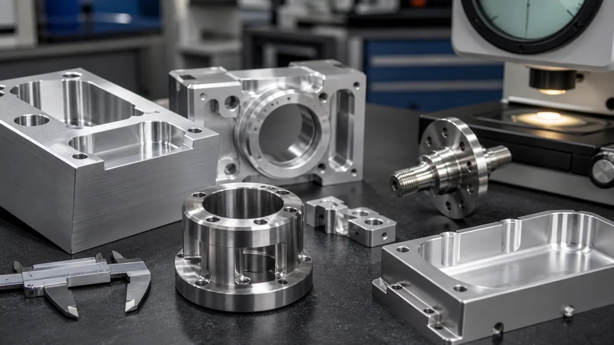
Burrs and edge breaks may look like minor finishing details, but they can change how a CNC machined part handles, seals, locates, fits, and accepts a coating. A note such as “deburr and break all sharp edges” often leaves the supplier to decide which edges it covers and how much material may be removed.
A useful specification separates unwanted burrs from intentional edge geometry. It classifies edges by function, protects critical sharp features, selects deburring methods that fit the material and geometry, and defines how the finished condition will be inspected.
These decisions turn edge control from a subjective workmanship request into a clear machining, drawing, inspection, and RFQ requirement.
What Is the Difference Between Burr Removal and an Edge Break?
A burr is unwanted material projecting from an edge, while an edge break is intentional material removal that creates a chamfer, radius, or controlled undefined edge. Specify them separately because a part can be burr-free while retaining a functionally sharp edge.
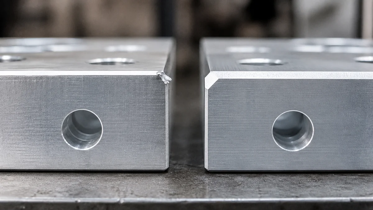
Burr removal addresses material that the manufacturing process was not intended to leave. Burrs can form where a cutter exits a surface, a drill breaks through a wall, or two machined features intersect. Their direction and accessibility may matter as much as their apparent size, particularly near mating parts, seals, or internal passages.
An edge break changes the intended geometry. It may be a dimensioned chamfer, a radius, or a controlled edge whose exact final profile is not functionally important. Removing a burr should not automatically authorize the supplier to round or chamfer the underlying intersection.
| Requirement | Controlled condition | Drawing instruction |
|---|---|---|
| Burr removal | Unwanted projecting material | State the permitted edge condition or burr limit where relevant |
| Chamfer | Flat, angled edge geometry | Dimension the width and angle directly |
| Radius | Rounded edge geometry | Dimension the radius directly |
| Preserved sharp edge | Functional intersection with minimal alteration | Mark it as protected or excluded from the general note |
Example: A machined plate may need burr-free handling edges while retaining a sharp locating edge against an assembly stop. A broad edge-break instruction could shorten the locating surface, change the contact line, and affect how the plate seats.
A sound drawing therefore answers two independent questions: what unwanted material must be removed, and what intentional geometry may replace the nominal intersection? This distinction between a burr and an edge break1 lets the supplier plan machining and cleanup without interpreting “deburr” as permission to round every edge.
How Should Edge Function Determine the Callout?
Classify each edge by what it must do before choosing its callout. Handling, sealing, routing, locating, cutting, coating, and mating edges can require different conditions, so one general edge-break note should cover only edges with comparable functional risk.
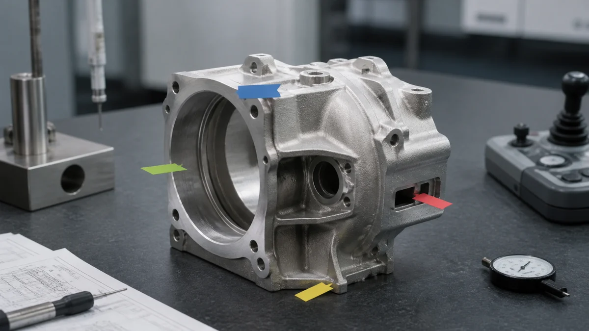
Begin by dividing the part into functional, assembly-related, cosmetic, and ordinary edges. This keeps a safety-oriented handling requirement from controlling a sealing land, cutting feature, or reference edge that serves a different purpose.
- Handling edges: Remove hazardous projections and define a non-sharp condition suitable for normal handling.
- Seal-protection edges: Control the entry geometry so it does not cut or damage a seal during installation.
- Wire-routing edges: Prevent abrasion where cables, hoses, or insulation cross the part.
- Mating and clearance edges: Limit the edge condition so it does not interfere with an adjacent component.
- Locating or reference edges: Preserve the intended contact line or control it with a separate callout.
- Cutting or metering edges: Retain sharpness when the edge itself performs the function.
- Cosmetic edges: Coordinate edge appearance with the visible surface finish.
Geometry and material refine this classification. A thin wall may not tolerate the same edge-removal method as a thick flange. A small hole opening into a passage may need internal burr control rather than an external handling chamfer. Coating or plating can also change the final transition, so state whether acceptance applies before or after finishing when buildup could affect fit or appearance.
Scenario: A housing has external handling edges, a seal entry, and a sharp metering feature. The external edges can share a general note. The seal entry needs defined geometry, while the metering edge needs an explicit exclusion. This edge classification by function2 prevents the three requirements from conflicting.
When Should You Use ISO 13715 or a Defined Chamfer or Radius?
Use ISO 13715 when an edge of undefined final shape needs standardized drawing control. Dimension a chamfer or radius directly when its geometry affects fit, sealing, assembly, safety, or another function. Always state the governing standard and identify exceptions.
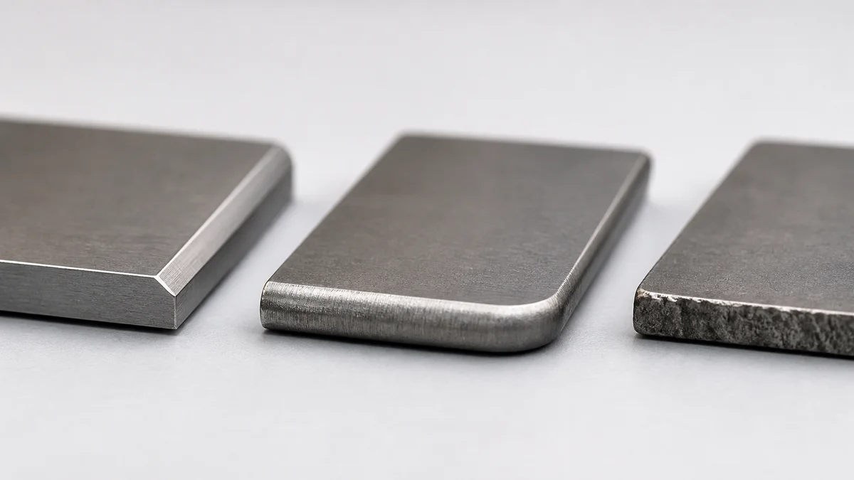
ISO 13715 provides drawing language for edges whose exact final shape is not otherwise defined. It can suit an edge where the permitted departure from the ideal intersection matters, but a precise chamfer profile or radius does not.
Choose a defined chamfer or radius when the geometry itself performs a job. Typical purposes include guiding a seal, clearing a mating corner, protecting a cable, controlling contact, or producing a consistent visible transition. The drawing should communicate that geometry directly instead of expecting a general deburring note to create it.
| Specification situation | Preferred drawing control | Practical consequence |
|---|---|---|
| Exact edge profile is not functionally important | ISO 13715 indication, where applicable | Controls the permitted undefined edge condition |
| Flat angled transition is required | Direct chamfer dimension | Defines the intended width and angle |
| Rounded transition is required | Direct radius dimension | Defines the functional curved geometry |
| Edge must remain sharp | Protected-edge note or local callout | Prevents unintended material removal |
| Most edges share one condition but several do not | General note with local exceptions | Keeps the drawing concise without hiding critical differences |
A common mistake is to reference a standard and add “break all edges” without stating which instruction governs. Another is to model a chamfer in the 3D file but omit its controlled dimension from the 2D drawing.
The drawing should identify the applicable revision of the governing edge standard3, the general edge condition, locally defined geometry, and exclusions. If the model and drawing disagree, the RFQ must name the controlling document before quotation and inspection.
How Can the Machining Plan Reduce Burr Formation?
Reduce burrs during machining by reviewing material behavior, tool condition, feed direction, feature exits, hole breakthrough, support, and operation sequence. Preventing a large or inaccessible burr is generally more controllable than relying on aggressive cleanup after machining.
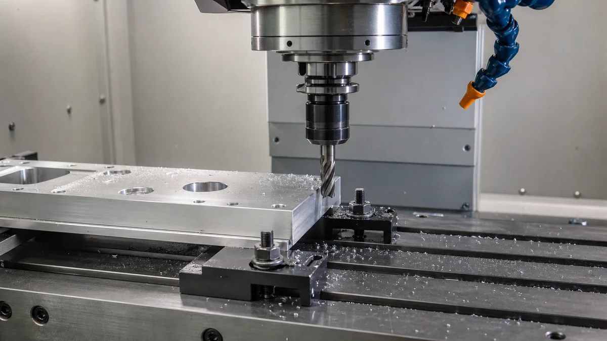
Burr location is often related to how the cutting edge leaves the material. An external profile may develop a burr on the cutter-exit side, while a drilled hole may leave material at breakthrough. Intersecting passages can create internal burrs that are difficult to reach without changing the bore or surrounding surface.
The supplier should have room to plan cutting direction, toolpath, support, and operation sequence around these risks. The buyer normally does not need to prescribe feeds, speeds, or a particular cutter. The RFQ should instead identify features where burr direction, access, or residual material affects flow, fit, sealing, safety, or cleanliness.
Which geometry deserves early review?
Thin walls can deflect as a cutter exits, producing an uneven edge and making later hand cleanup risky. Small openings and deep passages restrict tool access. Hole intersections may trap chips or leave projections inside a flow path. Cosmetic faces can be marked if a cleanup tool contacts more than the edge itself.
Material grade and condition also influence how chips form and release. Tool condition can affect both burr formation and surface finish, so repeat-production planning should address stable edge results rather than evaluate only the first acceptable part.
Example: Two drilled passages intersect inside a manifold. “Deburr all holes” does not say whether internal projections are allowed or how passage clearance will be verified. Marking the crossing as functionally critical lets the supplier plan the drilling sequence, burr direction, access, and inspection before cutting begins.
This prevention-first machining strategy4 reduces dependence on aggressive secondary cleanup, but it does not replace a defined final acceptance condition.
Which Deburring Method Fits the Material and Part Geometry?
Choose deburring by matching the method to the material, edge access, wall thickness, holes, threads, surface finish, cleanliness, quantity, and production intent. Restrict methods where dimensional change, surface alteration, trapped media, or loss of critical edge geometry would be unacceptable.
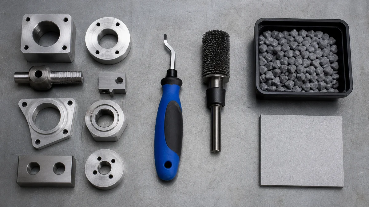
No deburring method suits every part. Manual tools can target a local feature but may introduce operator-dependent variation. Brushing may work on accessible edges yet contact nearby surfaces. Tumbling treats many exposed edges together, but it can round features broadly, create part-to-part contact, or leave media in cavities. Blasting changes surface texture as well as edge appearance.
Thermal and electrochemical methods remove burrs through different mechanisms and may fit difficult-to-reach geometry after supplier review. Their compatibility with the material grade, threads, internal passages, finish, and dimensional requirements cannot be assumed from the method name alone.
| Method family | Potential application | Specification risk to review |
|---|---|---|
| Hand tools | Local, accessible edges or limited quantities | Variable edge size and accidental surface damage |
| Brushing | External edges and accessible hole entries | Contact with adjacent finish or delicate geometry |
| Tumbling | Multiple exposed, noncritical edges | Broad rounding, part contact, and retained media |
| Blasting | Cleanup coordinated with surface treatment | Altered cosmetic texture and exposure of protected areas |
| Thermal or electrochemical | Suitable inaccessible burrs after process review | Material compatibility, dimensional effects, and critical edges |
Quantity and production intent affect process fit. A prototype may reasonably use localized manual work, while repeat production may need a more stable deburring process5 and an agreed sampling plan.
The RFQ should identify prohibited media, cleanliness requirements, no-contact cosmetic zones, protected threads, thin walls, and sharp functional edges. Let the supplier recommend the method, but require approval if it could change controlled geometry, tolerance, or surface finish.
Which Critical Edges Must Be Excluded from Blanket Edge-Break Notes?
Exclude any edge whose sharpness, contact line, opening, or transition controls function. Seal lands, locating edges, valve seats, press-fit shoulders, metering orifices, cutting features, and sharp reference edges should remain protected or receive a separate measurable callout.
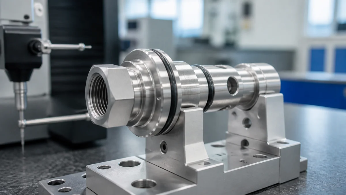
A blanket note is useful only when all covered edges have comparable requirements. It becomes risky when applied to features whose performance depends on preserving the nominal intersection or tightly limiting material removal.
Review these edge groups before releasing the drawing:
- Seal lands and valve seats: Uncontrolled rounding can reduce contact area or change engagement with the mating element.
- Locating and reference edges: Material removal can shift the effective contact point used for assembly or inspection.
- Press-fit shoulders: A broad edge break may reduce seating area or alter the transition beside the fitted feature.
- Metering orifices and flow features: Edge shape can change the effective opening, making vague deburring language inadequate.
- Cutting and scraping features: The edge may need to remain functionally sharp rather than simply burr-free.
- Thin-wall intersections: Manual cleanup can deform the wall or produce an uneven transition.
- Cosmetic transitions: Inconsistent finishing may remain visible after blasting, anodizing, plating, or polishing.
The controlled 2D drawing should show these exceptions because a 3D model normally represents ideal geometry, not the permitted residual burr or final edge condition. Detail views can identify small or hidden features that would be ambiguous in the main view.
A common blanket edge-break mistake6 is showing a nominally sharp seal land while stating “break all sharp edges.” The supplier cannot know whether the general note overrides the model. Exclude the seal land explicitly and define its permitted condition locally.
When several critical edges share one rule, use a numbered edge map to keep each location traceable through machining and inspection.
How Should Burrs and Edge Breaks Be Inspected and Accepted?
Match inspection to edge function and acceptance risk. Ordinary handling edges may use visual examination, while critical edges may require measured chamfer width, radius, burr height, magnification, comparator evaluation, or an approved limit sample with defined inspection frequency.
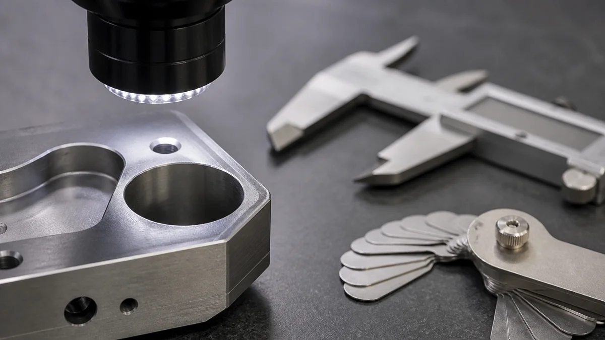
Inspection should verify the requirement placed on the drawing. A visual check may confirm that an accessible handling edge has no obvious hazardous projection, but it cannot establish a dimensioned chamfer or quantify a functional burr limit.
| Edge requirement | Inspection approach | Acceptance information to define |
|---|---|---|
| Ordinary burr-free handling edge | Visual examination | Accessible surfaces, viewing condition, and workmanship expectation |
| Defined chamfer | Dimensional or comparator check | Width, angle, tolerance, and sampling scope |
| Defined radius | Suitable radius or profile evaluation | Radius, location, tolerance, and measurement method |
| Controlled burr height | Measurement or magnified examination | Permitted limit, direction, location, and reporting need |
| Cosmetic edge | Approved visual standard or limit sample | Viewing condition, cosmetic zone, and sample control |
| Internal or restricted edge | Access-appropriate inspection | Critical location, passage clearance, and required evidence |
Inspection frequency should follow feature risk and production intent. The RFQ may require first-article results for critical edges, sampling during repeat production, or documented checks on selected features. Requiring the same method for every edge usually adds work without improving acceptance.
An approved limit sample can help when appearance or tactile condition cannot be communicated adequately with words. Identify and control the sample so buyer and supplier compare parts against the same reference.
Avoid “smooth,” “lightly deburred,” or “no sharp edges” when disagreement could affect acceptance. These phrases do not establish size, burr direction, inspection method, or whether a functionally sharp edge is permitted. A risk-based edge inspection plan7 makes those decisions explicit before production.
What Edge-Control Information Belongs in a CNC Machining RFQ?
A complete edge-control RFQ should identify the process, model and drawing revisions, material, quantity, production intent, edge standard, general condition, local exceptions, defined geometry, burr limits, finish, cleanliness, inspection evidence, and delivery expectations. It should also resolve any ambiguous process terminology.
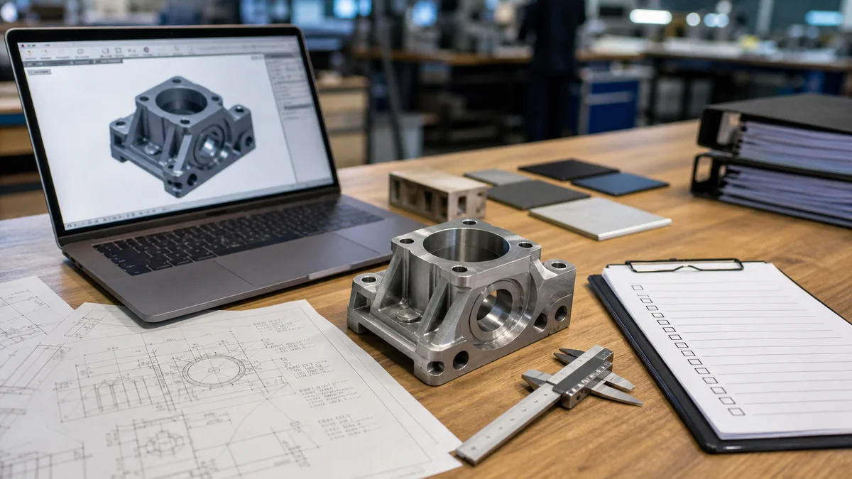
Send enough information for the supplier to plan machining, deburring, finishing, and inspection as one coordinated route. The 3D model communicates the complete geometry, while the controlled 2D drawing governs edge notes, dimensions, exceptions, and acceptance. State which document controls if they conflict.
Edge-control RFQ and approval checklist
- ☐ Current 3D CAD model and controlled 2D drawing
- ☐ Part number, units, drawing number, and active revision
- ☐ Exact material grade and condition
- ☐ Immediate quantity and expected repeat demand, if known
- ☐ Prototype, validation, pilot, or repeat-production intent
- ☐ Governing drawing and edge standard, including revision where applicable
- ☐ General burr and edge condition for ordinary features
- ☐ Defined chamfers and radii on functional edges
- ☐ Protected sharp edges and explicit exclusions from blanket notes
- ☐ Allowed burr direction or limit where function makes it relevant
- ☐ Internal intersections, small openings, thin walls, and restricted access
- ☐ Prohibited deburring methods or protected surfaces
- ☐ Surface finish, coating, masking, cleanliness, and cosmetic zones
- ☐ Whether critical acceptance applies before or after finishing
- ☐ Inspection method, first-article scope, sampling, reports, or limit samples
- ☐ Delivery expectations and approval timing
Use correct manufacturing process terminology8. CNC machining removes material from solid stock through milling, turning, drilling, boring, and reaming. CNC turret punching or a CNC punch press uses programmed punch tooling on sheet metal. Metal stamping uses dies to cut or form sheet and may involve springback and burr-direction decisions. Sheet metal fabrication can combine cutting, punching, bending, welding, and finishing. Plastic injection molding forms polymer in a mold, where draft and gate location are molding considerations rather than CNC edge-break specifications.
“CNC turret punching, CNC punch press, CNC-controlled stamping equipment, or metal stamping depending on the actual process” is not one standard process term. Clarify whether it means CNC turret punching, a CNC punch press, CNC-controlled stamping equipment, or general metal stamping before comparing edge quality, tooling, or inspection.
For a deburring recommendation or quotation, send the current 3D model, controlled 2D drawing, material grade, quantity, prototype or production intent, critical tolerances, protected edges, surface finish, inspection expectations, revision level, and delivery requirements. Identify any allowed burr direction, burr limit, or restricted deburring method.
References
-
ISO 13715:2000(en), Technical drawings - This International Standard defines the terms defining the states of edges and specifies rules for representing states of edges of undefined shape in technical ... ↩
-
Edge Protection - Flexiform grommet strips are used to protect cables and wires routed through sharp-edged cutout sections. They can be applied without adhesive ↩
-
ISO 13715:2017 - Edges of undefined shape - ISO 13715:2017 specifies rules for the indication and dimensioning of undefined edges in technical product and dimensions. ↩
-
Investigation on the Exit Burr Formation in Micro Milling - PMC - by Z Chen · 2021 · Cited by 23 — In this paper, the formation mechanism of exit burr was studied based on the varying cutting direction during micro milling. Three exit burr ... ↩
-
Deburring Processes and Challenges - SME.org - Choices range from special rotary chamfering tools to electrochemical, thermal, brush, and other methods. The key to brush deburring is ... ↩
-
Deburr & Edge Break Callouts: Avoid Sharp Edges Without ... - The drawing includes one note: “Break all sharp edges.” Forgetting Functional Sharp Edges Some edges need to remain crisp. A sealing edge, ... ↩
-
Optical Comparators: Applications and Uses - Optical comparators provide manual, visual measurement of two-dimensional parts, relying on operator skill and magnified image overlays. They ... ↩
-
Stamping Metal / Punching Metal Service USA. Get Price! - Sheet metal punching in metal fabrication is the process of using a machine to press a shape through a sheet of metal and into a die to create the desired shape ... ↩