
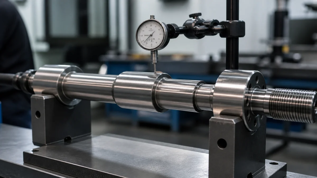
Concentricity and runout problems on CNC turned parts often start with an unclear functional axis, an avoidable setup transfer, or an inspection method that does not match the drawing. A tight numerical callout alone cannot keep bearing journals, sealing diameters, bores, and rotating interfaces aligned.
Effective control begins with choosing the geometric requirement that represents the part’s function. The machining plan must then support it through datum selection, setup sequence, workholding, material stability, tool control, and inspection in the agreed delivered condition.
The decisions below connect rotating-part function to practical drawing callouts, machining setups, production controls, inspection evidence, and a quotation-ready RFQ.
Should You Specify Concentricity, Circular Runout, or Total Runout?
Choose the control that represents the part’s actual rotating function. Circular runout controls variation at individual cross-sections, total runout controls variation across an entire surface, and concentricity evaluates derived median points relative to a datum axis. These requirements are related but not interchangeable.
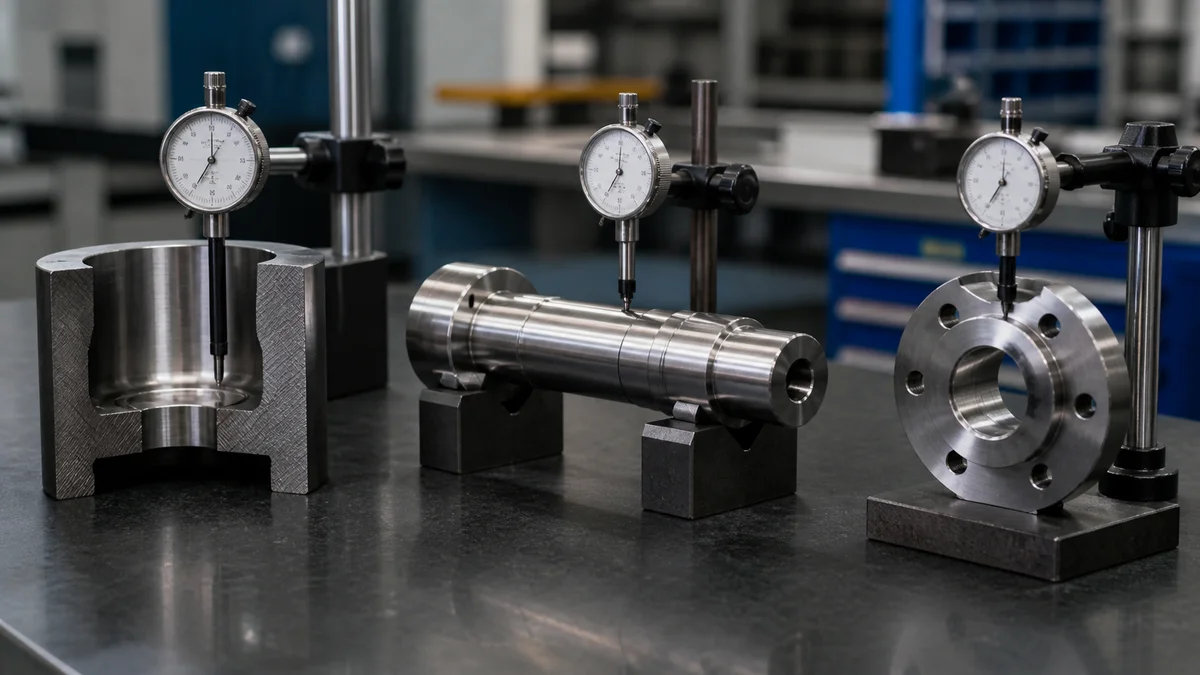
Concentricity is not a general label for a precise cylindrical part. It evaluates how a feature’s derived median points relate to a datum axis, so verifying it can require more than sweeping an indicator across the surface. Reserve it for a genuine requirement involving material distribution around that axis.
Circular runout evaluates surface variation at each measured circular element as the part rotates about its datum axis. It is often a direct control for a bearing journal, sealing land, or another rotating surface at a specified section. Total runout applies across the full controlled surface and captures variation along its length.
| Drawing control | Evaluated characteristic | Appropriate specification question |
|---|---|---|
| Concentricity | Derived median points relative to a datum axis | Must the feature’s material distribution remain centered? |
| Circular runout | Surface variation at individual cross-sections | Must this section rotate consistently about the datum? |
| Total runout | Surface variation over the controlled length | Must the complete journal or face remain consistent during rotation? |
| TIR reading | Total indicator movement in a stated setup | What variation was observed during this particular check? |
A TIR reading is a measurement result, not automatically a complete geometric specification. The drawing still needs the datum feature, controlled surface, tolerance, and applicable characteristic. Referencing a recognized geometric dimensioning and tolerancing standard1 also establishes how the symbols and datum framework are interpreted.
Specification mistake: Calling out concentricity on every diameter when the functional concern is bearing rotation adds interpretation and inspection effort. If the surface itself governs acceptance, circular or total runout usually communicates the requirement more directly.
Which Coaxial Diameters Should Be Finished in One Setup?
Finish bearing journals, sealing diameters, locating bores, and other functionally coaxial surfaces in one chucking whenever geometry and tool access permit. Maintaining one spindle axis reduces error associated with chuck seating, reclamping, datum transfer, and movement between separate machining operations.
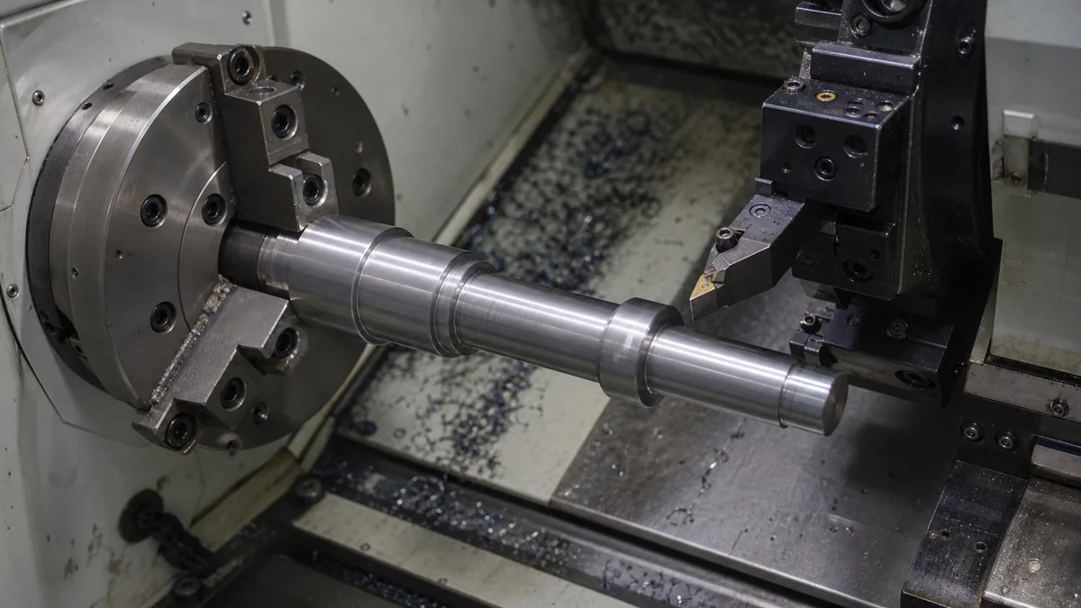
Group turned features by how the assembled component rotates, locates, seals, or carries load. Diameters sharing a bearing axis, seal axis, or mating-bore relationship normally deserve priority for single-setup finishing. Clearance diameters, reliefs, and cosmetic surfaces do not automatically belong in that group.
A sound sequence is to rough the related geometry, account for likely material movement, and finish the critical surfaces before releasing the primary workholding. This preserves a common spindle reference and avoids adding reclamping error2 to the functional relationship. Feasibility still depends on tool access, shoulders, stock allowance, part length, wall thickness, surface finish, and second-end geometry.
Must every coaxial feature be completed before transfer?
No. A shoulder may block the tool, a reverse-end face may remain inaccessible, or off-axis details may require a secondary operation. The drawing should identify which relationships remain critical across setups instead of forcing every feature into one machining sequence.
Example: A stepped shaft has two bearing journals separated by a shoulder and a non-contact relief diameter. If both journals govern rotation, finishing them in one chucking protects their shared axis. The relief can remain under an appropriate general tolerance because it neither locates nor contacts the mating assembly.
Do not mandate one setup when stable support or safe cutter access makes it impractical. Mark the functional diameter group, the required surface-finish zones, and any allowable secondary operations. The supplier can then compare conventional turning, turn-mill machining, center support, or controlled part transfer without guessing which relationships matter.
How Should a Second Setup Reference the Functional Axis?
When a part must be flipped or transferred, relocate it from a feature representing the same functional axis established in the first setup. Define that datum on the drawing, identify critical cross-setup relationships, and require the proposed workholding and verification method to follow it.
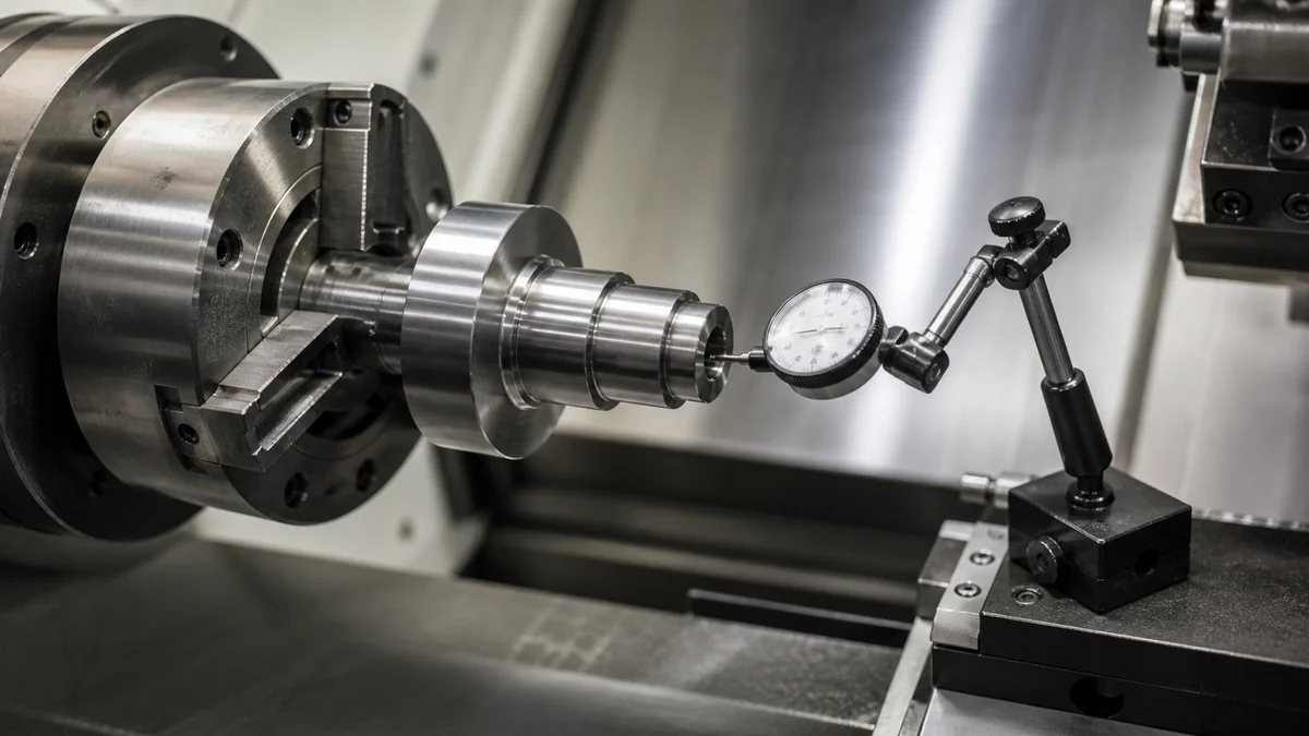
A second setup should preserve datum continuity3 instead of locating from whichever surface is easiest to grip. The locating feature needs to be stable, accessible, repeatable, and representative of the part’s assembled rotation. It may be a finished outside diameter, a controlled bore, center features, or another cylindrical datum feature.
Possible relocation methods include:
- Use a collet for distributed contact on a suitable finished outside diameter.
- Bore soft jaws in place to match a stable gripping diameter and axial stop.
- Locate on a precision mandrel when a controlled bore establishes the functional axis.
- Use centers when the shaft geometry includes suitable center features and needs additional support.
- Combine a repeatable locating bore with an axial stop when both axis and length must be re-established.
Each method has limits. A collet may distort a thin wall. Soft jaws depend on clean seating, adequate grip length, and consistent axial contact. A mandrel transfers locating error through the bore, so that bore must be appropriate as a datum. Centers need compatible end geometry and sufficient stiffness.
The drawing should control second-end features relative to the same functional axis and distinguish size requirements from runout. It should also state whether dimensions and surface finish apply before or after heat treatment, plating, anodizing, or another secondary process that could affect the finished relationship.
Ask how the datum will be re-established, where the fixture contacts the part, which surfaces may receive grip marks, and how seating will be verified. Final inspection should reproduce this datum logic; otherwise, machining and inspection may evaluate different axes.
How Should Workholding Change for Thin-Wall or Slender Turned Parts?
Use workholding that distributes gripping force and supports compliant geometry without crushing, bending, or pulling it off-axis. Material condition, wall thickness, unsupported length, grip area, cutting force, and the part’s shape after unclamping should determine the holding and support strategy.
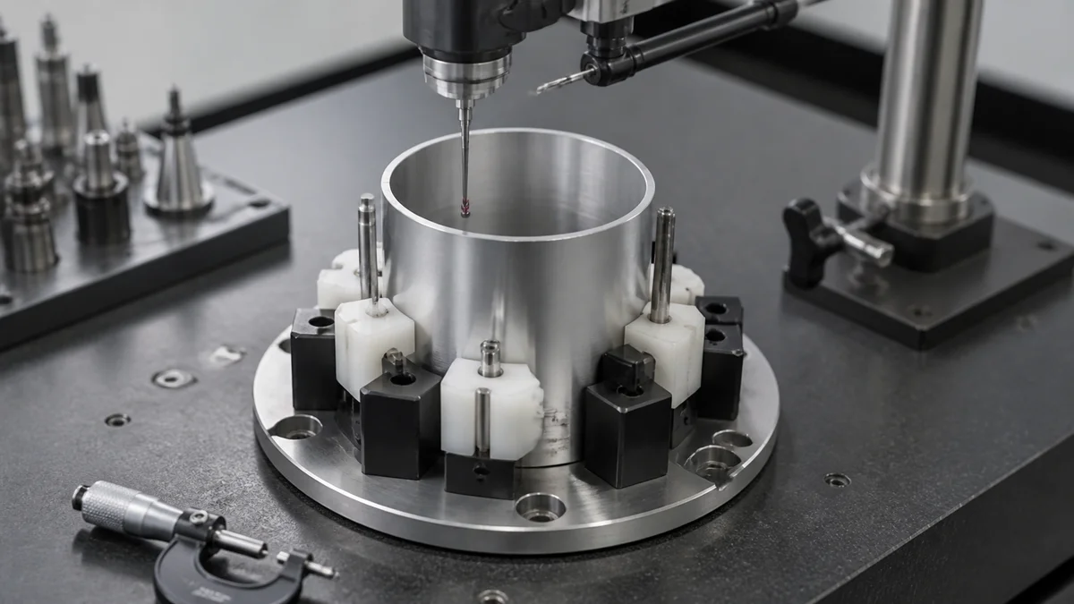
A compliant part can indicate acceptably while clamped yet show runout after release because the fixture temporarily forces it into shape. Thin sleeves, long shafts, narrow journals, soft materials, and interrupted walls are particularly sensitive. Unless the assembly requires another agreed condition, acceptance should represent the delivered part after it is unclamped.
| Part condition | Workholding response to evaluate | RFQ detail that affects the decision |
|---|---|---|
| Thin cylindrical wall | Distributed external grip or internal support | Minimum wall thickness, grip length, and no-clamp zones |
| Long slender shaft | Center, steady, or another suitable support | Longest unsupported span and critical journal locations |
| Compliant datum bore | Controlled mandrel or supported-bore strategy | Bore datum, wall condition, and allowable contact area |
| Soft or easily marked material | Limited, evenly distributed gripping force | Exact material grade, condition, and cosmetic restrictions |
| Finished outside diameter | Protected contact or alternate grip surface | Surface finish, allowed witness marks, and datum priority |
Workholding cannot be separated from cutting strategy. Short tool overhang, balanced stock removal, controlled engagement, and light finishing passes may reduce deflection. The RFQ should define the required geometry and finish while leaving unsupported feeds, speeds, and clamping pressures to the supplier’s process plan.
Scenario: A thin aluminum sleeve is gripped heavily on its outside diameter, bored, and inspected while held. The bore appears aligned, but the sleeve springs back after release and its measured runout changes. This teaching scenario shows why wall thickness, material temper, grip restrictions, datum axis, and free-state inspection4 belong in the specification.
Where distortion is credible, ask how the supplier will separate machining error from elastic deformation and how the inspection support will avoid bending the part again.
What Machine and Workholding Checks Support Repeatable Runout?
Verify the complete rotating and locating system before finishing critical surfaces. The supplier’s plan should address spindle condition, chuck or collet behavior, fixture seating, tool condition, stable cutting parameters, warm-up, and thermal stabilization for the specified geometry, material, quantity, and tolerance.
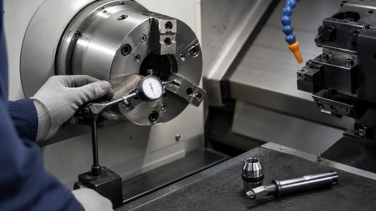
The finished part reflects the whole machining system, not the nominal condition of one component. Contamination on a locating surface, damaged jaws, inconsistent collet seating, a worn cutting edge, unstable temperature, or changing chip behavior can shift the axis seen by the tool.
Before critical finishing, the setup review should address:
- Clean and examine datum contacts, jaws, collets, mandrels, centers, and axial stops.
- Verify the indicated behavior of the spindle and gripping arrangement in the planned configuration.
- Confirm seating repeatability after loading and after representative reclamping when a second setup is required.
- Check tool edge condition, overhang, insert indexing, and the verification required after tool replacement.
- Use a suitable spindle warm-up5 and thermal stabilization approach for the material, cycle, geometry, and tolerance.
- Maintain chip evacuation so debris cannot collect between the part and a locating surface.
- Recheck the setup after adjustments that can alter the datum axis or finished diameter.
These are process-control questions, not reasons to prescribe a machine brand or claim a universal capability. Identical workholding can behave differently with a short steel shaft, a thin aluminum sleeve, and a long engineering-plastic component.
Ask the supplier for a part-specific description of setup verification: what is checked before cutting, which events trigger another check, and how suspect setups are handled. When several tools finish related surfaces, the plan should identify the feature that establishes the datum and the surfaces that depend on it.
Warm-up alone cannot control runout. Repeatability comes from thermal stability working together with clean seating, suitable support, tool-wear control, and inspection tied to the drawing.
How Should Runout and Concentricity Be Inspected from the Datum Axis?
Inspect from the drawing’s datum axis and reproduce functional rotation as closely as practical. Define the geometric characteristic, controlled surfaces, measurement locations, cleanliness, support, sampling, reporting, and delivered condition. Indicator-based checks may suit accessible runout, while concentricity can require more structured evaluation.
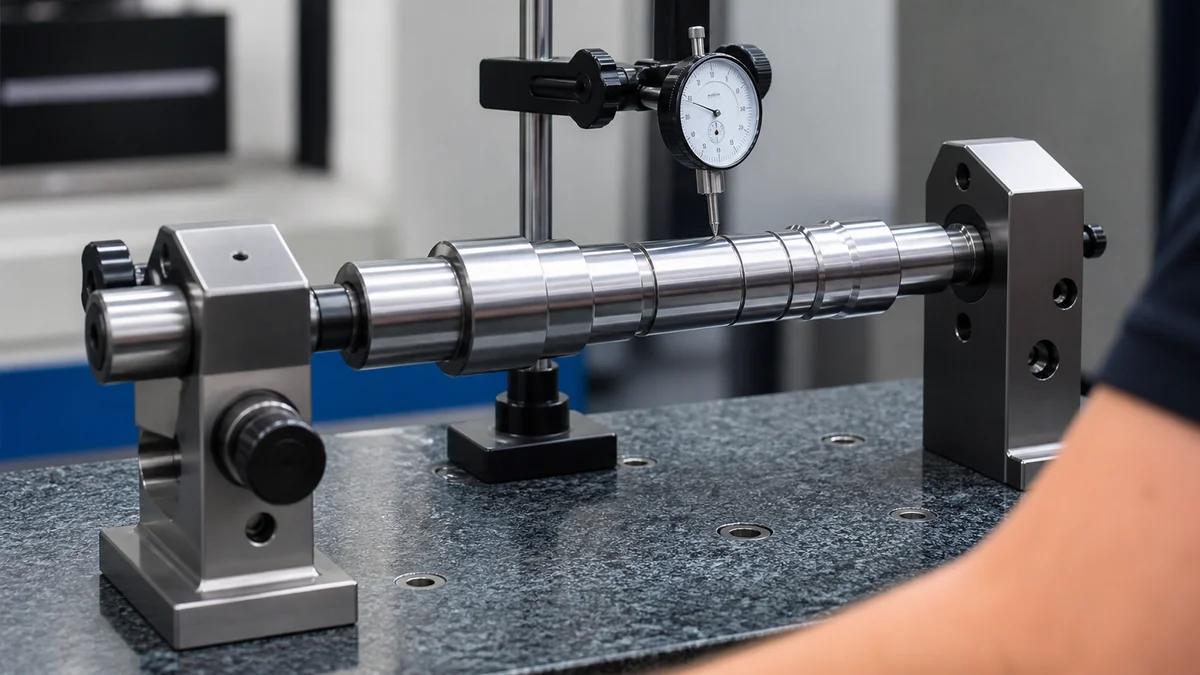
Inspection must establish the specified datum feature before evaluating the controlled surface. Mounting a component between convenient centers or gripping an unrelated diameter may give a repeatable reading, but it does not verify the drawing requirement. Contacts and surfaces must be clean, consistently seated, and supported without meaningful distortion.
| Inspection specification | Information to state | Consequence if omitted |
|---|---|---|
| Reported characteristic | Circular runout, total runout, concentricity, or a defined TIR reading | Different evaluation methods may be used |
| Datum basis | Datum feature and resulting datum axis | The part may be rotated about the wrong axis |
| Measurement location | Named diameter, face, section, or full controlled length | Local variation may be missed or measured elsewhere |
| Part condition | Free, supported, coated, heat-treated, or otherwise finished | Results may change with restraint or processing stage |
| Inspection frequency | First article, sampling, periodic, or selected 100 percent inspection | Suppliers must estimate unpriced metrology effort |
| Required evidence | Recorded values, dimensional report, or approval status | Acceptance records may not meet buyer needs |
A dial indicator can suit accessible runout measurements6 when the fixture accurately establishes the datum axis. Concentricity evaluates derived median points and should not automatically be reduced to an indicator sweep. A complex datum system or inaccessible feature may require a more structured measurement method.
Is a TIR limit enough for acceptance?
Only when the datum, mounting arrangement, controlled surface, indicator position, and rotation method are defined. Otherwise, two valid-looking setups can produce different results.
Measurement force and support are especially important for slender shafts and thin walls. The inspection method must not recreate clamping distortion or bend the component. Agree on the measurement condition before quotation when the result controls acceptance.
How Should Runout Drift Be Controlled During Production?
Control production drift with checks tied to known change points, not first-article approval alone. The plan should address tool wear, tool replacement, temperature, chips, workholding variation, inspection frequency, offset authority, stop criteria, and containment of parts produced since the last accepted result.
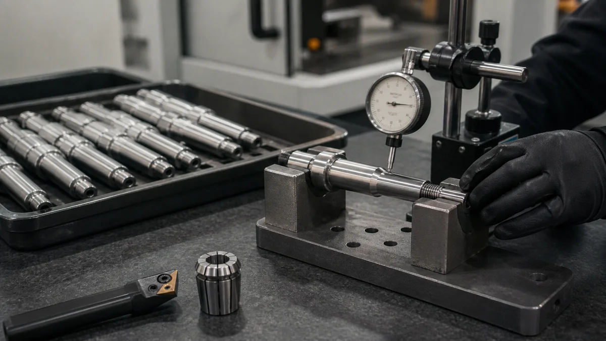
A conforming first piece demonstrates one result under one set of process conditions. It does not control what happens as cutting edges wear, temperature changes, chips interfere with seating, or workholding components accumulate contamination. Inspection frequency and reaction rules should reflect quantity, feature risk, material, geometry, and production intent.
A practical control plan should define:
- A first-piece check after the datum setup and critical surfaces are established.
- Reverification after a tool change, jaw adjustment, workholding change, restart, or other relevant process interruption.
- Periodic measurements at an agreed frequency during the batch.
- Joint review of diameter and runout trends where both characteristics affect function.
- Authority for offset changes and the characteristics that must be rechecked afterward.
- Stop criteria for an exceeded action limit, unstable seating, damaged tooling, or another loss of control.
- Identification and segregation of output produced since the last accepted check.
- Required records for the reaction, correction, reinspection, and disposition.
Frequency should not be copied from an unrelated part. A prototype may justify more extensive inspection to support design learning. Repeat production may use an approved sampling strategy7 when the process plan and evidence support it. Selected 100 percent inspection is a separate scope decision and should be requested before quotation.
Example: Runout begins trending upward after continued insert use. Adjusting only a diameter offset may keep size near nominal while leaving tool deflection, seating, or thermal drift unresolved. The reaction plan should examine those causes before production resumes and retain traceability for every potentially affected part.
Where Should Tight Runout Controls Be Applied to Avoid Unnecessary Cost?
Apply tight runout or concentricity controls only to surfaces whose relationship affects bearing operation, sealing, alignment, balance, motion, or assembly. Leave clearance, cosmetic, and non-contact diameters under suitable general requirements unless their geometry has a documented functional reason for closer control.
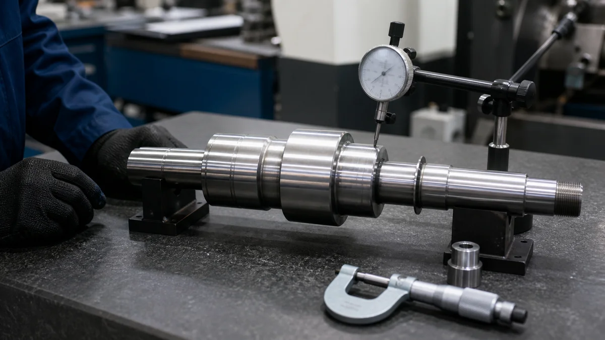
Blanket precision turns every diameter into a setup and inspection risk. It can require extra finishing passes, more controlled reclamping, specialized workholding, repeated machine checks, and broader reporting where the surface never contacts a mating component. The burden grows when controlled features sit on opposite ends of the part or cross multiple setups.
| Feature function | Drawing treatment to consider | Manufacturing consequence |
|---|---|---|
| Bearing journal | Runout to the functional bearing datum, plus required size and finish | Controls rotating support and may justify single-setup finishing |
| Sealing diameter | Local runout and surface-roughness callouts | Protects sealing without tightening unrelated surfaces |
| Locating bore | Datum designation or controlled coaxial relationship | Establishes assembly and inspection alignment |
| Clearance diameter | Suitable general size tolerance | Avoids unnecessary geometric inspection |
| Cosmetic turned surface | Appearance requirement or ordinary machined finish | Separates visual acceptance from rotating accuracy |
| Relief or undercut | Functional size, access, and edge requirements | Maintains clearance without imposing irrelevant runout control |
Specification mistake: Applying the same tight total-runout limit to two bearing journals, a clearance groove, a decorative diameter, and a hidden relief tells the supplier to treat every surface as functionally equivalent. The whole process may then be planned around the most difficult cross-setup relationship.
Classify features as functional, assembly-related, cosmetic, or non-critical. Establish the datum axis from how the component locates in service, then apply explicit controls only to relationships protecting fit, sealing, rotation, or alignment. Ordinary dimensions can remain under an appropriate general tolerance8 in the drawing notes or title block.
When a critical surface crosses setups, request the proposed relocation, finishing, and inspection strategy. Compare quotations on that complete scope rather than on machine rate or unsupported tolerance claims.
What Should a Concentricity and Runout RFQ Include?
Submit both design data and production context so the supplier can evaluate datum strategy, setup count, workholding, finishing, and inspection. The RFQ should identify the functional axis, critical diameters, geometric controls, material, quantity, production intent, revision, documentation, and delivery expectations.
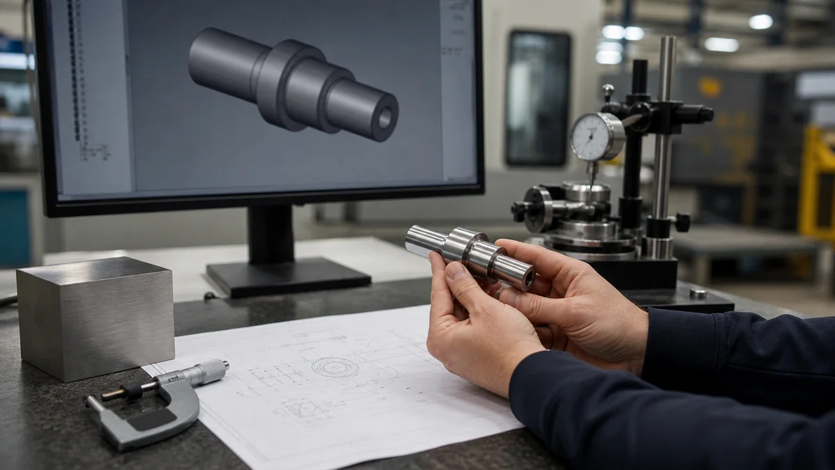
Use this complete CNC turning RFQ checklist9 before releasing the request:
- ☐ Supply a complete 3D CAD model matching the quoted geometry.
- ☐ Supply a controlled 2D drawing with part number, units, governing drawing standard, and active revision.
- ☐ State the exact material grade and condition, including heat treatment or supplied stock condition where applicable.
- ☐ Give the immediate quantity and identify prototype, pilot, repeat-production, or projected annual demand context.
- ☐ Define the functional datum feature and datum axis used for machining and inspection.
- ☐ Identify bearing journals, sealing diameters, locating bores, shoulders, mating faces, and other critical rotating interfaces.
- ☐ Assign circular runout, total runout, or concentricity only where the function requires it.
- ☐ State size tolerances separately and localize surface-finish requirements to the applicable features.
- ☐ Identify features intended for one setup and acceptable flips, transfers, cross-holes, milling, grinding, or other secondary operations.
- ☐ Provide minimum wall thickness, longest unsupported span, restricted gripping areas, and acceptable fixture witness marks.
- ☐ Define the inspection characteristic, datum, measurement locations, delivered condition, sampling frequency, and required reports.
- ☐ State secondary finishes and whether critical dimensions apply before or after finishing.
- ☐ Include delivery expectations, packaging concerns, sample approval needs, and required documentation.
- ☐ Resolve model-and-drawing conflicts and identify which document governs.
Name the process correctly. CNC turning is CNC machining that removes material from rotating stock. CNC turret punching uses programmed punch tools on sheet metal. Metal stamping cuts or forms sheet with dedicated dies. Sheet metal fabrication may combine cutting, punching, bending, welding, and finishing. Plastic injection molding forms polymer in a mold. These routes are not interchangeable, and “CNC turret punching, CNC punch press, CNC-controlled stamping equipment, or metal stamping depending on the actual process” is not one standard process term.
A complete package lets each supplier quote the same manufacturing, finishing, and inspection scope instead of adding different assumptions about datum and setup risk.
Send the supplier your 3D model, controlled 2D drawing, material grade and condition, quantity, prototype or production intent, datum axis, critical tolerances, runout or concentricity callouts, surface finish, inspection expectations, revision level, and delivery requirements. With those inputs, the supplier can recommend a setup and measurement plan, prepare a sample route, or quote against defined assumptions.
References
-
Circular Runout (GD&T) Explained - The datum axis acts as an anchor for the tolerance zone in circular runout. The callout creates a 2D circular tolerance zone around the ... ↩
-
Metal Cutting: Turning Machines and Centers - SME - Axis traverse rates are 45 m/min in the X direction and 30 m/min in theZ direction. A single part can be sequentially processed by moving it ... ↩
-
An efficient approach for the identification of candidate ... - by SH Cheraghi · 2003 · Cited by 6 — ASME Y14.5.1M-1994 standard specifies a procedure for the establishment of candidate datum set for a nominally flat datum feature. Implementation of this ↩
-
Dimensioning and Tolerancing of Flexible Parts - We use ASME Y14.5-2009 as our standard for rigid and nonrigid parts (subject to free state variation - like sheet metal parts, etc) ↩
-
Robust Machine Tool Thermal Error Modeling Through ... - The most significant factor influencing the machine tool accuracy is the thermal error, which accounts for 40–70% of total machine tool errors (1). Internal and ... ↩
-
GD&T Symbol - Circular Runout | ASME Y14.5 Symbols - Circular runout tolerance zones for cylindrical features are now defined as 2 circles coaxial to each other and the datum axis, as well as normal to the datum ... ↩
-
Smart Manufacturing Operations Planning and Control ... - This program will enable smart manufacturing based on performance metrics and process control, prognostics and health management (including ... ↩
-
Standard Tolerances in Manufacturing: ISO 2768 & ISO 286 - ISO 2768 provides general tolerances for linear and angular dimensions when specific tolerances are not indicated on the engineering drawing. ↩
-
CNC Machining RFQ Template Guide - uneed - CNC Machining RFQ Template Guide: Get faster quotes! Use our checklist for tolerances, parts, and materials. Simplify your CNC machining quoting process. ↩