
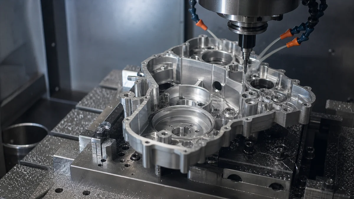
Thin-walled CNC machined parts can reduce weight, preserve clearance, and fit compact assemblies. The tradeoff is lower stiffness. A wall that looks sound in CAD may move under cutter pressure, distort when clamped, chatter during finishing, or change shape after release.
Wall thickness is therefore only the starting point. Material grade, unsupported height, transitions, internal radii, tool access, workholding, tolerance, surface finish, inspection method, and production intent all influence whether the feature can be produced and verified consistently.
The following design decisions turn those interacting risks into specifications that a machinist can evaluate, quote, and inspect.
What Makes a Thin-Walled CNC Machined Part Difficult to Produce?
A thin-walled CNC machined part becomes difficult when material removal leaves a section too flexible to resist cutting, vibration, heat, and clamping forces. The risk depends on wall geometry, material condition, support, tool access, tolerance, surface finish, and how the released part will be inspected.
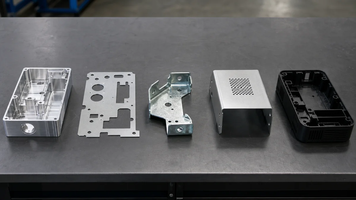
CNC machining1 creates a wall by cutting away the stock around it. As the remaining section becomes thinner or taller, its stiffness falls. Cutter pressure can push the wall away from the programmed path, while concentrated fixture pressure can deform it before cutting begins. The practical consequences include chatter, variable thickness, poor finish, and movement after unclamping.
That operating principle separates machining from processes that begin with sheet or form material in a mold:
| Process | How the shape is made | Specifications that commonly control thin features |
|---|---|---|
| CNC machining | Removes material from solid stock by milling, turning, drilling, boring, or reaming | Wall thickness, unsupported height, tool access, clamping, tolerance, and finish |
| CNC turret punching or CNC punch press | Uses programmed punch tools on sheet metal | Sheet thickness, hole and form geometry, burr direction, tool clearance, and later bends |
| Metal stamping | Cuts or forms sheet with dedicated dies | Die geometry, forming direction, springback, material condition, and production volume |
| Sheet metal fabrication | May combine cutting, punching, bending, welding, and finishing | Bend access, bend radius, joints, burr direction, and assembled stiffness |
| Plastic injection molding | Forms polymer inside a mold | Draft, wall uniformity, gate location, flow, cooling, shrinkage, and tooling |
“CNC turret punching, CNC punch press, CNC-controlled stamping equipment, or metal stamping depending on the actual process” is not one standard process term. An RFQ using it should clarify whether the intended process is CNC turret punching, a CNC punch press, CNC-controlled stamping equipment, or general die stamping.
Treat a machined wall as a flexible feature emerging from solid stock. If the part is fundamentally a bent enclosure or molded housing, compare processes deliberately; machining rules should not be transferred to sheet metal or molding without accounting for their different design constraints.
How Should Material Affect the Minimum Wall Thickness?
Set minimum wall thickness from the actual material grade and condition, then review it against wall height, surrounding support, finish, tolerance, and workholding. Baseline values help early design and quotation, but they do not establish a universal capability for every supplier, material condition, or geometry.
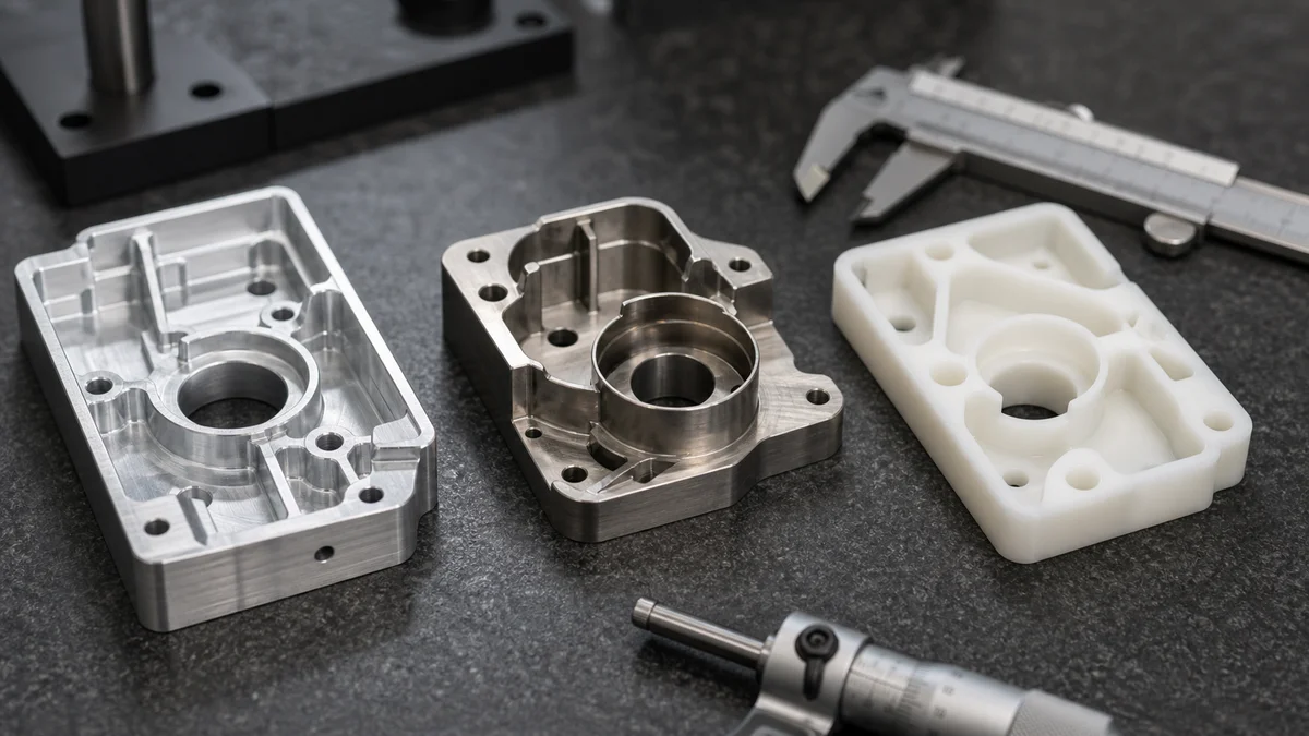
Materials respond differently to cutter pressure, heat, chip formation, and clamping. A wall that is workable in one material may be unstable in another. The drawing should therefore state the material grade and condition instead of using only “metal,” “aluminum,” or “plastic.”
The supplied research supports these preliminary design-for-manufacturing references2:
| Machined material | Preliminary wall-thickness reference | Details requiring supplier review |
|---|---|---|
| Milled aluminum | About 0.8 mm | Alloy, temper, wall height, pocket depth, finish, and clamping strategy |
| Stainless steel | At least 1.0 mm | Tool engagement, heat, rigidity, access, and required surface condition |
| Machined plastic | At least 1.5 mm | Clamp deformation, warping, temperature sensitivity, and material behavior |
These are discussion points, not guaranteed limits. A short wall supported on three sides is not equivalent to a long free-standing flange of the same thickness. A clearance wall with a general tolerance also presents less specification risk than a sealing wall with tight profile and roughness requirements.
Example: A 0.8 mm aluminum wall callout should be accompanied by the alloy and temper, unsupported height, adjacent pocket depth, critical faces, local finish, and inspection condition. Without those details, the nominal thickness does not define the machining risk.
When a design falls below the relevant reference, flag the region and request supplier review. The process may require added support, purpose-designed workholding, light finishing cuts, or development trials. In some geometries, another manufacturing route may deserve comparison. Define the required function and acceptance criteria, but avoid prescribing unsupported cutter settings or claiming that one minimum applies to every shop.
How Should You Limit the Height-to-Thickness Ratio of an Unsupported Wall?
Evaluate unsupported wall height together with thickness because a tall wall can deflect even when its nominal thickness meets a general guideline. Ratios from 3:1 to 10:1 are conservative design references, while an unsupported ratio above about 15:1 may be impractical for standard CNC machining.
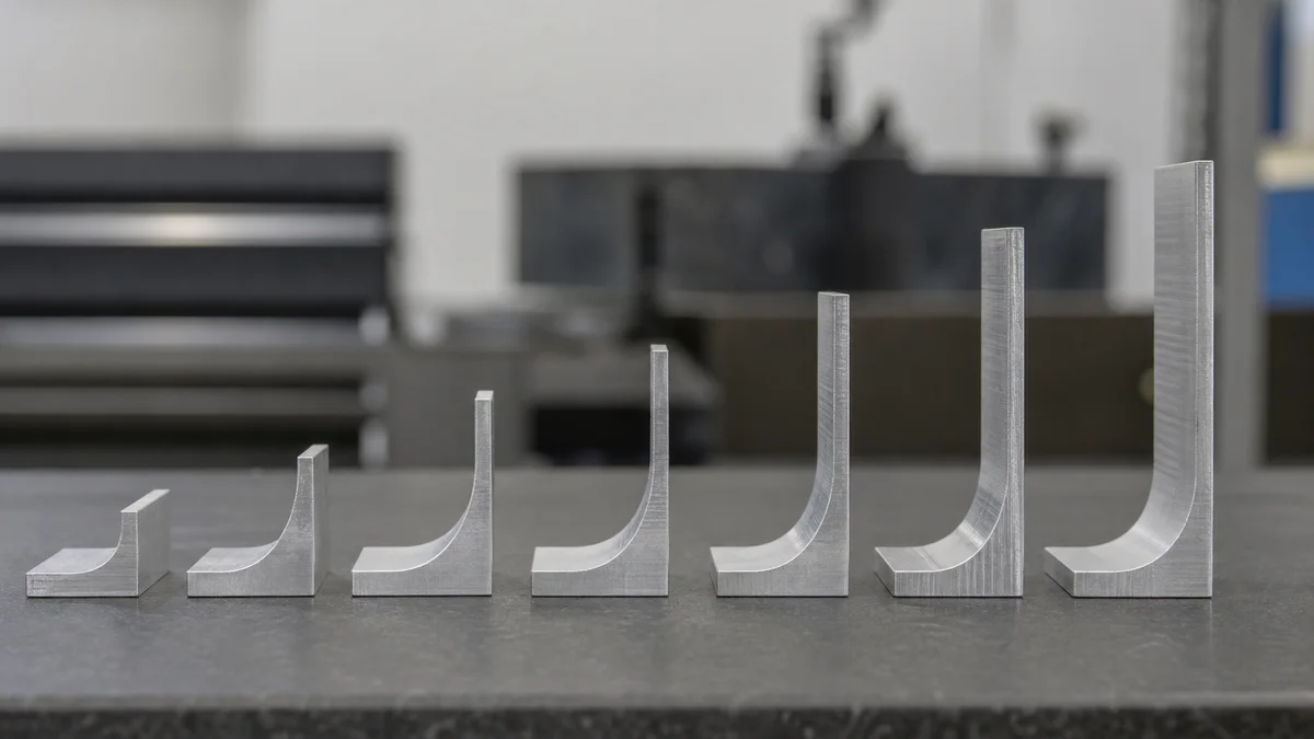
Calculate the wall height-to-thickness ratio3 by dividing unsupported height by wall thickness. This is a useful screening check because two walls with the same thickness can respond very differently when one extends much farther from its supported base.
A lower ratio generally gives the cutter a more rigid feature. As the ratio increases, cutting force has greater leverage to bend the wall. Material, total wall length, curvature, ribs, base geometry, cutter access, removal sequence, tolerance, and surface finish still matter, so the ratio is a DFM signal rather than a stand-alone acceptance rule.
What should change when the ratio is high?
Possible responses include shortening or thickening the wall, adding ribs or gussets, dividing a long span into supported sections, or changing the component into a machined base with an attached feature. Sheet metal fabrication may merit comparison when the geometry is fundamentally a thin panel. That is a different process decision, however, with its own bend access, burr direction, joining, and springback requirements.
Scenario: Consider a 1 mm wall extending 18 mm above its base. Its 18:1 unsupported ratio exceeds the research reference for standard machining, even though 1 mm may not look unusually thin in isolation. This teaching scenario does not establish a supplier limit. It signals the need to reduce the height, retain a support, increase thickness, divide the span, or obtain a documented machining and inspection proposal.
The drawing should make the start and end of the unsupported height clear. It should also identify whether the wall controls assembly, sealing, alignment, appearance, or only clearance. That functional classification determines whether redesign, added process effort, or a relaxed tolerance is the more sensible response.
When Should Thin Walls Use Permanent or Removable Supports?
Use permanent ribs, gussets, or flanges when they support both machining and final function. Use removable bridges or sacrificial ribs when rigidity is needed only during material removal. In either case, define the support geometry, status, finished surface, and removal access in the model and drawing.
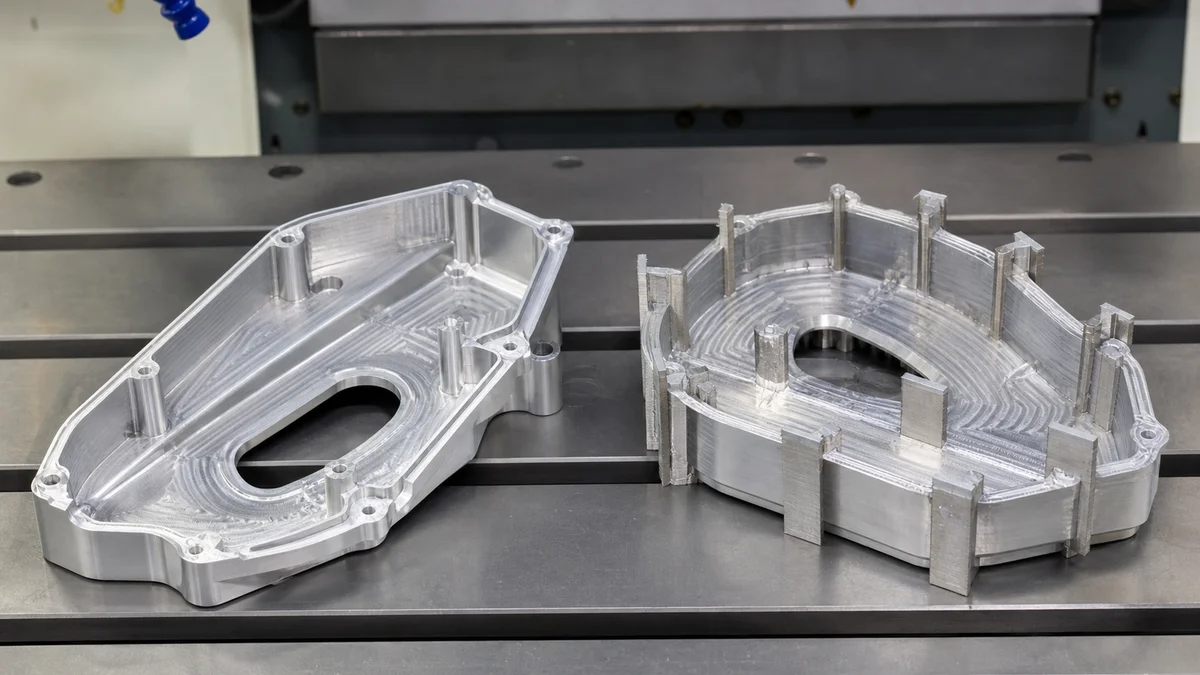
A support reduces unsupported span and helps a wall resist cutter pressure. Permanent supports remain on the delivered component, so they must suit assembly clearance, weight, cleaning, finish, and service requirements. Temporary supports stabilize machining but introduce a separate removal and cleanup operation.
The research provides two starting references for ribs: thickness around 50–60% of the main wall and a rib height-to-thickness ratio below about 3:1. These are conditional design references, not universal dimensions. Final rib geometry depends on material, wall length, tool access, service loading, and whether the rib creates an inaccessible corner or obstructs inspection.
Before releasing supported thin-wall geometry, confirm:
- Whether each rib, gusset, flange, or bridge remains on the finished part.
- Which surfaces and datums define the final condition after temporary material is removed.
- Whether a cutter can reach the full support interface for cleanup.
- Whether removal could leave a remnant, sharp edge, or undefined blend.
- Whether a permanent support interferes with mating parts, drainage, cleaning, coating, or inspection.
- Whether dimensions apply before or after sacrificial support removal4.
Scenario: A temporary bridge ties the top of a thin flange to the main body during roughing. The drawing marks it as sacrificial and defines the final flange profile. If another feature blocks the cleanup path, the bridge cannot be removed completely. The design has traded a stiffness problem for a tool-access and acceptance problem.
Design temporary supports backward from the final removal cut. The supplier should retain freedom to propose the detailed sequence, but the controlled documents must leave no doubt about what stays, what goes, and which surface is inspected.
How Should Wall Transitions and Internal Radii Be Designed?
Keep wall thickness reasonably uniform, blend abrupt transitions, and specify practical internal radii at wall bases and pocket corners. These choices distribute cutting loads and permit more rigid cutters. Radius references of 0.5–1.0 mm support early design, but the final value should reflect depth and access.
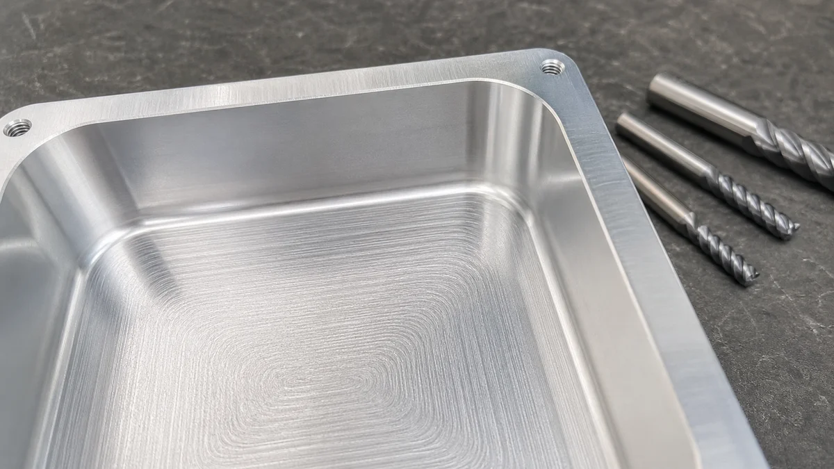
Sudden thickness changes produce uneven stiffness. Under cutter pressure, a thin segment can move more than the heavy section beside it, while an abrupt junction can concentrate stress and complicate balanced material removal. Where function permits, use gradual blends, consistent wall sections, and supported junctions instead of alternating sharply between heavy and delicate geometry.
Internal corners need separate attention because a rotating milling cutter cannot produce a perfectly sharp internal corner. A smaller radius usually requires a smaller cutter. At a comparable reach, that cutter is less rigid and more sensitive to deflection than a larger tool. The problem grows in deep pockets, where the cutter must extend farther from its holder.
The supported 0.5–1.0 mm internal radius range5 is useful for early review at wall bases and pocket corners. It should not be copied blindly across the part. Cavity depth, mating clearance, acceptable residual corner material, finish, and available access should guide the final value. When assembly geometry permits, a larger radius may allow a more rigid tool and a less abrupt load path.
Does the corner truly need to be sharp?
If a mating component occupies the corner, check whether that part can use a chamfer, relief, or corresponding radius. Secondary corner cleanup should be required only when the sharp condition serves a defined function.
A common specification mistake is showing a nominally sharp CAD corner while the drawing neither assigns a radius nor permits cutter-generated corner material. The supplier must then assume a tool size or request clarification. A stated radius, supported by clear mating intent, makes the geometry quotable and inspectable without forcing unnecessary micro-tooling.
How Should the Part Provide Tool and Fixture Access?
Provide stable clamping regions away from delicate walls and preserve access for the largest, shortest practical cutter. Identify functionally critical faces and feature relationships, but let the supplier choose soft jaws, backing supports, distributed clamping, removable supports, and the detailed machining sequence.
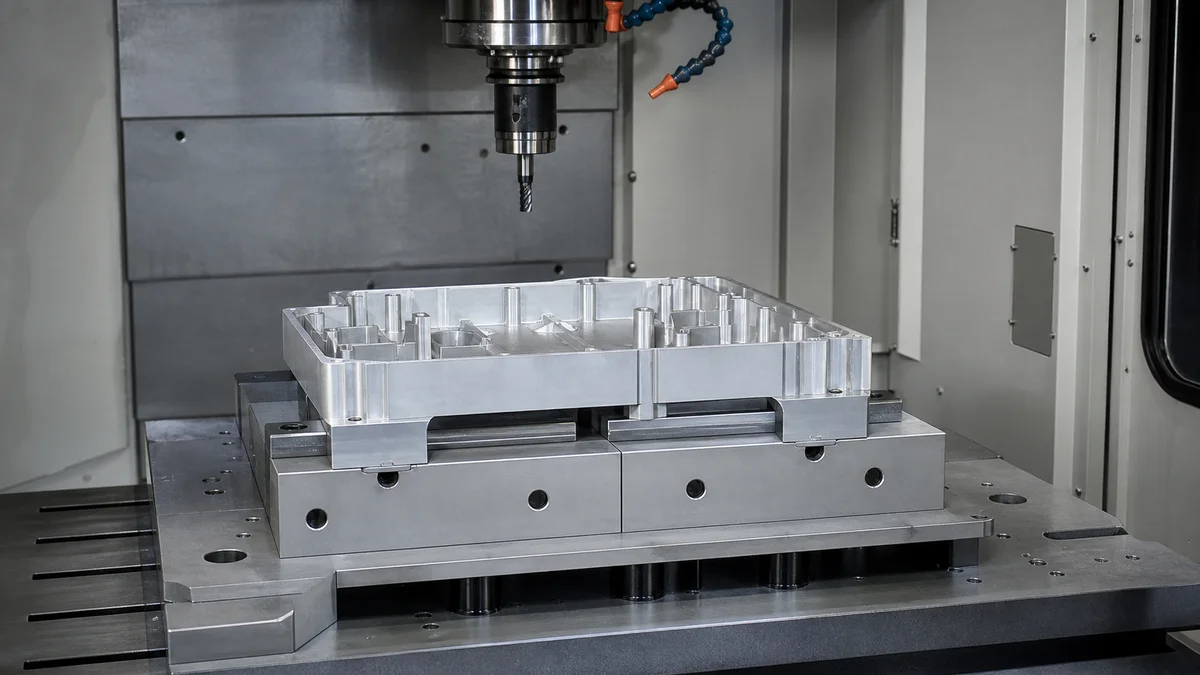
Tool access and fixture access compete for the same space. Opening a pocket for a cutter may remove stock that could otherwise support the part. If every external surface is thin, cosmetic, or obstructed, controlled workholding may require additional planning before machining starts.
Review the design with these questions:
- Are there thick datum faces, bosses, or stock regions that can accept distributed clamping force?
- Can fixture contact avoid walls that may deform elastically?
- Does nearby geometry force a long, small-diameter cutter into a deep pocket?
- Which holes, faces, and profiles must remain aligned across separate setups?
- Are any cosmetic or no-clamp surfaces protected from fixture contact?
- Can the supplier reach the part for deburring, support removal, finishing, and inspection as well as rough machining?
Short tool reach and larger cutter diameter generally improve rigidity. The product drawing does not need to prescribe cutter selection, feeds, speeds, coolant, or fixture construction. It should communicate the geometry, datums, finish restrictions, and functional relationships that constrain those process choices.
When several critical features are produced from one orientation, their relationship is generally easier to manage than one that crosses multiple setups. If repositioning is unavoidable, identify the relationship that matters—such as face-to-bore alignment or profile relative to a datum—rather than specifying a machine configuration by habit.
Soft jaws, backing supports, distributed clamping, or removable cavity support may be appropriate. Their fit depends on part envelope, material, quantity, finish, and access. Ask the supplier to propose the workholding strategy6; avoid turning an unverified fixture concept into a mandatory product requirement.
How Should Tolerances, GD&T, and Inspection Be Specified on Thin Walls?
Apply close thickness, flatness, profile, and surface-finish requirements only to features that affect fit or function. Use clear datums and an agreed inspection condition because fixture pressure, temperature, and residual stress can change a thin wall’s measured shape after machining and release.
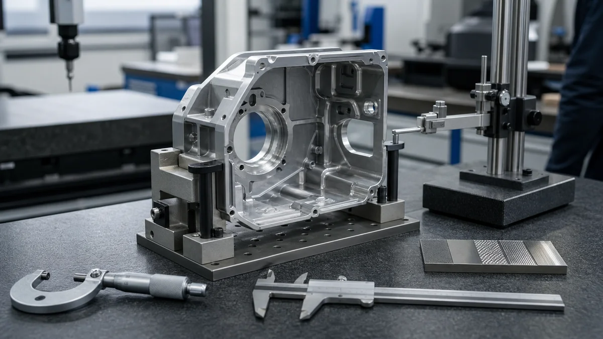
A blanket tight tolerance makes every thin surface appear functionally critical. A better drawing separates functional, assembly, cosmetic, and non-critical features. Bilateral thickness tolerances can express acceptable variation around a nominal size, while GD&T can control form and relationships without shrinking every linear tolerance and creating unnecessary tolerance stack-up.
| Controlled characteristic | Functional reason | Drawing information needed | Inspection decision |
|---|---|---|---|
| Wall thickness | Controls clearance, mass, or structural section | Nominal size, bilateral tolerance, and measurement locations | Number and distribution of readings |
| Flatness | Face must seat, seal, or remain within a form boundary | Tolerance zone and applicable surface | Restrained, fixture-held, or free-state measurement7 |
| Profile of a surface | Complete wall shape matters relative to other features | Datum reference frame and profile boundary | Measurement coverage and reporting method |
| Surface finish | Local area supports sealing, sliding, appearance, or coating | Ra value and exact application area | Whether roughness is measured and recorded |
| Position or related GD&T | Hole or feature must align with a datum-controlled interface | Datums, feature callout, and material condition if applicable | Required method, sampling, and evidence |
For many non-critical aluminum features, ±0.10 mm to ±0.13 mm can serve as a practical general tolerance baseline when closer control is unnecessary. It remains geometry- and supplier-dependent. A requirement below about ±0.05 mm becomes a process and inspection decision that should be tied to a named feature and function.
State whether inspection requires first-article results, in-process checks, batch sampling, final dimensional reports, or selected full inspection. Define whether acceptance occurs while restrained, in an agreed fixture, or after release and stabilization. For tight aluminum dimensions, also clarify the reference temperature or ask how thermal effects will be managed.
Localize fine Ra requirements and state whether dimensions apply before or after anodizing, plating, or another finish when buildup could affect acceptance.
What Should an RFQ Include for Thin-Walled CNC Machined Parts?
A thin-wall RFQ should define geometry, material, production intent, critical features, finish, and inspection expectations. Mark delicate regions and ask the supplier to review wall thickness, unsupported height, support strategy, tool access, workholding, tolerance feasibility, cost drivers, and delivery risk before approval.
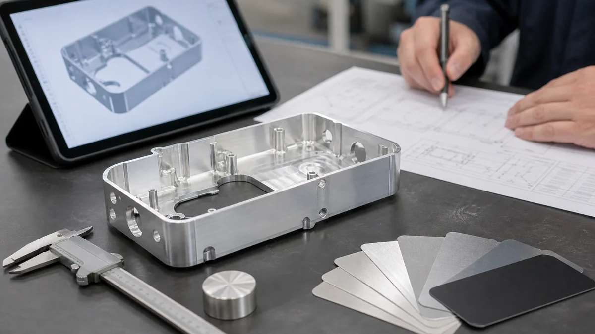
Thin walls magnify risks that may be minor on a rigid part. Chatter, clamp deformation, residual-stress movement, poor finish, and dimensional drift become more likely when a feature is thin, tall, inaccessible, difficult to support, or tightly specified. Custom workholding, light finishing passes, development trials, secondary finishing, and structured inspection can affect both cost and schedule.
Use this RFQ and design-approval checklist:
- 3D CAD model: Include complete geometry and identify the active revision.
- Controlled 2D drawing: Define units, datums, wall dimensions, critical features, GD&T, threads, radii, finish locations, and drawing revision.
- Document authority: State which document governs if the model and drawing disagree.
- Material grade and condition: Specify the exact grade, temper or condition, and any material-documentation requirement.
- Quantity and demand: State the immediate quantity and estimated annual usage when known.
- Production intent: Distinguish prototype learning, functional validation, pilot production, and repeat production.
- Thin-wall classification: Mark each delicate region as functional, assembly-related, cosmetic, or non-critical.
- Geometry risks: Highlight minimum thickness, unsupported height, long spans, deep pockets, restricted tool access, and cross-setup relationships.
- Support intent: Distinguish permanent ribs from sacrificial material that must be removed.
- Critical tolerances and GD&T: Localize thickness, flatness, profile, position, and datum requirements.
- Surface finish and secondary operations: Show where each requirement applies and whether dimensions are before or after finishing.
- Inspection expectations: Define measurement condition, inspection scope, sampling, first-article needs, and required reports.
- Delivery expectations: Provide the requested timing, shipment assumptions, and approval stages.
- Supplier DFM feedback8: Request comments on feasible wall geometry, setup strategy, inspection method, cost drivers, and practical alternatives.
This information lets the supplier recommend a workable process and expose exceptions before approval. It is more useful than forcing one machining method onto incomplete geometry.
For a manufacturability recommendation or quotation, send the 3D model, controlled 2D drawing, material grade and condition, quantity, prototype or production intent, critical tolerances, surface finish, inspection expectations, revision level, and delivery requirements. Mark every thin-wall region that affects fit, sealing, alignment, or appearance.
References
-
Dynamic Problems in Hard Turning, Milling and Grinding | NIST - We focus on three practical machining processes turning of hardened steels (hard-turning), high-speed milling, by increasing material removal ... ↩
-
Minimum Wall Thickness for CNC Machining - LK Prototype - For metals like aluminum, a minimum of 0.8 mm works well. Stainless steel and titanium need at least 1.0 mm. Plastics require 1.5–2.0 mm for ... ↩
-
Thin Wall CNC Machining: Process, Deformation & Cost - JLCCNC - In CNC manufacturing, a wall is typically considered “thin” when its thickness is small relative to its unsupported height or length. ↩
-
Minimum Wall Thickness CNC, Aluminum Milling & Deformation ... - External support methods and when to add sacrificial backing (Examples: backing plates, temporary support features). External support is often the difference ... ↩
-
CNC Machining Design Guideline - JLCCNC - Currently, we can achieve a minimum internal radius of R 0.5 (mm) with a depth of ≤3 (mm). Smaller internal radii require smaller cutting tools, ... ↩
-
Tooling and Workholding - SME.org - Rotomors Six-Jaw Chuck: Ideal for thin wall, out of round or powdered metal parts, this six-jaw chuck grips at more contact points on the part, ... ↩
-
Flexible Parts | Geometric Dimensioning and Tolerancing Handbook - About free state variation. 4. That part should be inspected in the way that they function. 5. To apply temporary datum features for in-process inspection. ↩
-
CNC Machining RFQ Checklist: Get Faster, Accurate Quotes - 1) Send both the drawing and the 3D model (when available). Best combo: 2D drawing (PDF) with dimensions, tolerances, notes, revision, and date. ↩