

Weld lines, short shots, and burn marks can appear on the same molded component, but each points to a different physical mechanism. A short shot is incomplete cavity filling. A weld line forms where separate resin flow fronts meet. A burn mark may result from trapped-air heating, excessive shear, or another localized thermal condition.
Reliable diagnosis starts with the defect location and fill sequence—not simultaneous changes to temperature, speed, and pressure. Connect the symptom to the resin grade, wall thickness, gates, vents, cavity, material delivery, and the affected functional or cosmetic feature.
The workflow below moves from classification and fill mapping to controlled venting tests, tooling decisions, measurable sample acceptance, and a troubleshooting RFQ that gives molders enough evidence to recommend corrective action.
How Can You Distinguish Weld Lines, Short Shots, and Burn Marks?
Classify the defect by its visible form, location, and relationship to the cavity fill sequence. Incomplete geometry indicates a short shot, a seam where separate flow fronts meet indicates a weld line, and localized brown or black discoloration commonly points to trapped-air heating or excessive shear.
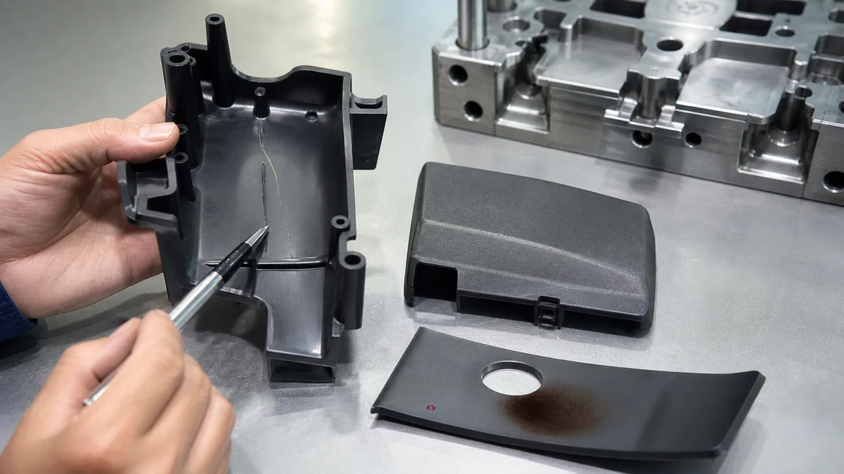
Begin by recording what is visible without assigning a cause. Note the mold and cavity, defect position, affected surface, gate location, nearby vent, and surrounding geometry. Ribs, bosses, holes, deep pockets, thin walls, and abrupt wall transitions can redirect resin or determine where air becomes trapped.
| Observed condition | Mechanism to investigate first | Evidence to record |
|---|---|---|
| Missing material or incomplete feature | Cavity did not fill | Shot size, cushion, transfer position, last-to-fill location |
| Seam joining two resin paths | Separate flow fronts met | Gate layout, flow path, melt and mold conditions, venting |
| Localized brown or black mark | Trapped-air heating or excessive shear | End-of-fill position, vent condition, fill-speed profile |
A defect may have several contributing conditions. Poor venting, for example, can stop resin from filling a blind rib, weaken fusion where flow fronts meet, or heat compressed air enough to discolor the surface. This is why defect location often carries more diagnostic value than the defect name alone.
A common specification mistake is directing the molder to increase pressure before documenting the symptom. More pressure may not overcome a blocked air-escape path and can erase useful baseline evidence. Freeze the current process record, photograph representative parts from a consistent orientation, and classify the affected feature as functional, assembly-related, cosmetic, or non-critical before choosing the next test. This disciplined defect classification1 keeps process changes tied to an observable mechanism.
What Should You Check First When Diagnosing a Short Shot?
Start short-shot diagnosis by confirming mold cleanliness, delivered resin, shot size, cushion, and first-stage transfer position. Check feed restriction and non-return performance before changing the gate. Evaluate speed, pressure limits, temperatures, venting, and local geometry only after material delivery is shown to be stable.
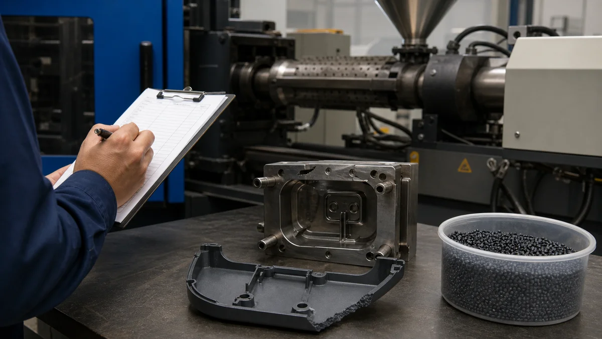
A short shot does not automatically prove that the gate is undersized or that more injection pressure is required. The process may be transferring too early, delivering an inconsistent volume, or losing effective shot volume through a worn check ring or non-return valve. Resin feed restriction or contamination can produce a similar underfilled result.
Use this complete short-shot diagnostic checklist before authorizing gate or mold changes:
- ☐ Confirm that the mold, gate region, and relevant vents are clean.
- ☐ Verify the exact resin grade, additives, filler, color, and conditioning against the approved setup.
- ☐ Record shot size and confirm that the cushion is present and repeatable.
- ☐ Check first-stage transfer position. Approximately 95% to 98% fill before transfer is a process-development reference, not a universal production setting.
- ☐ Compare consecutive cycle weights or another agreed delivery indicator for consistency.
- ☐ Investigate feed restriction and check-ring or non-return performance if delivery varies.
- ☐ Review injection speed and applicable pressure limits without changing both simultaneously.
- ☐ Check melt temperature and mold temperature against the approved resin-specific process record.
- ☐ Inspect local venting, gate restriction, wall thickness, and the last-to-fill geometry.
- ☐ Preserve baseline samples, cavity identification, photographs, and settings before the next trial.
If shot weight, cushion, or the short location varies, material delivery or machine consistency deserves attention. If every shot stops at the same thin wall, rib, boss, or deep pocket, a local flow restriction, premature freeze-off, or air trap becomes more likely.
Common mistake: enlarging the gate before completing the documented material-delivery check2. That permanent modification changes filling and packing behavior while leaving a feed, transfer, or non-return problem unresolved.
How Should You Map the Last-to-Fill Region?
Create a fill map by molding progressively fuller parts and recording where each flow front stops. A short shot that repeatedly ends at one rib, boss, pocket, or thin section suggests a local restriction, trapped-air region, or premature freeze-off rather than random machine variation.

A fill map converts a finished-part defect into a visible sequence of flow events. Begin with a deliberately incomplete fill and increase the shot in controlled steps while holding the resin, mold, and other relevant conditions stable. Increments of about 10% and roughly 20 shots are possible diagnostic references, not required production specifications.
Record the following for every sample:
- Shot sequence, mold, and cavity identification
- Approximate fill stage or controlled shot setting
- Position of each advancing flow front
- First rib, boss, hole, pocket, or wall transition reached
- Locations where flow fronts divide and rejoin
- Last visible region to fill
- Any weld line, burn mark, hesitation, or incomplete feature appearing at that stage
Photograph every sample from the same orientation and preserve its sequence. Overlaying the results with the wall-thickness map and gate-and-vent layout makes flow hesitation easier to interpret. For multi-cavity tooling, keep the evidence cavity-specific because runner balance and vent condition may differ.
Scenario: A molded housing remains incomplete at the end of a blind rib. Progressive samples show the surrounding wall filling first while the rib becomes the final enclosed region. That repeatable pattern supports an air-escape test near the rib. If the stopping point moves unpredictably between cycles, unstable delivery or process variation should be reconsidered.
A progressive short-shot study3 does not prove the final cause by itself. It shows where to test next and provides a defensible basis for reviewing venting, gate placement, wall geometry, flow balance, or shot delivery.
Should You Test Venting Before Increasing Injection Pressure?
Yes. When incomplete fill occurs at an end-of-fill or blind feature, use a controlled temporary venting test before adding pressure. If improved air escape allows the feature to fill, venting is the stronger diagnosis and permanent changes should focus on vent position, condition, and geometry.
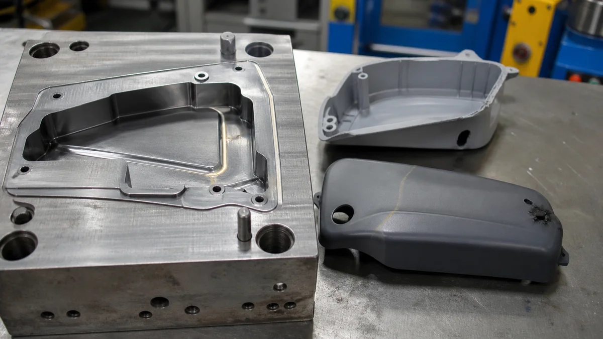
Pressure can advance resin only when displaced air has a viable escape path. At a blind rib, dead pocket, or end-of-fill region, trapped air can resist the flow front. Raising pressure without improving air escape may leave the short shot unchanged or compress and heat the trapped air until a burn mark appears.
A temporary vent or controlled ejector-pin-hole test can provide useful evidence. The mold supplier should approve the test because the safe location and geometry depend on the available mold steel, parting line, ejector layout, flash risk, and finished-surface requirement. Preserve the original condition, document the temporary change, and compare samples under otherwise stable settings.
What should be inspected after the test?
Compare feature completion, short-shot location, burn evidence, flash, and cycle-to-cycle repeatability. Inspect the existing vent for contamination, carbon buildup, crushing, inadequate depth, unsuitable land length, and poor connection to the outside evacuation path. A successful test supports venting as the mechanism, but it does not automatically define a durable production vent.
Scenario: A deep corner remains consistently short. A controlled temporary escape path allows that corner to fill without raising the pressure limit. This teaching result supports permanent vent review rather than immediate gate enlargement. If the test produces no meaningful change, return to shot delivery, premature freeze-off, gate restriction, resin condition, and temperature review.
Changing speed, pressure, temperature, and venting together destroys the comparison. A one-variable venting trial4 preserves traceable evidence and reduces the chance of replacing a short shot with a burn.
How Should Vent Dimensions Be Matched to the Resin?
Review vent depth and land length against the exact resin rather than copying another mold. Resin family, grade, additives, flow behavior, geometry, vent position, and supplier practice all affect the suitable condition. Published dimensions are diagnostic benchmarks requiring tool-specific confirmation, not universal mold specifications.

A vent must release displaced air while limiting resin leakage and flash. A shallow, blocked, or crushed vent may trap air. A vent that is too deep for the resin and local pressure can create flash or another unacceptable parting-line condition.
The supplied research provides these concrete audit references:
| Resin family | Vent-depth reference | Vent-land reference | Audit use |
|---|---|---|---|
| Nylons and polyolefins | 0.0005–0.0015 in. | 0.060–0.080 in. | Compare with measured tool condition |
| ABS | 0.0015–0.0030 in. | 0.060–0.080 in. | Review with flash and end-of-fill evidence |
| Polycarbonate | 0.0007–0.0012 in. | 0.060–0.080 in. | Check against the exact grade and additives |
Treat these resin-specific vent benchmarks5 as inspection references only. The exact grade, filler content, wall thickness, flow length, gate strategy, end-of-fill pressure, surface-finish requirements, and allowable flash condition can change the appropriate design.
Depth is only one part of the escape route. Inspect the land, relief beyond the land, vent location, connection to atmosphere, and maintenance condition. A correctly dimensioned vent can still fail when residue blocks it. Cleaning alone will not solve a vent that misses the actual air trap.
For a tool audit, identify every relevant vent by location and record its measured depth, land length, connected relief, cleaning history, cavity, resin, and associated defect. This evidence helps the toolmaker decide whether maintenance, a local modification, or a broader gate-and-flow revision is justified.
How Can You Separate Trapped-Air Burns from General Overheating?
A burn fixed at a dead pocket, vent, or last-to-fill region is more consistent with trapped-air heating than broad overheating. Compare its position with the fill map, inspect carbonized vents, and test a controlled reduction in end-of-fill speed before changing the overall melt-temperature profile.

Trapped-air heating, often called dieseling, occurs when advancing resin rapidly compresses air that cannot escape. The resulting brown or black mark is usually localized at an air trap. General thermal degradation may require a wider material, residence-time, and temperature investigation, but defect location is the strongest first separator supported here.
Follow this evidence sequence:
- Compare the mark with the last-to-fill region on the fill map.
- Confirm whether it remains anchored to the same cavity and feature.
- Inspect nearby vents for carbonized residue, blockage, crushing, or an incomplete evacuation path.
- Review whether a dead pocket, enclosed rib, boss, or obstructed geometry traps air.
- Reduce fill speed near the end of injection as one controlled test.
- Preserve samples and process records before changing the overall temperature profile.
If slower end-of-fill movement reduces the mark while its position remains tied to an air trap, compressed-air heating becomes the stronger diagnosis. If discoloration is widespread, moves independently of the fill pattern, or follows changes in material residence or temperature, broaden the investigation. No single melt-temperature rule applies to every resin grade.
Example: A dark mark appears at the same enclosed corner in every sample, and the adjacent vent contains carbonized residue. Cleaning that vent and comparing controlled samples is more direct than reducing every temperature setting. If the defect returns, review the local vent path and pocket geometry. The durable correction may require maintenance, vent modification, or geometry changes rather than routine process compensation.
When Should a Weld Line Trigger Gate or Tooling Changes?
A weld line should trigger gate or tooling review when it crosses a snap, boss, rib, hole, flexing zone, sealing area, or load-bearing interface. Process tuning may improve fusion, but relocating the meeting point or changing flow balance is more durable when the line creates functional risk.
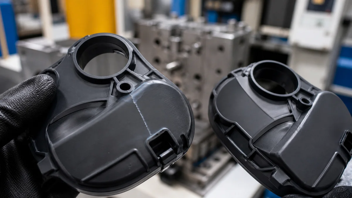
A weld line forms where resin streams divide around geometry or arrive from different directions and then meet. Fusion depends on the fronts' temperature, speed, pressure transfer, and venting at that location. Higher melt temperature, mold temperature, or injection speed may help when the fronts arrive too cold, but any adjustment must remain suitable for the exact resin and surface requirements.
| Weld-line location | Approval concern | Escalation if tuning is insufficient |
|---|---|---|
| Hidden, non-critical surface | Defined appearance and repeatability | Monitor or refine the stable process window |
| Visible cosmetic face | Appearance under specified viewing conditions | Review gate position or flow balance |
| Snap, flexing rib, or attachment | Local functional weakness | Move the meeting region or revise tooling |
| Boss, hole, seal, or loaded interface | Assembly, sealing, or structural risk | Gate relocation, overflow, weld tab, or geometry change |
A gate change influences more than the line itself. It can alter flow length, packing, gate vestige, venting, shrinkage orientation, warpage, and appearance. An overflow or weld tab may move the meeting region beyond the finished feature, but it adds mold construction, material removal, and inspection considerations.
Common mistake: approving a weld line solely because temperature adjustment makes it less visible. A cosmetically improved line may still cross the same loaded or flexing feature. The controlled drawing and sample plan should identify prohibited weld-line zones and distinguish functional, assembly-related, cosmetic, and non-critical surfaces. That functional weld-line review6 determines whether process tuning is enough or the flow path itself must change.
How Should Defect Inspection and Sample Acceptance Be Defined?
Define acceptance by defect type, cavity, location, affected feature, and functional consequence. Specify how weld lines, incomplete features, and burns will be inspected, which cosmetic and functional zones apply, what sample approval covers, and how frequently production evidence must be recorded.
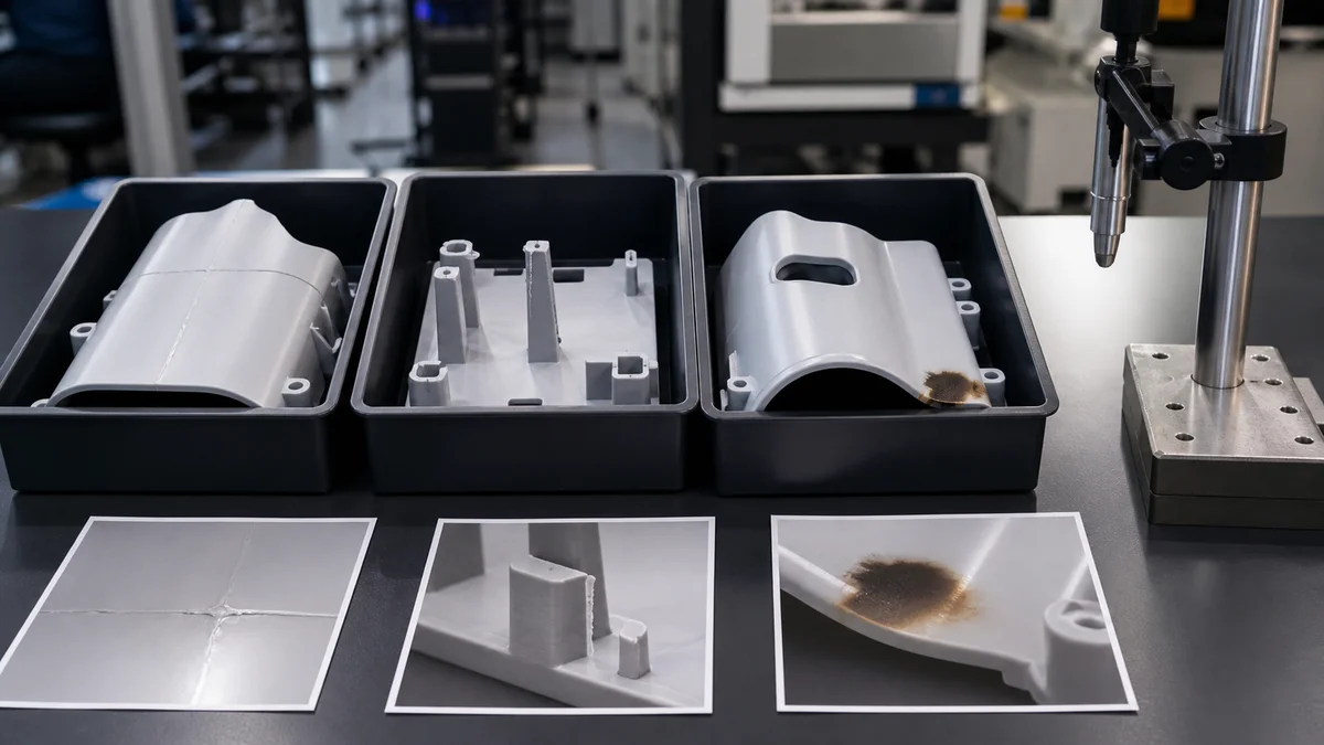
Notes such as “no marks,” “complete fill,” or “good appearance” do not create a repeatable approval basis. A weld line on a hidden cover surface differs from one crossing a snap. An incomplete decorative texture differs from an incomplete sealing or locating feature. Burn acceptance likewise depends on location, severity, repeatability, and its connection to an air trap.
Use this complete sample-approval checklist:
- Active part number, controlled drawing revision, and exact resin grade
- Mold, cavity, sample, lot, and inspection-date identification
- Defect type and location on a controlled photograph or drawing
- Functional, assembly-related, cosmetic, or non-critical zone classification
- Required completion of ribs, bosses, holes, edges, and molded details
- Acceptable and prohibited weld-line zones
- Cosmetic lighting, viewing direction, viewing distance, and approved comparison sample when used
- Critical dimensions, profiles, fits, or surfaces affected by the defect
- Measurement and conditioning state used for dimensional acceptance
- First-sample scope and confirmation that every required cavity is represented
- Production sampling frequency and cavity-specific records
- Required defect photographs, measured results, and nonconformance disposition
- Reapproval triggers after gate, vent, geometry, resin, tool, or process revisions
Example: A weld line approved on a hidden internal wall should not automatically be accepted on a flexing latch molded in the same cavity. The approval plan must map acceptance to feature function.
Inspection confirms conformance; it does not correct unstable filling, inadequate venting, or unsuitable gate placement. Repeated sorting should trigger process or tooling review rather than become the primary defect-control strategy. A cavity-specific acceptance plan7 keeps approval evidence connected to the actual defect mechanism.
What Information Should a Troubleshooting RFQ Include?
A troubleshooting RFQ should combine controlled product specifications with defect and process evidence. Send the model, drawing, exact resin, quantities, critical features, finish, inspection scope, revision, and delivery expectations, then add cavity data, gate and vent details, process settings, fill maps, photographs, and sample history.

State clearly that the project concerns plastic injection molding: molten polymer fills a mold cavity, cools, and is ejected. CNC machining removes material from solid stock. CNC turret punching uses programmed punch tools on sheet metal. Metal stamping uses dedicated dies, while sheet metal fabrication may combine cutting, punching, bending, welding, and finishing. “CNC turret punching, CNC punch press, CNC-controlled stamping equipment, or metal stamping depending on the actual process” is not one standard process term; clarify whether it means turret punching, a CNC punch press, CNC-controlled stamping equipment, or die stamping.
Use this troubleshooting RFQ checklist:
- 3D CAD model and controlled 2D drawing
- Active part number and revision, with the governing document identified if files conflict
- Exact resin grade, additives, filler, color, and approved alternatives
- Immediate quantity, expected annual demand when known, and prototype or production intent
- Wall-thickness map, ribs, bosses, pockets, thin sections, and critical flow geometry
- Critical tolerances, functional interfaces, and cosmetic zones
- Surface finish, texture, gloss, and permitted witness locations where relevant
- Gate type and location, runner arrangement, and gate-change restrictions
- Vent locations, measured depth, land length, evacuation path, and cleaning history
- Mold and cavity identification
- Shot size, cushion, transfer position, speed profile, pressure limits, and recorded temperatures
- Fill map, defect photographs, sample sequence, and previous corrective actions
- Inspection method, sample-approval scope, sampling frequency, and required reports
- Revision level, delivery expectations, and permission to propose process, vent, gate, or geometry changes
A complete injection molding evidence package8 lets suppliers distinguish cleaning, process development, tool modification, resampling, and design revision. Comparable recommendations and quotations require every supplier to review the same geometry, process history, inspection expectations, and production intent.
For a troubleshooting recommendation, sample plan, or quotation, send the 3D model, controlled 2D drawing, exact resin grade, quantity, prototype or production intent, critical tolerances, surface finish, inspection expectations, active revision, gate and vent data, process record, defect photographs, and delivery requirements.
References
-
Top 5 Most Common Quality Defects in Injection Molding - Causes and remedies for the top 5 quality defects in injection molding including weld lines, burn marks, short shots, sink marks, and flash. ↩
-
Injection Molding Cushion Variation - If you've experienced cushion issues in your injection molding process, you know the telltale signs: improper packing, insufficient pressure, ... ↩
-
Short Shot Defects in Injection Molding - A short shot defect occurs when molten plastic doesn't fill the cavity in the mold completely, resulting in parts with missing sections. This ... ↩
-
What Causes Short Shots in Injection Molding? + Fixes - If a trapped-air mark appears, the short is a venting problem, not a pressure problem. In a multi-cavity tool, block the consistently-short drop and re-run. ↩
-
Determining Vent Depths in Injection Molding - The published vent depth for ABS is 0.002 in. (0.0508 mm), but the test results from the vent mold showed that a vent size of 0.003 in. (0.0762 ... ↩
-
Injection Molding Weld Lines: Causes, Strength Risks ... - Injection molding weld lines form where separate melt fronts meet, commonly downstream of holes, screw bosses, inserts, or between multiple gates. ↩
-
Injection Molding Tool Validation | Mold Acceptance, CMM ... - A useful CMM / FAI report should include: CTQ ID, drawing revision, datum scheme, nominal value, actual result, deviation, sample size, cavity ID, inspection ... ↩
-
Injection Molding Design Guide: DFM Rules for Precision ... - Get a one-page PDF checklist summarizing wall thickness, draft, gate design, venting, cooling and tolerance tiers — ideal for internal design reviews and RFQs ↩