

A CNC machining quote is only as reliable as the specifications behind it. For aluminum parts, the drawing must do more than show shape. It needs to show which dimensions control function, which features are ordinary, how the part should be inspected, and where geometry may affect machining risk. When those details are missing, suppliers quote assumptions instead of the part you expect to approve.
Good dimensioning is not the same as tightening every number. It is the act of making manufacturing intent visible before the supplier prices material, setup, tooling, finishing, inspection, and approval work.
Is the RFQ clearly asking for CNC machining rather than another process?
The RFQ should state that the aluminum part is intended for CNC machining when the supplier is expected to remove material from solid stock. Do not use CNC machining, CNC turret punching, metal stamping, sheet metal fabrication, and plastic injection molding as interchangeable process names.

Process definition comes before dimensioning. CNC machining usually means milling, turning, drilling, boring, reaming, tapping, and related subtractive operations on bar, plate, billet, or other aluminum stock. The drawing should support that route with machined geometry, datums, tolerances, holes, threads, surface finish notes, and inspection requirements.
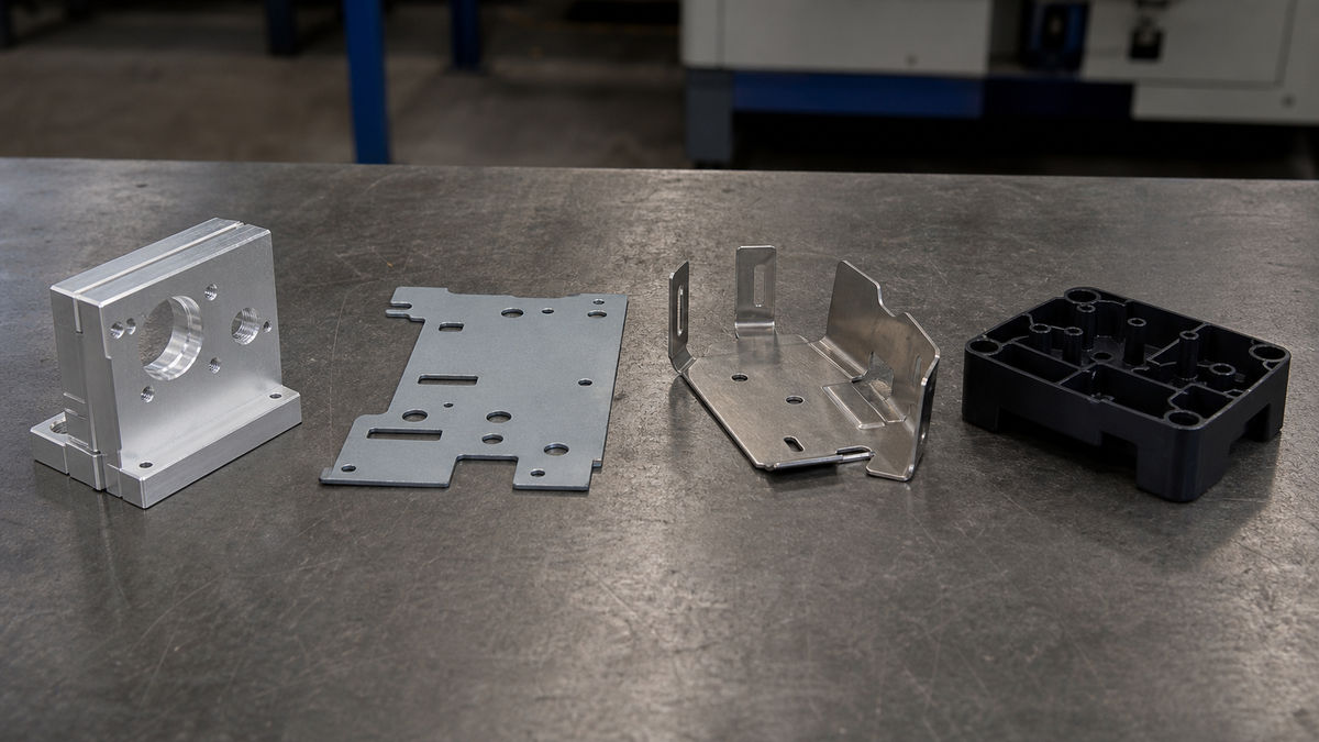
The confusion starts when a buyer uses a process name loosely. CNC turret punching and CNC punch press work use programmed punch tools on sheet metal1. Metal stamping uses dedicated dies to cut or form sheet metal. Sheet metal fabrication may include cutting, punching, bending, forming, welding, and finishing. Plastic injection molding uses a mold and polymer material. These processes have different rules for wall thickness, burr direction, springback, draft, tooling risk, finish, and approval.
| RFQ wording | Process meaning | Specification details the supplier needs |
|---|---|---|
| CNC machining | Material removal from solid stock | Machined datums, tolerances, material grade, finish, and inspection scope |
| CNC turret punching or CNC punch press | Programmed punching of sheet metal | Sheet thickness, flat pattern, punch features, burr direction, and forming notes |
| Metal stamping | Die-based cutting or forming | Material strip assumptions, forming direction, springback review, tooling intent, and volume context |
| Sheet metal fabrication | Cutting, bending, punching, welding, finishing, or assembly | Bend radii, bend direction, flat pattern, weld notes, finish, and inspection needs |
| Plastic injection molding | Mold-based polymer forming | Resin, draft, wall thickness, gate location assumptions, shrinkage review, and tooling intent |
If an RFQ uses CNC turret punching, CNC punch press, CNC-controlled stamping equipment, or metal stamping depending on the actual process, treat it as an ambiguous phrase, not a standard standalone process. Clarify whether the buyer means CNC turret punching, CNC punch press work, CNC-controlled stamping equipment, die stamping, or CNC machining of an aluminum part.
Which datums should control the aluminum part dimensions?
Use functional datums that match how the part locates, assembles, and will be inspected. A stable datum scheme helps the supplier understand feature relationships, reduce tolerance stack-up, plan workholding, and avoid quoting from scattered dimensions that do not reflect the part function.
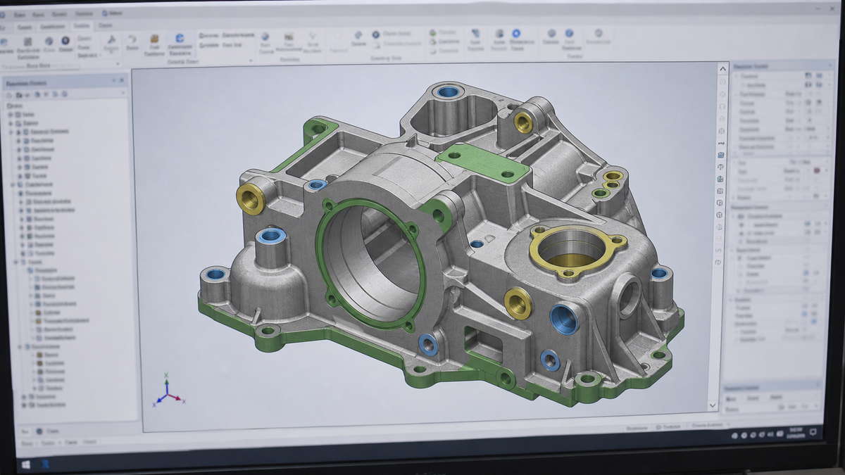
A datum is a reference used to locate dimensions and control the relationship between features. In a quote package, datums tell the supplier what matters first. A machined plate may use a mounting face and two locating holes. A turned part may use its center axis and a shoulder face. A housing may use a mating face, bore, or hole pattern.
The weak drawing habit is dimensioning from whichever edge is convenient in the current view. That can create chained dimensions where each feature depends on the previous one. Chained dimensions may describe shape, but they often hide the feature that actually controls assembly fit. A baseline or datum-based approach2 is clearer when hole positions, mating faces, bore locations, or aligned surfaces are functional.
Scenario: A rectangular aluminum bracket has four clearance holes and one dowel hole. If every hole is dimensioned from a different outside edge, the supplier may not know whether the outside profile or the hole pattern controls assembly. If the dowel hole and mounting face define location, those should become the controlling references.
Use these checks before sending the drawing:
- Start with overall envelope dimensions so stock size and machining envelope are understandable.
- Define the primary functional face, bore, axis, or hole pattern.
- Dimension critical features from functional datums instead of unrelated cosmetic edges.
- Call out repeated features once where practical, with quantity and pattern information.
- Remove redundant dimensions that create two possible acceptance conditions.
Should the model or drawing define the datum scheme?
The 3D model helps the supplier see geometry. The controlled 2D drawing should define datums, tolerances, notes, and inspection intent. If the model and drawing disagree, the RFQ should state which document governs.
Which dimensions need critical tolerances and which can use general tolerances?
Use general tolerances for ordinary non-critical features and reserve tighter tolerances for functional interfaces. For many non-critical aluminum CNC machined features, a general range around ±0.10 mm to ±0.13 mm can be a practical quoting baseline, but it remains supplier- and geometry-dependent.

A useful quoting drawing separates precision from ordinary geometry. Applying one tight tolerance to the whole part can increase machining time, inspection time, toolpath planning, and supplier risk without improving function. Leaving a true interface under-defined creates the opposite problem: the quote looks simple, but the part may not assemble or seal as intended.
A general tolerance note belongs in the title block or drawing notes. Where appropriate, the drawing may reference ISO 27683 or another suitable drawing standard, but the supplier still needs feature-level intent. Explicit tolerances should be reserved for dimensions that affect fit, sealing, alignment, motion, or approval.
| Feature or dimension | Better tolerance treatment | Practical quoting consequence |
|---|---|---|
| Bearing bore | Explicit size tolerance and inspection expectation | Drives tool choice, finishing pass, and measurement method |
| Sealing face | Local flatness, finish, or size requirement when needed | Affects finishing strategy and acceptance checks |
| Dowel hole | Controlled location or fit requirement when functional | Protects repeatable assembly alignment |
| Mating face | Size, flatness, or parallelism only where needed | Keeps assembly control separate from cosmetic faces |
| Clearance pocket | General tolerance if non-functional | Avoids pricing relief geometry as a precision feature |
| Cosmetic edge | General tolerance plus edge break if needed | Separates appearance from functional control |
Example: A cover plate may need precise dowel hole location and a controlled sealing face, while the outside profile and non-contact pockets can remain under general tolerance. That tells the supplier where setup care and inspection time belong.
When should GD&T enter the discussion?
If the real requirement is position, flatness, perpendicularity, parallelism, coaxiality, or profile, a size tolerance alone may not control the function. Use geometric controls only where they clarify acceptance and inspection.
Are wall thicknesses and pocket depths realistic for aluminum machining?
Wall thickness, pocket depth, and cavity width should be reviewed before quoting because they affect chatter, distortion, tool deflection, chip evacuation, and cycle time. If thin walls or deep pockets are functional, mark them clearly instead of letting the supplier guess their importance.
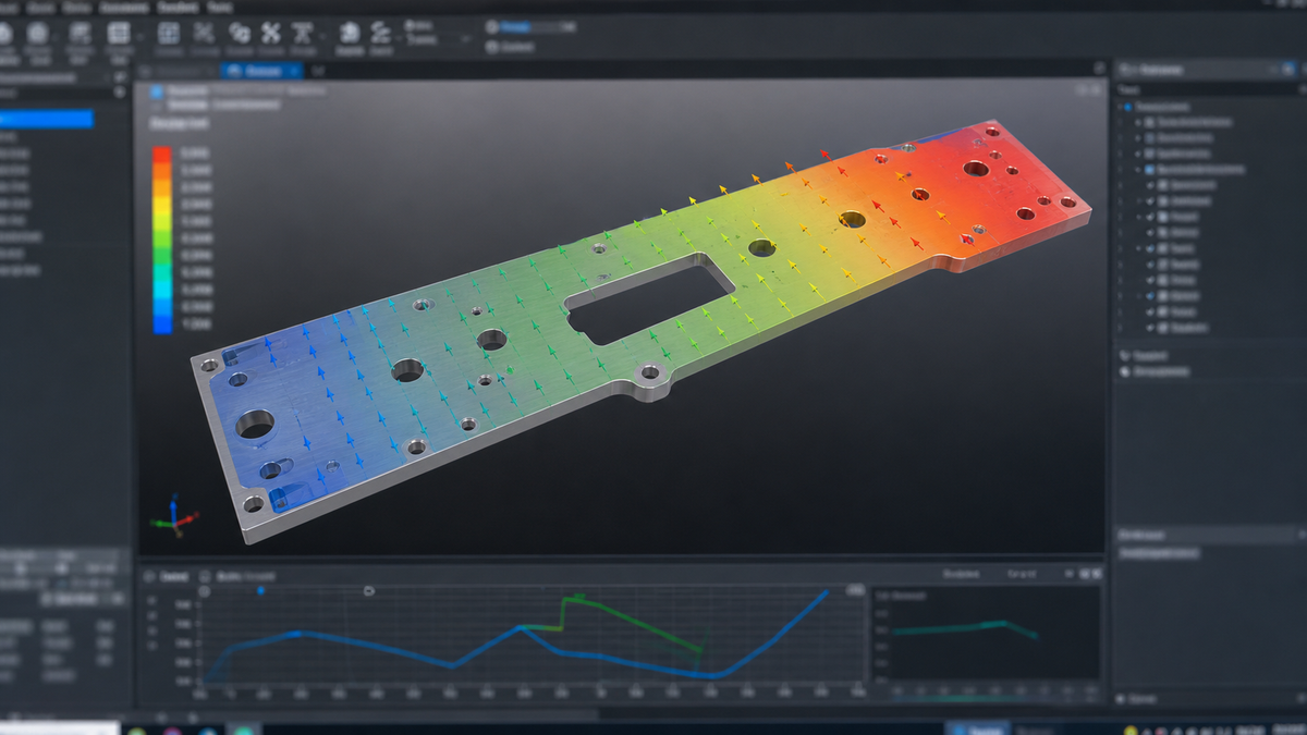
Aluminum machines well, but thin and deep geometry still changes the quote. A thin wall may deflect under clamping or cutting pressure. A deep pocket may require a longer cutter, lighter cutting, more passes, and closer attention to chip evacuation. A narrow cavity can force a smaller tool diameter, which reduces stiffness and may affect finish.
The supplied research identifies 0.8 mm as a recommended aluminum wall thickness reference, with 0.5 mm described as marginal and not advised. It also notes cavity depth around four times width4 as a practical design target. Treat these as review flags, not universal shop capability claims.
Scenario: A machined aluminum electronics cover has a deep internal pocket and a very thin outside wall. If the wall is only cosmetic, the buyer may be able to thicken it or relax the pocket depth. If the thin wall is needed for assembly clearance, the RFQ should say so. The supplier can then judge workholding, machining sequence, and inspection risk instead of guessing.
Useful checks before release:
- Dimension minimum wall thickness where thin sections affect fit, stiffness, or appearance.
- Show pocket depth and width clearly, not only the final model shape.
- Identify whether deep pockets are functional, weight-reduction features, or cosmetic relief.
- Avoid tight tolerances on thin walls unless the function justifies them.
- Ask for DFM feedback when wall thickness, pocket depth, and tolerance interact.
Why does this affect quoting?
The supplier estimates cutting time and manufacturing risk together. Thin and deep geometry can influence tool reach, chatter risk, fixture pressure, inspection repeatability, and whether the feature can be held consistently across the requested quantity.
Are internal radii and hole dimensions accessible to cutting tools?
Internal radii, hole diameters, and hole depths should be dimensioned with cutting tool access in mind. Sharp internal corners, blind features, and deep small holes can require smaller tools, longer tools, secondary cleanup, or more conservative machining assumptions during quotation.
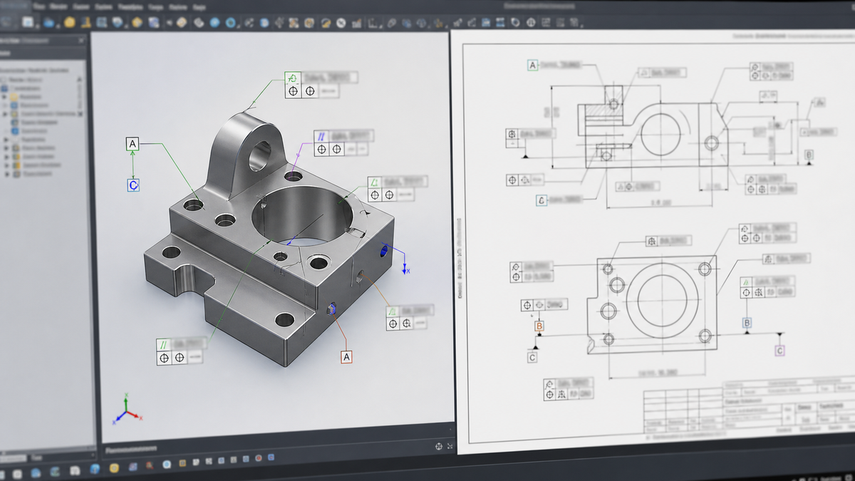
A milled internal corner cannot be perfectly sharp because the cutter has a radius. If the drawing implies sharp inside corners, the supplier has to decide whether a radius is acceptable, whether a smaller tool is needed, or whether secondary cleanup is required. That uncertainty can slow the quote or push it toward conservative assumptions.
The supplied research supports using internal vertical corner radii5 at least one-third of cavity depth as a common DFM rule. It also notes a recommended minimum hole diameter around 2.5 mm and practical hole depths from 4 times to 10 times diameter. These are design review references, not automatic guarantees for every feature.
| Feature | Drawing decision | Quoting consequence |
|---|---|---|
| Internal pocket corner | Specify an actual radius instead of implying a sharp corner | Allows a realistic cutter size and avoids unnecessary small-tool cleanup |
| Deep cavity corner | Review radius against cavity depth | Small tools in deep pockets increase deflection and cycle time |
| Blind hole | Show diameter, depth, bottom condition, and thread depth if threaded | Reduces assumptions around drilling, tapping, and inspection |
| Deep small hole | State whether full depth is functional | Helps the supplier judge drilling risk and tool reach |
| Counterbore or countersink | Dimension diameter, depth, and angle where needed | Prevents missing secondary features in the quote |
Example: A pocket drawn with square internal corners may look clean in CAD, but the machined part will normally include a cutter radius. If the mating part needs clearance in that corner, the drawing should show a relief feature or acceptable radius.
Should every radius be tightly controlled?
No. Control radii only where fit, tool access, stress, sealing, or appearance requires it. Ordinary cutter radii can often stay under general notes when they do not affect function.
Can the part be dimensioned to reduce setup changes?
Dimension the part so the supplier can see which features are controlled from the same setup and which require repositioning, indexing, or multi-axis access. Setup count affects alignment risk, fixture planning, inspection time, cost, and delivery assumptions.

A setup is one way of holding and orienting the workpiece while machining a group of features. Features made in one setup are usually easier to control relative to each other than features made after the part is flipped, reclamped, or indexed. That matters when the drawing has tight face-to-bore6, top-to-side, or hole-pattern relationships.
The buyer does not need to design the fixture. The drawing should simply reveal which relationships are important. If a bore on one face must align with a slot on another face, define that relationship with the right datums, dimensions, or GD&T. If a side feature is only a clearance notch, do not let it look as important as a datum bore.
Scenario: A small aluminum housing has a front bearing bore, a top mounting hole pattern, and side cable slots. If only the bearing bore and top hole pattern control assembly, the drawing should make that relationship clear. The side slots may not need the same positional control. Without that distinction, the supplier may quote more setup and inspection risk than the part needs.
Setup-sensitive details to flag:
- Features located on opposite sides of the part.
- Tight relationships between a bore and a face.
- Long hole patterns across broad plates.
- Off-axis holes or angled features.
- Deep pockets that restrict tool access.
- Features that may require indexing or 5-axis access.
- True position requirements across multiple faces.
Does fewer setups always mean better quoting?
Not always. Some parts need multiple setups to make the geometry correctly. The goal is to avoid unnecessary repositioning and to identify which cross-setup relationships truly need close control.
Could aluminum clamping or cutting behavior affect the quoted dimensions?
Yes. Aluminum sections that are thin, long, unsupported, or cosmetic can move under clamping and cutting pressure. The RFQ should identify delicate areas, no-clamp surfaces, visible faces, and finish-critical regions so the supplier can plan workholding and inspection before pricing.
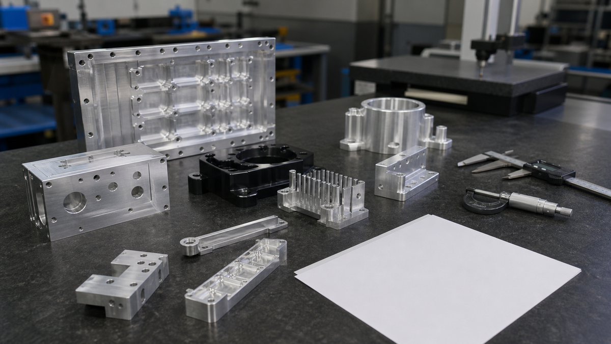
Aluminum is often selected because it machines efficiently, but it is still sensitive to how it is held and cut. Thin walls can flex. Long overhangs can vibrate. Delicate faces can mark under clamping. Adhesive behavior7 at the cutting edge can affect finish, burr formation, and dimensional consistency if chip control is poor.
This is where dimensioning and process planning meet. A drawing that shows only final geometry may not reveal that a surface must remain cosmetic, that a thin rib cannot be clamped, or that a long unsupported feature controls alignment. The supplier may then quote assumptions that do not match the buyer's acceptance criteria.
Common specification mistake: The drawing calls a thin wall critical but does not say whether the inside face, outside face, or wall thickness is the functional requirement. The supplier is left to decide what to protect during machining and inspection. A better drawing identifies the controlled surface, the relevant datum, and the expected inspection method.
For clamping-sensitive aluminum features, define:
- Minimum wall thickness where it affects fit or stiffness.
- Long cantilevered or unsupported sections.
- No-clamp surfaces or visible cosmetic faces.
- Sealing, sliding, or bearing surfaces that need protected finish.
- Burr-sensitive edges and deburring expectations.
- Whether dimensions apply before or after anodizing, plating, polishing, or other finishing.
Avoid prescribing feeds, speeds, coolant, or detailed cutting parameters unless there is a controlled manufacturing reason. A stronger RFQ explains the functional risk and lets the supplier choose practical workholding, cutting, chip control, and inspection.
Where should finish, threads, chamfers, and secondary operations be specified?
Specify finish, threads, chamfers, edge breaks, coating, masking, and secondary operations directly on the drawing where they apply. These details affect tooling, passes, handling, inspection, and acceptance, so they should not be left as assumptions in the model.
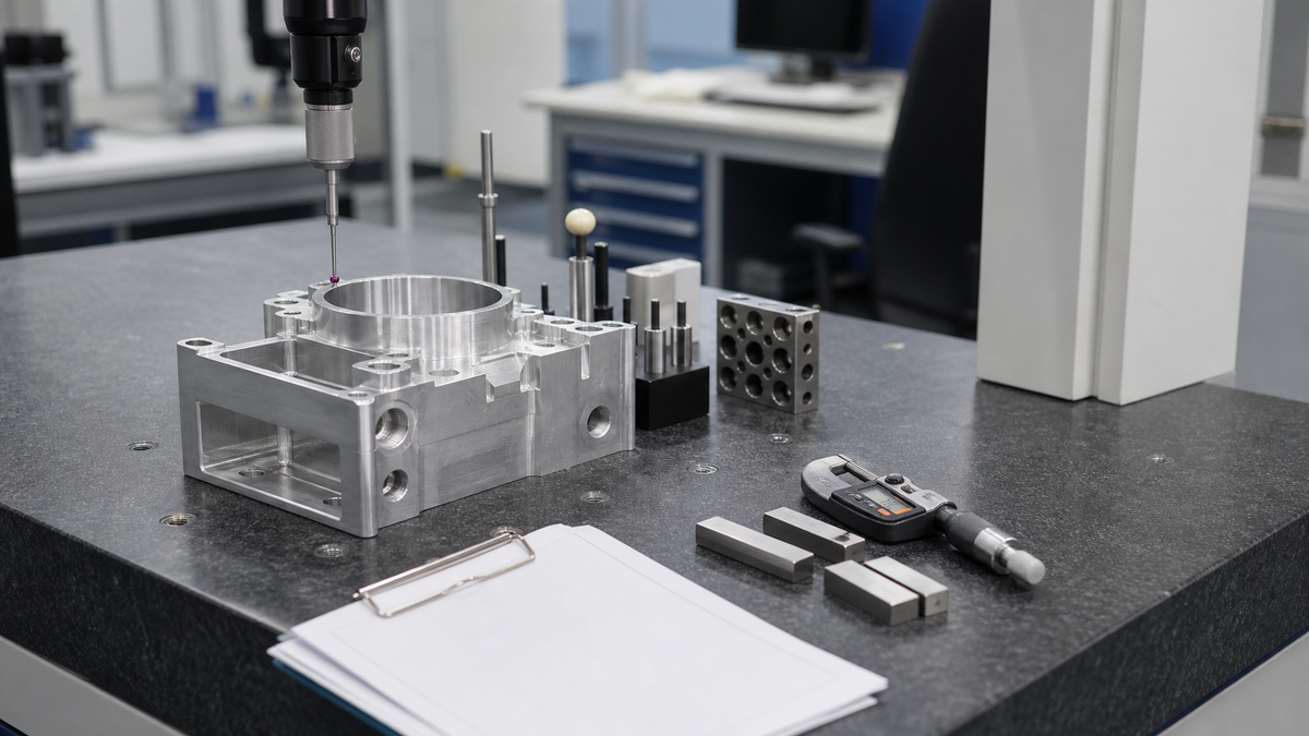
Many quote gaps come from details that look small in CAD but become separate manufacturing steps. A thread is not just a hole. A chamfer is not just an edge. A surface finish note may require a different toolpath strategy, extra finishing pass, polishing, or documented roughness inspection. Anodizing, bead blasting, plating, masking, laser marking, and deburring can also change handling and approval.
Localize these requirements. If one sealing face needs a controlled Ra value, call out that face. If all external edges need a light edge break, state it clearly. If a threaded hole has a functional minimum thread depth, dimension it. If anodizing or plating could affect a fit, state whether the dimension applies before or after finishing because finish buildup8 can change the acceptance condition.
Practical specification checks:
- Thread callouts should include thread size, depth, and whether the hole is blind or through.
- Chamfers should show size and angle when they affect fit, assembly, or appearance.
- Edge breaks should distinguish burr removal from a controlled chamfer.
- Surface finish should be assigned to functional or cosmetic areas, not automatically to the entire part.
- Anodizing, hard anodize, chromate conversion, bead blasting, plating, polishing, laser marking, assembly, or pressure testing should be listed only when required.
- Masking requirements should identify surfaces that must remain uncoated or protected.
Example: A blanket fine-finish note on every surface can make the supplier quote slower finishing passes and broader inspection even if only one sliding face needs controlled roughness. A localized note gives the supplier a more accurate machining and inspection basis.
What information must be included before requesting the CNC machining quote?
A complete CNC machining RFQ should include the 3D model, controlled 2D drawing, aluminum grade and condition, quantity, production intent, critical tolerances, finish, inspection requirements, revision level, and delivery expectations. Missing information forces suppliers to quote assumptions instead of the actual requirement.
The final RFQ should connect every dimensioning decision to the commercial request. A supplier cannot price only the shape. The quote depends on material sourcing, setup strategy, tooling, machining time, finish, inspection evidence, documentation, revision control, and whether the order is for prototype, pilot, or production release.
Use the 3D model to communicate complete geometry. Use the controlled 2D drawing to define specifications that the model may not communicate reliably: units, datums, tolerances, GD&T, threads, chamfers, finish, notes, inspection, and revision. If the model and drawing disagree, state which document controls before asking for price.
RFQ and approval checklist:
- 3D CAD model in an agreed file format.
- Controlled 2D drawing with active revision.
- Units, part name, drawing number, and title block notes.
- Aluminum grade and temper or condition.
- Quantity for the immediate quote.
- Prototype, pilot, or production intent.
- Estimated annual usage if known.
- Critical tolerances and general tolerance note.
- Functional, assembly, and non-critical feature identification.
- GD&T requirements and datums if feature relationships matter.
- Surface finish values and finish locations.
- Threads, chamfers, edge breaks, and burr expectations.
- Secondary operations such as anodizing, bead blasting, plating, masking, marking, assembly, or pressure testing when applicable.
- Inspection requirements such as first article inspection9, dimensional report, roughness readings, CMM report, material documentation, sampling, or selected full inspection.
- Delivery expectations and whether partial shipments are acceptable.
What should be checked before approving the quote?
Confirm that the supplier's assumptions match the drawing revision, material, tolerance level, finish scope, inspection method, quantity, and production intent. If the quote excludes a critical operation or assumes standard tolerances where the drawing needs tighter control, resolve that before purchase order release.
For a practical quoting recommendation, send the 3D model, controlled 2D drawing, aluminum grade and condition, quantity, prototype or production intent, critical tolerances, surface finish, inspection expectations, revision level, and delivery needs. Add notes for any feature that affects setup, tooling, finish, or approval.
References
-
What is a Turret Punch Press Machine and How Does It Work? - A turret punch press is a type of CNC (Computer Numerically Controlled) machine used to process sheet metal by punching holes, slots, or shapes ... ↩
-
Tolerance Stack Up – Chain vs Baseline Dimensioning - GD&T Basics - The GD&T method is more precise than baseline dimensioning because it references perfect tolerance zones from functional datum features, not a ... ↩
-
ISO 2768 Tolerance Standards for CNC Machining - JLCCNC - It consists of two parts: ISO 2768-1 and ISO 2768-2. ISO 2768-1 specifies general tolerances for linear and angular dimensions of workpieces. ↩
-
How to design parts for CNC machining | Protolabs Network - Cavities and pockets. Illustration of cavities and pockets. Recommended cavity depth: 4 times cavity width. ↩
-
CNC Machining Design Guidelines - Premium Parts - The recommended vertical corner radii for inner edges is 1/3 times the cavity depth or higher. This will allows for a better quality surface finish. If you need ... ↩
-
GD&T for CNC Machining: CNC Machine Tolerance Guide - uneed - GD&T defines tolerance zones relative to datums so that machining setup, CNC programming, and inspection alignment evaluate the same geometric requirement. ↩
-
CNC Milling Surface Finish: Optimize Aluminum Alloys - Aluminum is relatively soft and highly ductile. It tends to adhere to cutting tools. This adhesion causes built-up edge (BUE) and degrades the ... ↩
-
How Anodizing Affects Dimensions | Build-Up vs Penetration - Learn how anodizing changes aluminum part dimensions, including the critical difference between build-up and penetration for Type I, Type II, and Type III ... ↩
-
A Guide to First Article Inspection (FAI) - 1factory - every First Article Inspection report requires a dimensional record. Most require a Gage ID against each measurement. And a subset further requires a ... ↩