
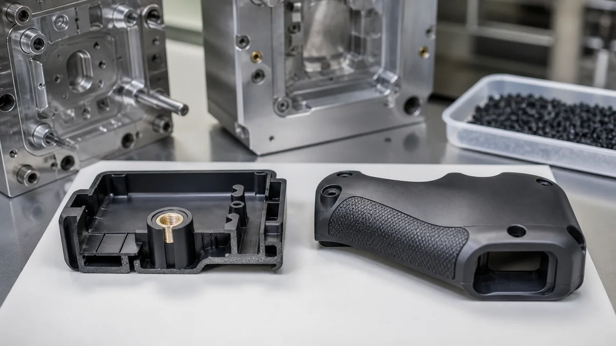
Insert molding and overmolding both combine materials through plastic injection molding, but they solve different design problems. Insert molding captures a preformed component inside molded plastic. Overmolding adds a second plastic or elastomer layer to an existing substrate.
The better route depends on the function of the added element, the loads carried by its interface, and the required production sequence. Material compatibility, retention geometry, critical dimensions, tooling, annual volume, inspection, and eliminated assembly work all influence the decision.
Begin with the required function rather than a preferred process name. From there, translate that function into material, geometry, tooling, acceptance, and RFQ requirements.
Does the Part Need an Embedded Insert or a Second Molded Layer?
Choose insert molding when plastic must permanently capture a preformed component such as threaded hardware, a contact, or a wire. Choose overmolding when a molded substrate needs a second plastic or elastomer layer for grip, sealing, cushioning, vibration damping, or visual contrast.
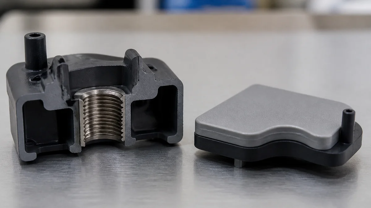
The first distinction is what exists before the main molding operation. In insert molding, a separately made component is positioned inside the mold before plastic is injected around it. The insert may be metal, ceramic, or preformed plastic. Its geometry, orientation, and retention features become part of the mold and loading plan.
Overmolding starts with an existing substrate. A second material is molded over selected areas through another step or shot. The substrate may move between molds or remain within a coordinated multi-shot arrangement. A common configuration is a rigid plastic substrate with a softer TPE or TPU layer, but the specified material pair still needs compatibility review.
| Specification question | Insert molding | Overmolding |
|---|---|---|
| What exists before the operation? | A separately sourced insert | A molded substrate |
| What does injection add? | Plastic around the insert | A second plastic or elastomer layer |
| Typical design purpose | Hardware or electrical integration | Grip, sealing, cushioning, or appearance |
| Main interface concern | Insert position and retention | Bonding and mechanical interlock |
| Production detail to disclose | Insert loading method | Second-shot or transfer method |
Do not select the process from appearance alone. Plastic surrounding metal hardware may indicate insert molding, whereas a soft region on a rigid housing may indicate overmolding. The controlled drawing1 should show material boundaries, identify the pre-existing component, and define the sequence when more than one molding stage is involved.
Is the Added Element Structural, Electrical, Sealing, or User-Facing?
Use the added element's dominant function as the process filter. Structural fastening, load retention, and electrical integration generally point toward insert molding, while grip, sealing, cushioning, vibration damping, and user-facing color or texture generally point toward overmolding.
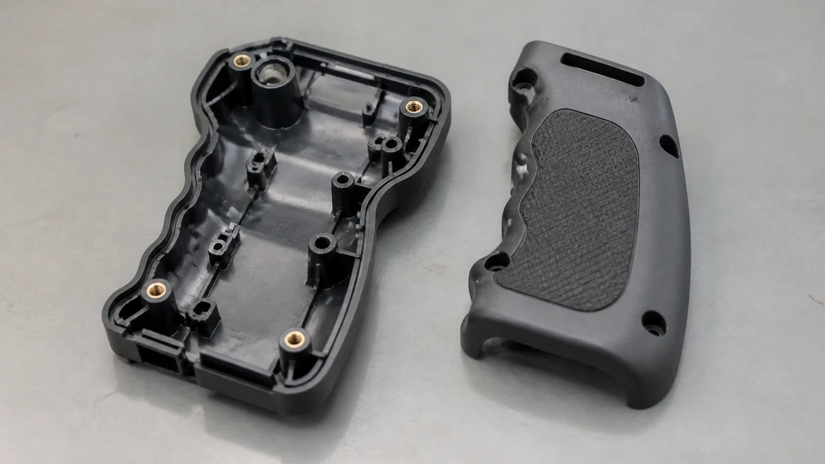
A useful specification starts with a verb: retain, conduct, seal, cushion, grip, or identify. That verb tells the supplier what the added element must accomplish and prevents a cosmetic feature from being quoted as a structural interface, or a loaded interface from being treated as decoration.
Insert molding may fit when the design must:
- Carry assembly torque through threaded hardware.
- Resist pull-out or rotation under service loads.
- Locate a pin, bushing, magnet, terminal, contact, or wire.
- Integrate a component that cannot be formed from the molding resin.
Overmolding may fit when the second material must:
- Improve handling through a soft-touch region.
- Create a sealing surface on a rigid substrate.
- Add localized cushioning or vibration damping.
- Define a contrasting user-facing or cosmetic zone.
One product can contain both kinds of function. The specification should therefore assign requirements by interface instead of forcing the complete assembly into one label.
Scenario: A handheld housing needs threaded attachment points and a softer gripping area. Treat the hardware as an insert-retention problem and the grip as a substrate-to-overmold interface2. Define torque or pull-out intent for the hardware separately from resin grade, coverage, bond behavior, and cosmetic expectations for the grip. The supplier can then assess whether the two functions require separate tools, sequential molding operations, or another assembly strategy.
Will the Selected Materials Form a Reliable Interface?
Specify every material at the interface and define whether retention must come from chemical bonding, mechanical geometry, or both. Do not assume that two named resins will adhere simply because each can be injection molded; the supplier must review the actual substrate and overmold combination.
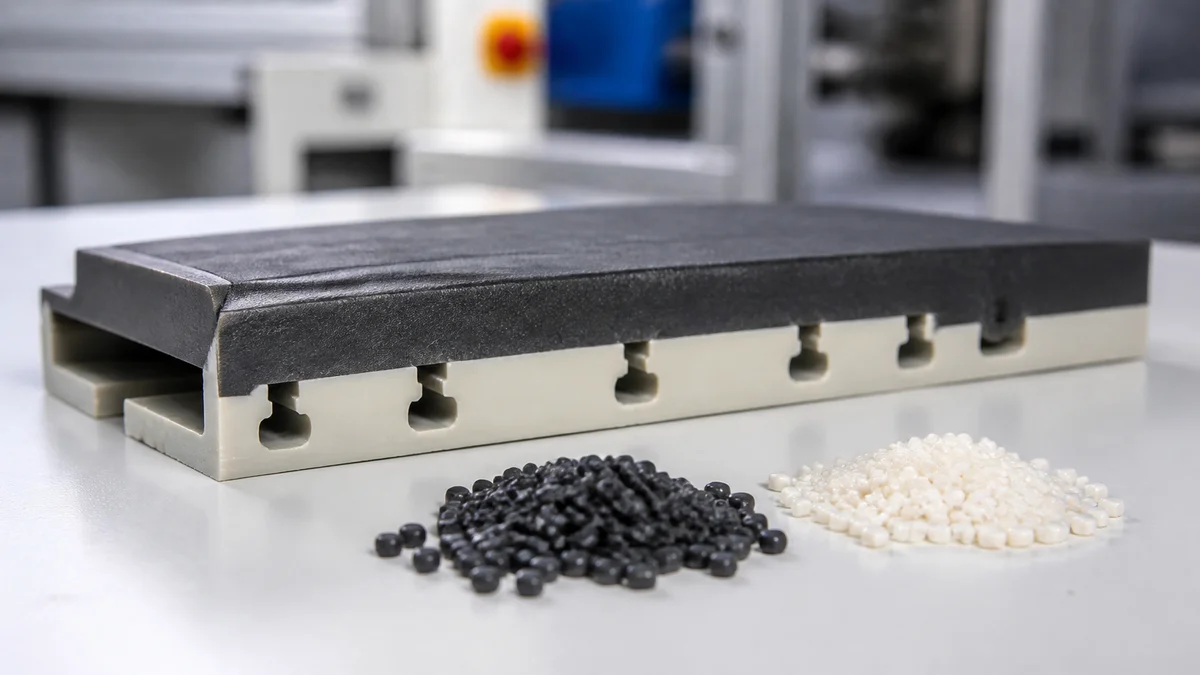
Material compatibility is central to overmolding because the second material must remain attached to the substrate during use. TPE or TPU may be applied over a rigid plastic, but those broad material families do not establish a reliable bond by themselves. Identify the exact substrate resin and overmold resin, including approved grades when known.
| Interface strategy | Retention principle | Drawing or RFQ input |
|---|---|---|
| Chemical bond | Compatible substrate and overmold materials | Exact resin grades and required interface behavior |
| Mechanical interlock3 | Geometry physically locks the materials | Openings, undercuts, wraparound zones, or other retention features |
| Combined interface | Material compatibility plus locking geometry | Resin pair, interface geometry, and acceptance method |
Insert molding requires a related but different review. The insert may be metal, ceramic, or preformed plastic, and the molding resin must fill around it without losing the required position or final geometry. Chemical adhesion may be secondary; knurls, grooves, undercuts, or texture may carry the service load.
Is “good adhesion” an adequate specification?
No. It does not define where the interface matters or how acceptance will be judged. If bond strength or peel resistance controls function, identify the interface, load direction, test intent, and sample-approval requirement. For a seal, show the sealing zone and mating condition. If retention is entirely mechanical, say so explicitly. That prevents the quotation from relying on an assumed resin-to-resin bond.
Can the Insert Retention Geometry Resist the Applied Loads?
Design insert retention around the actual torque, pull-out, vibration, and repeated-assembly demands. Knurls, grooves, undercuts, or surface texture can provide a mechanical lock, but the RFQ must also control insert orientation, anti-rotation behavior, loading direction, and relevant acceptance requirements.

An insert should not be treated as a smooth object that plastic merely surrounds. Its geometry must give the molded resin a path to resist the applied load. Knurls or texture can improve engagement, grooves can resist axial movement, and undercuts can create a more positive lock. The appropriate feature depends on how the insert is loaded.
For DFM review, document:
- Direction and purpose of the service load.
- Whether torque, pull-out, vibration, or repeated assembly governs.
- Required orientation and exposed insert length.
- Whether rotation would cause functional failure.
- Pull-out or anti-rotation acceptance criteria, when required.
- Insert material, complete geometry, and thermal mass.
- Critical wall thickness4 and dimensions around the insert.
Thermal mass deserves attention because an insert can influence local fill, cooling, shrinkage, and warpage. Nearby sealing lands or cosmetic faces may also respond differently from ordinary molded surfaces. Supply the actual insert definition rather than only a simplified cavity model.
Example: A threaded insert intended for repeated assembly may need axial retention and anti-rotation control. A groove could address pull-out while a knurled or non-round region could address torque. This is a teaching example, not a universal geometry prescription. Resin grade, insert form, surrounding walls, loading sequence, and inspection method still need joint review.
A frequent specification mistake is defining the internal thread but omitting the load transferred into the surrounding plastic. Thread geometry alone does not tell the molder how the insert must be retained.
Which Tooling and Part-Loading Strategy Fits Production?
Compare quotations by the complete tooling and handling sequence. Insert molding may use manual or automated loading into one mold, while overmolding may use separate molds, substrate transfer, two shots, or a 2K arrangement. These alternatives carry different tooling, handling, and production assumptions.

The process name does not fully describe the production system. Two suppliers can quote insert molding or overmolding while assuming different tooling stacks, loading methods, and transfer responsibilities. Require each quotation to explain how the insert or substrate reaches its molding position.
| Production route | Operating sequence | Specification details to confirm |
|---|---|---|
| Manual insert loading | Insert is placed before injection | Orientation, presentation, loading scope, and verification |
| Automated insert loading | Equipment presents and loads the insert | Insert geometry consistency, feeding method, and automation scope |
| Separate overmolding tools | Substrate is molded, moved, and molded again | Transfer, cooling, alignment, storage, and handling responsibility |
| Multi-shot or 2K arrangement | Materials are molded in a coordinated tool sequence | Substrate indexing, tool scope, and complete cycle definition |
Manual loading may suit one production plan, while automation may deserve review when repeat demand and insert presentation support it. There is no defensible universal volume breakpoint because insert shape, geometry, batch pattern, inspection scope, and supplier workflow all affect the choice.
For overmolding, clarify whether the substrate transfers immediately, cools before the second stage, or waits between separate operations. The answer can affect alignment, contamination exposure, work-in-process, and approval planning.
Ask suppliers to separate mold scope, insert or substrate sourcing, loading, transfer, automation, sample approval, and recurring production. Without this quotation breakdown5, a lower tooling figure may simply omit part of the required handling system.
How Should Complete Cycle Time and Throughput Be Compared?
Compare the complete production cycle, not injection time alone. Insert molding includes insert sourcing, presentation, orientation, loading, molding, and ejection; overmolding may add substrate molding, cooling, transfer, positioning, a second shot, and further handling before inspection and packaging.
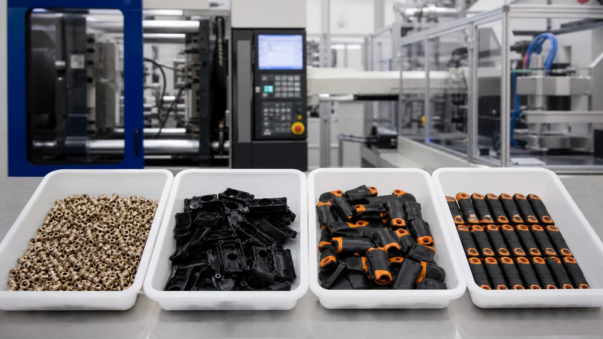
Calling insert molding a one-shot process can obscure work outside the injection stage. The insert must arrive in the specified condition, be oriented correctly, enter the tool, remain located during injection, and be verified after molding. Manual and automated loading create different timing and control assumptions.
Overmolding adds another material stage. Depending on the tooling plan, the substrate may cool, move to another cavity or mold, and be repositioned before the second material is injected. Transfer between stages can become a throughput constraint even when both shots are individually straightforward.
Review the complete sequence:
- Insert or substrate preparation.
- Presentation, loading, transfer, and orientation.
- Injection and cooling for every molding stage.
- Ejection and molded-part handling.
- Inspection or scheduled sample checks.
- Packaging and any work-in-process storage.
Annual demand does not tell the whole story. Include batch size, release pattern, production intent, design maturity, and expected revisions. An annual forecast split across irregular small releases creates a different operating requirement from predictable scheduled batches.
The practical question is whether the second overmolding stage delivers a necessary seal, grip, cushioning layer, vibration response, or cosmetic boundary. For insert molding, ask whether embedding the component removes enough downstream installation and handling to justify the loading method. Suppliers should document their full-cycle assumptions6 rather than offer an unsupported comparison based only on machine cycle time.
Which Final Molded Features Need Tolerance and Inspection Control?
Control the dimensions and interface characteristics that determine fit, sealing, alignment, electrical isolation, bonding, pull-out, or anti-rotation after molding. Do not apply blanket precision to the complete part; define the final measurement condition, inspection scope, and sample-approval evidence for critical features.
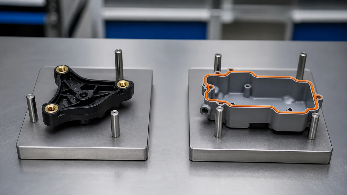
Acceptance should refer to the final delivered condition. Insert position, resin shrinkage, cooling, substrate transfer, and the second molding stage can alter feature relationships. A dimension measured on the loose insert or first-shot substrate does not prove that the completed part meets its functional requirement.
Localize control by function:
- Insert location: position, orientation, exposed length, or alignment with a mating feature.
- Assembly: dimensions that determine final fit or tolerance stack-up7 with other components.
- Sealing: overmold coverage, sealing-zone geometry, and alignment with the mating surface.
- Electrical function: contact location, separation, and isolation requirements.
- Retention: pull-out or anti-rotation acceptance when those loads govern.
- Bonding: defined peel or bond behavior at selected interfaces.
- Cosmetics: viewing surfaces, material boundaries, and acceptable surface variation.
The 2D drawing should distinguish critical tolerances from ordinary molded geometry and state whether dimensions apply after every molding stage. Specify the inspection method or functional check where it matters, the characteristics requiring recorded results, and whether approval applies to initial samples, production sampling, or both. Do not assume reports or full inspection are automatically included.
What should sample approval represent?
Approval should use the intended material pair, insert, tooling sequence, and final measurement condition. If a seal or bond requires functional evaluation, define it before quotation. If pull-out or rotation controls insert acceptance, identify the load direction and applicable feature. This keeps inspection focused on design risk rather than producing measurements that do not establish function.
How Can Delamination and Insert Movement Be Prevented Before Tooling?
Reduce failure risk before tooling by reviewing the actual materials, bonding mechanism, retention geometry, insert orientation, thermal mass, sealing zones, cosmetic surfaces, and final critical dimensions together. Overmolding is vulnerable to weak interfaces; insert molding is vulnerable to movement and inadequate mechanical retention.
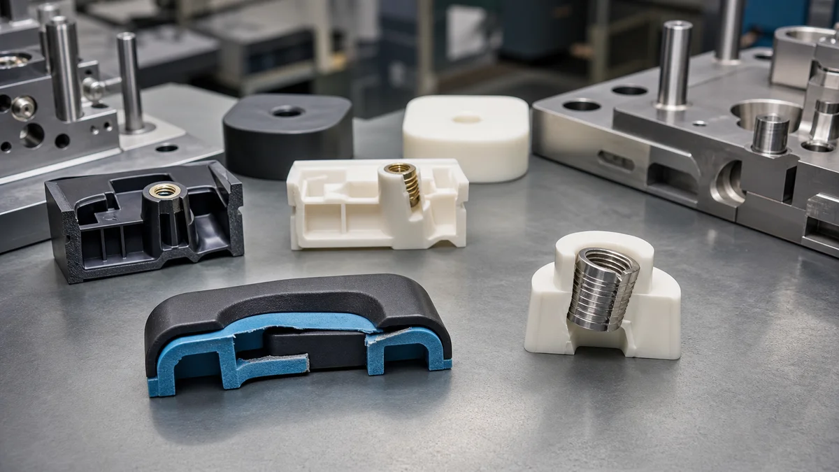
Delamination and insert movement occur at different interfaces, but both belong in DFM review before tooling release. For overmolding, the supplier needs to know whether attachment depends on chemical compatibility, mechanical interlock, or both. For insert molding, the review must establish how the insert is located and how the surrounding plastic carries the service load.
| Failure risk | Missing specification | Pre-tooling action |
|---|---|---|
| Weak overmold bond | Resin pair or bonding principle is undefined | Name both grades and define functional acceptance where required |
| Delamination at an edge | Coverage and interlock geometry are incomplete | Show material boundaries, edge conditions, and retention features |
| Insert displacement | Orientation and loading controls are unclear | Define insert datums, exposed position, and loading method |
| Insert rotation or pull-out | Service-load direction is absent | State the governing load and acceptance criterion |
| Local shrinkage or warpage | Thermal mass and nearby walls are ignored | Supply the insert definition and mark critical surrounding geometry |
Scenario: A seal appears on the model as a colored band around a rigid housing, but the RFQ names neither resin grade nor bonding method. Color communicates coverage, not interface performance. Before tooling, define the substrate, overmold grade, sealing zone, any mechanical lock, gate-sensitive cosmetic areas, and sample-approval method.
Another common mistake is approving an insert-molded concept from nominal insert position alone. The review also needs retention features, orientation method, surrounding wall thickness, and critical post-molding relationships. Gate location8, flow around the insert, and cooling remain supplier DFM subjects rather than details to leave invisible until mold construction.
Which Process Has the Lower Total Delivered-Assembly Cost?
Compare equivalent delivered assemblies rather than mold price or molded piece price alone. Include insert sourcing, tooling complexity, loading, substrate transfer, cycle steps, inspection, and the adhesives, fasteners, press-fitting, soldering, welding, or other assembly operations that the molding route may eliminate.
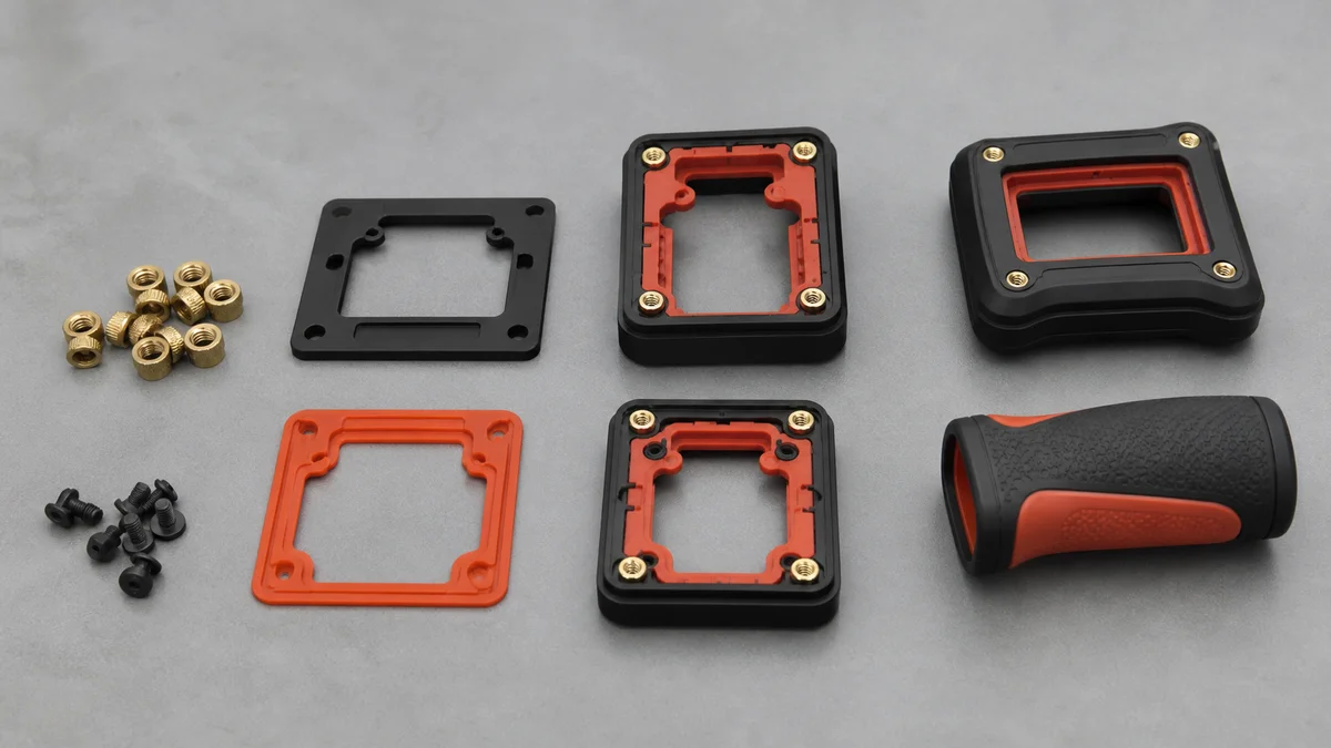
Neither process has a universal cost advantage. Insert molding may use one injection shot, but it adds insert purchasing, presentation, loading, and position control. Overmolding may eliminate a separately installed grip, seal, adhesive, or fastened layer, while adding another resin, molding stage, and transfer requirement.
Use the same commercial boundary for every quotation:
| Cost element | Insert molding scope | Overmolding scope |
|---|---|---|
| Tooling | Mold plus insert-location and retention provisions | Separate molds, two shots, transfer, or 2K tooling |
| Purchased content | Preformed inserts | Substrate and second resin |
| Handling | Insert presentation, loading, and verification | Cooling, transfer, positioning, and work-in-process |
| Acceptance | Insert position, pull-out, or anti-rotation | Coverage, interface behavior, seal, or cosmetics |
| Potentially removed work | Press-fitting, soldering, welding, or hardware installation | Adhesive bonding, fastening, or separate seal installation |
Describe every eliminated operation accurately. Embedding an electrical contact may remove later placement or joining, but the quotation still needs the contact specification and loading responsibility. An overmolded seal may remove a separately installed component, but material, interface, and approval requirements remain.
Quantity, annual demand, batch size, design maturity, inspection level, and revision risk also affect total program cost9. Instead of asking for a universal break-even volume, request separate entries for tooling, samples, recurring production, purchased content, secondary operations, and inspection. This reveals whether an apparent saving comes from assembly elimination or omitted scope.
Are the Manufacturing Processes Named Correctly in the RFQ?
Name insert molding and overmolding as plastic injection molding routes. Keep them distinct from CNC machining, CNC turret punching, CNC punch press work, sheet metal fabrication, and metal stamping. If an RFQ says “CNC turret punching, CNC punch press, CNC-controlled stamping equipment, or metal stamping depending on the actual process,” clarify the intended equipment and process before quotation.

Process names establish different material forms, tooling assumptions, geometry constraints, and acceptance risks. Using them interchangeably can route an RFQ to the wrong supplier or produce quotations based on incompatible scopes.
| Process | Operating principle | Starting material |
|---|---|---|
| Insert molding | Plastic is injected around a preformed insert | Resin plus a metal, ceramic, or preformed plastic insert |
| Overmolding | A second plastic or elastomer is molded over a substrate | Molded substrate plus second resin |
| CNC machining | Cutting tools remove material from solid stock | Billet, bar, plate, or plastic stock |
| CNC turret punching or CNC punch press work | Programmed punch tools create sheet features | Sheet metal |
| Metal stamping | Dedicated dies cut or form material | Sheet or strip metal |
| Sheet metal fabrication | Cutting, punching, bending, welding, hardware insertion, and finishing may be combined | Sheet metal |
“CNC turret punching, CNC punch press, CNC-controlled stamping equipment, or metal stamping depending on the actual process” is not one standard process term. It may refer loosely to CNC turret punching, CNC punch press work, CNC-controlled stamping equipment, or general die stamping. Clarify the machine type, material form, feature type, and tooling intent before quotation.
Insert molding and overmolding both belong to plastic injection molding. Placing a metal insert inside plastic does not turn the molding operation into metal stamping. Similarly, CNC machining used to manufacture an insert is a separate upstream operation, not another name for insert molding.
An RFQ may include several operations, but their order should remain explicit: source or manufacture the insert, mold the plastic, complete approved secondary work, and inspect the final delivered condition.
What Information Belongs in an Insert Molding or Overmolding RFQ?
A useful RFQ combines controlled design files, exact materials, realistic demand, production intent, critical dimensions, interface requirements, inspection scope, revision level, and delivery expectations. Add process-specific information for insert loading and retention or for substrate-to-overmold bonding, sealing, and material coverage.

A complete package lets the supplier review the intended process instead of filling gaps with assumptions. Use the 3D model for full geometry and the controlled 2D drawing for critical dimensions, material boundaries, notes, surface requirements, and acceptance criteria. Identify the governing document if the files conflict.
Core RFQ and approval checklist10
- 3D model and controlled 2D drawing.
- Current revision level and governing document.
- Exact resin, approved grades, color, and additives where applicable.
- Quantity, batch expectations, annual demand, and production intent.
- Prototype, validation, launch, or repeat-production status.
- Critical tolerances, datums, and final measurement condition.
- Functional and cosmetic surface-finish requirements.
- Inspection method, sampling, reporting, and sample-approval expectations.
- Delivery expectations and known design-change risk.
- Required final assembly state and packaging scope.
For insert molding, add:
- Insert drawing, material, geometry, orientation, and sourcing responsibility.
- Knurls, grooves, undercuts, texture, or other retention features.
- Manual or automated loading expectations, if prescribed.
- Pull-out, torque, anti-rotation, vibration, or assembly requirements.
- Electrical contact, isolation, or exposed-position requirements.
- Insert thermal mass and critical surrounding plastic geometry.
For overmolding, add:
- Substrate and overmold resin grades.
- Material coverage and boundary definition.
- Chemical bond, mechanical interlock, or combined interface intent.
- Bond, peel, sealing, grip, or cushioning requirements where functional.
- Cosmetic zones and sample-approval criteria.
- Whether the part remains serviceable or becomes intentionally non-disassemblable.
Ask the supplier to identify tooling scope, loading or transfer method, inspection assumptions, and exclusions. That response makes competing quotations easier to compare.
For a process recommendation, sample plan, or quotation, send the 3D model, controlled 2D drawing, material grades, quantity, prototype or production intent, critical tolerances, surface finish, inspection expectations, revision level, and delivery requirements. Include insert loading and retention details or the proposed substrate-to-overmold interface.
References
-
Overmolding and Insert Molding Design Guide - A guide to two-material molding and bonding options with plastics, elastomers, and metal inserts. Overmolding is an injection molding process that allows an ... ↩
-
Overmolding: Multi-Material Injection Molding Complete Guide - Complete guide to overmolding: process, materials, design considerations, and applications. industry standard for TPE and elastomer overmolds is 1–3 mm. ... ↩
-
Overmolding Materials Guide: Material Bond Compatibility - This article will further discuss how overmolding works, common overmolding materials used, DFM (Design for Manufacturing) considerations, and ... ↩
-
Insert Molding Design Guide: A Detailed Guideline - Wall Thickness of the Mold. Wall thickness influences major features ... It safeguards the products against “torque out” and “pull out” defects. ↩
-
Two-Shot Injection Molding vs Overmolding - Learn the differences between two-shot injection molding and overmolding. Discover which process is best for your manufacturing needs. ↩
-
Overmolding and Insert Molding: From Prototyping to ... - Overmolding is a multi-step injection molding process where two or more components are molded over top of one another. Overmolding is sometimes referred to as ... ↩
-
Injection Molding Tolerance: What ±0.05 mm Actually Costs - Polymer shrinks as it cools, typically 0.4% to 2.0% depending on resin. On a 300 mm part, shrinkage variation alone can exceed ±0.5 mm before any process drift. ↩
-
A Complete Guide to Overmolding - Process & Design Guide - Gate Location – Plastic needs to get from the molding machine into the desired area of the part. When the plastic enters the part (at the gate), a small mark ... ↩
-
What's the Difference between Overmolding and Insert Molding? - Lower production volumes favor insert molding because tooling costs ... However, overmolding can reduce total expenses by eliminating assembly. ↩
-
Injection Molding RFQ Checklist for Accurate Quotes - HingTung - A 2D drawing is still important because the 3D model may not show critical tolerances, datums, cosmetic areas, or inspection notes. Include ... ↩