
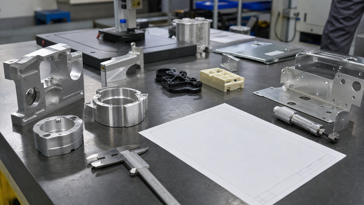
Aluminum CNC machining is often chosen for prototypes and low-volume production because it can produce real metal parts without a dedicated die or mold. The advantage is flexibility, but the RFQ still needs discipline. A supplier cannot price the right plan from a vague request for an aluminum part.
The machining route depends on production intent, material grade, geometry, tolerance level, surface finish, inspection method, and revision stability. A prototype built for learning should not carry the same assumptions as a repeat production release.
The planning questions below move from process definition to RFQ readiness, so the buyer can separate useful precision from unnecessary cost and give the supplier enough evidence to quote the work clearly.
Should the Job Be Specified as a Prototype, Pilot Run, or Low-Volume Production Order?
Specify the job stage before quoting because prototype learning, functional validation, pilot builds, and repeat low-volume orders require different assumptions for setup, toolpath efficiency, inspection scope, finishing, material purchasing, revision control, and schedule. This keeps.
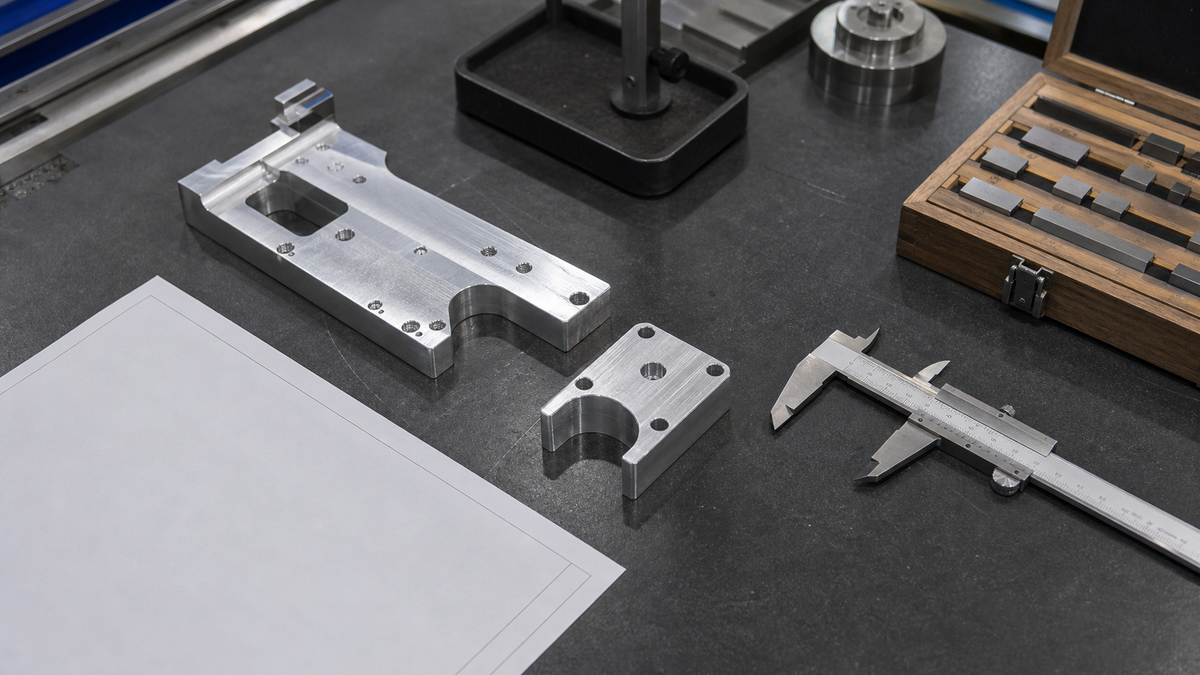
A prototype is usually built to answer a design question. Does the geometry fit? Do the mounting holes line up? Is the material appropriate for the assembly? In that stage, flexibility may matter more than optimizing every machining minute.
A pilot run starts to test repeatability. The drawing, inspection method, finish notes, and revision control begin to matter more because the same decisions may carry into later builds. A low-volume production order needs even clearer acceptance criteria, especially when the supplier must repeat setups, purchase material, or coordinate finishing.
| Order stage | Main purpose | Specification focus | Quoting risk if unclear |
|---|---|---|---|
| Prototype | Learn from the first physical parts | Fit, geometry, basic function, revision flexibility | Supplier may overbuild a learning part |
| Functional validation | Check selected performance or assembly needs | Critical interfaces, material, finish, inspection | Functional features may be underdefined |
| Pilot run | Confirm repeat build assumptions | Setup, revision control, inspection method | Approval steps may be missed |
| Low-volume production | Supply repeatable usable parts | Batch consistency, finishing, documentation, schedule | Purchasing and inspection effort may be underquoted |
Example: a bracket for a bench fit check may not need final cosmetic finishing or dimensional reporting. The same bracket for a pilot assembly may need controlled hole position, defined edge breaks, and a released drawing revision.
The RFQ should state the production intent1 in plain language, not only the quantity. Quantity tells the supplier how many parts to make; intent tells the supplier how seriously to treat fixturing, documentation, inspection, and repeatability.
Is CNC Machining the Right Process, or Is the RFQ Actually Asking for Sheet Metal, Stamping, or Molding?
Confirm the process before quoting because CNC machining, CNC turret punching, metal stamping, sheet metal fabrication, and plastic injection molding use different materials, tooling, geometry rules, tolerance behavior, and cost drivers. This keeps the specification.

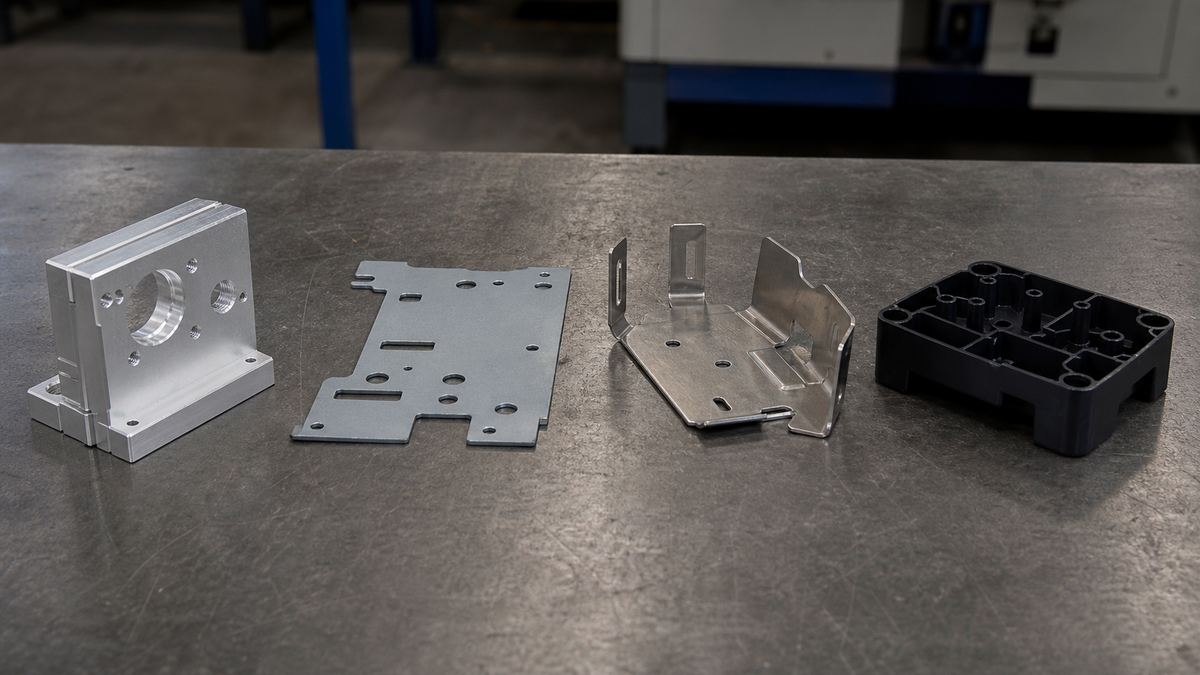
CNC machining removes material from aluminum stock by milling, turning, drilling, boring, reaming, and related operations. It fits parts with machined pockets, bores, threads, faces, slots, and precision interfaces cut from bar, plate, billet, or similar stock.
That is not the same as sheet metal work. CNC turret punching or CNC punch press work uses programmed punch tools2 on sheet metal. Metal stamping uses dedicated dies to cut or form sheet metal, and the design must account for tooling, bend behavior, burr direction, and springback. Sheet metal fabrication is broader and may include cutting, bending, punching, welding, hardware insertion, and finishing. Plastic injection molding uses a mold for polymer parts, with separate concerns such as resin, draft, gate location, ribs, bosses, and wall thickness.
| RFQ term | Manufacturing route | Specification details to clarify |
|---|---|---|
| CNC machining | Material removal from solid aluminum stock | Datums, tolerances, tool access, finish, inspection |
| CNC turret punching | Programmed punching of sheet metal | Sheet thickness, hole forms, burr direction, bends |
| Metal stamping | Die-based sheet metal cutting or forming | Tooling intent, springback, annual volume, part development risk |
| Sheet metal fabrication | Cut, bend, punch, weld, finish sheet components | Flat pattern, bend radius, hardware, finish side |
| Plastic injection molding | Molded polymer production | Resin, draft, gate location, wall thickness, tooling plan |
If someone writes CNC turret punching, CNC punch press, CNC-controlled stamping equipment, or metal stamping depending on the actual process, treat it as an ambiguous phrase. It may mean CNC turret punching, CNC punch press work, CNC-controlled stamping equipment, or general metal stamping. Clarify the process before comparing quotes.
Mistake: comparing a machined aluminum block with a stamped bracket as if they are interchangeable. Both may be metal parts, but the geometry, tooling, tolerance stack-up, and inspection method are different.
Which Aluminum Grade, Temper, and Material Condition Should Be Quoted?
Name the aluminum grade, temper, and material condition in the RFQ because material choice affects machinability, toolpath assumptions, distortion risk, finishing response, sourcing, documentation, and whether wrought stock machining is the correct route. This keeps.
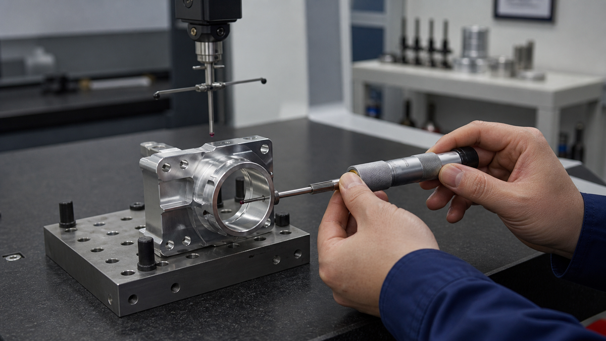
Saying only aluminum leaves too much open. Different grades and tempers can behave differently during machining, finishing, and inspection. The supplier may need to plan cutting data, workholding, stock allowance, and finishing assumptions around the actual material.
For prototypes, the material may be selected for availability, machinability, or similarity to the intended production grade. For low-volume production, the material becomes part of the controlled specification. If the part requires a particular wrought aluminum alloy and temper3, machining from bar, plate, or billet may be the right route. A casting alloy or molded plastic should not be treated as equivalent.
Useful RFQ details include:
- Aluminum grade and temper or condition.
- Whether the buyer or supplier provides the material.
- Whether material documentation is required.
- Whether stress relief or dimensional stability concerns should be discussed.
- Whether finishing response matters, including anodizing or chromate conversion.
- Whether dimensions apply before or after finishing.
Example: if the buyer expects an anodized visible surface, the material and finish expectations should be reviewed together. The supplier can then consider sourcing, machining marks, masking, and inspection after finishing instead of treating the finish as a late add-on.
Material also affects quote discipline. If the RFQ says aluminum only, one supplier may quote from a common shop assumption while the buyer expects a specific grade, temper, or documentation package. That gap can cause re-quoting, schedule changes, or acceptance disputes.
Which Deep Features, Narrow Cavities, or Hole Depths Could Drive Machining Risk?
Identify deep pockets, deep holes, narrow cavities, and high aspect-ratio features before quoting because they can increase tool deflection, vibration, chip evacuation difficulty, cycle time, special tooling needs, and inspection uncertainty. This keeps the specification.
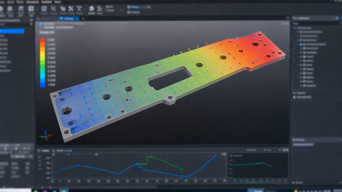
Tool access is one of the first geometry checks in aluminum CNC machining. A broad shallow pocket is usually easier to machine than a narrow deep pocket. A short hole is usually easier to drill and inspect than a deep hole. A feature hidden behind a wall may require longer tools, additional setups, or a different machining sequence.
The supplied research supports two practical design checks: keep cutter length-to-diameter ratio under 4:14 where possible, and treat hole depths above 6 times diameter as more difficult. These are not universal manufacturing limits, but they are useful warning signs during design review.
Which features should be called out?
Call out deep features when they affect assembly, sealing, airflow, weight reduction, fastener engagement, or cosmetic acceptance. If a deep pocket is only for weight reduction, the supplier may be able to suggest a wider radius, shallower cut, or less demanding finish. If the feature is functional, the drawing should say so.
Geometry that deserves review includes:
- Deep pockets with small internal corner radii.
- Blind holes with tight depth or thread requirements.
- Narrow slots that require long, slender tools.
- Thin walls beside deep cuts.
- Cavities with poor chip evacuation paths.
- Internal details that are not clear in standard views.
Mistake: giving every pocket wall the same finish and tolerance. That can force slow cutting and inspection on geometry that does not affect fit. A better drawing separates functional faces from clearance pockets and lightening geometry.
Can the Part Be Designed to Reduce Setups and Use Standard Tooling?
Design for fewer setups and standard tools where possible because every repositioning step, unusual hole size, custom cutter assumption, and difficult access direction can affect repeatability, inspection effort, quoting confidence, and low-volume cost. This keeps.
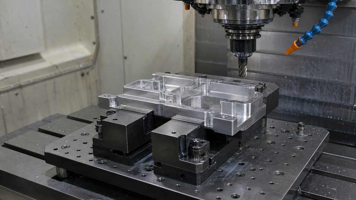
Setup count matters because the part has to be held, referenced, cut, released, repositioned if needed, and inspected. Features made in one setup are generally easier to control relative to each other than features machined after several re-clamps.
For an early aluminum prototype, a supplier may use a simple setup to get a first part made. For low-volume production, repeated setup time and repeated inspection effort become more important. The design should make it clear which surfaces are datums, which relationships are critical, and which features can remain non-critical.
| Design choice | Manufacturing consequence | Better RFQ instruction |
|---|---|---|
| Features reached from one main side | Reduces repositioning and relationship risk | Identify primary datum face and critical hole pattern |
| Cross-side features | May require indexing or re-clamping | Mark which top-to-side or face-to-bore relationships matter |
| Nonstandard holes or threads | May require special tools or extra checks | Use standard sizes unless function requires otherwise |
| Very small internal radii | May require smaller tools and longer cutting time | Increase radii where assembly allows |
| Repeat parts in a stable revision | May support batching or multi-part workholding | State quantity, revision stability, and expected repeat demand |
Example: a machined plate with critical holes referenced from one datum face and one datum edge is easier to quote than a plate where chained dimensions travel around the drawing. Chained dimensions can create tolerance stack-up5 and make the real assembly relationship harder to inspect.
Standard tooling does not mean low quality. It means the design avoids special operations where the function does not need them, leaving precision effort for the real interfaces.
Which Features Need Tight Tolerances and Which Can Use General Tolerances?
Separate critical, assembly, and non-critical features because a blanket tight tolerance can make an aluminum part harder to machine, inspect, and quote without improving function, fit, or acceptance confidence. This keeps the specification tied to.
Tolerance should follow function. Bearing bores, sealing faces, dowel holes, press-fit areas, mating surfaces, and alignment features often need closer control than cosmetic edges, lightening cuts, clearance pockets, or non-contact surfaces. Treating the whole part as equally precise usually adds machining and inspection effort without improving the part.
For many non-critical aluminum CNC machined features, a general tolerance around ±0.10 mm to ±0.13 mm can be a practical quoting baseline when tighter control is not required. This remains supplier- and geometry-dependent, not a universal rule. General tolerances should normally appear in the drawing notes or title block, or by referencing an appropriate standard such as ISO 27686 where applicable.
How should the drawing separate tolerance levels?
Use a general tolerance note for ordinary dimensions, then mark critical features individually. A tiered tolerance plan helps the supplier see where to spend machining and inspection effort.
Practical tolerance grouping:
- Functional features: bearing bores, sealing surfaces, datum faces, press fits.
- Assembly features: dowel holes, fastener patterns, alignment shoulders, mating faces.
- Non-critical features: cosmetic chamfers, clearance pockets, lightening cuts, external edges.
- Review features: thin walls, broad plates, long spans, or surfaces affected by finishing.
Mistake: applying a very tight default tolerance to every dimension because the part is important. Tight tolerance should be tied to a specific function. If selected features require tolerances below about ±0.05 mm, the discussion should include fixturing, tool wear control, thermal stability, and inspection method.
Where Should GD&T Be Used Instead of Only Tight Size Tolerances?
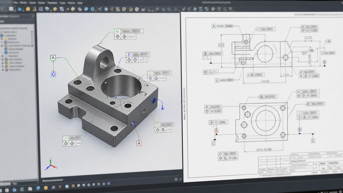
Use GD&T when the functional issue is the relationship between features, not only their size, because flatness, perpendicularity, parallelism, true position, coaxiality, or profile may define assembly performance more clearly. This keeps the specification tied.

Some aluminum parts are difficult to specify with size tolerances alone. A housing may need two bores aligned. A cover plate may need a hole pattern located from a datum edge. A sealing face may need flatness more than a tighter overall length. A multi-setup part may need a feature on one side controlled relative to a feature on another side.
GD&T can communicate those relationships directly, but it should not be scattered across a drawing as decoration. It needs clear datums, realistic controls, and an inspection expectation. Otherwise, the supplier may need to guess how the requirement will be verified.
Use GD&T when the requirement involves:
- Position of a hole pattern from functional datums.
- Flatness of a sealing or mounting surface.
- Perpendicularity between a bore and a face.
- Parallelism between mating surfaces.
- Coaxiality or alignment between related cylindrical features.
- Profile control for a shaped surface where size dimensions are not enough.
A true position callout7 can be more useful than tightening every X and Y dimension in a hole pattern, provided the datums reflect how the part fits or is inspected. The same logic applies to flatness on broad plates and perpendicularity on face-to-bore relationships.
GD&T should also be connected to setup planning. Features machined in one setup are generally easier to control relative to each other. Cross-setup relationships, broad plates, deep pockets, and long hole patterns need careful review before tight geometric controls are applied.
What Inspection Evidence Should Match the Tolerance Requirement?
Define inspection evidence with the tolerance requirement because first article checks, in-process inspection, final reports, CMM measurement, sampling, or selected full inspection can change quote assumptions and approval timing. This keeps the specification tied to.

A tolerance is incomplete if nobody knows how it will be checked. Some dimensions can be verified with hand tools. Others, especially form, position, flatness, or tight hole patterns, may require a more structured inspection method. The RFQ should identify critical dimensions and state what evidence is expected at delivery.
Inspection scope can affect cost and schedule because it uses measurement time, documentation time, and review effort. The supplier may quote differently if the buyer requires first article inspection8, in-process checks, final dimensional reporting, CMM measurement, sampling, or selected 100 percent inspection for critical features.
What should be defined before quote approval?
Clarify the inspection scope before comparing suppliers:
- Which dimensions are critical to function or assembly.
- Whether the first part, first lot, every shipment, or every revision needs inspection evidence.
- Whether dimensional reports are required for all features or only selected features.
- Whether CMM measurement is expected for geometric controls.
- Whether material documentation or a certificate of conformance is required.
- Whether inspection should occur before or after anodizing, coating, or assembly.
Mistake: requesting tight tolerances but saying nothing about inspection. One supplier may quote simple final checks while another includes detailed reporting. The prices may look different because the responsibilities are different.
For low-volume production, inspection planning should also follow revision control. If the part changes after prototype approval, the RFQ should say whether the new revision needs a fresh first article or only selected checks.
What Chip Control and Surface Requirements Should Be Discussed Before Quoting?
Discuss chip control and surface expectations early because aluminum machining can be affected by chip evacuation, built-up edge, recutting, chatter, tool length, coolant or air blast strategy, and required finish level. This keeps the specification.
The buyer usually does not need to prescribe feeds, speeds, coolant settings, or toolpath details. Those decisions belong with the supplier unless there is a specific engineering reason. The buyer should define what each surface must do.
Aluminum machining can suffer when chips are not cleared effectively. Recutting chips, built-up edge, poor surface finish, chatter, and dimensional drift can appear when tool engagement, chip evacuation, tool length, or cutting strategy is poorly matched to the geometry and material. Deep pockets, narrow slots, and blind cavities deserve attention because chips may have fewer exit paths.
The useful specification question is not how fast the tool will cut. It is which surfaces require which result.
Functional surface categories may include:
- Sealing surfaces that need a defined finish and flatness relationship.
- Sliding or bearing-related surfaces where roughness may matter.
- Visible cosmetic faces where tool marks or handling marks are limited.
- Internal clearance pockets where finish is less important.
- Deburred edges that must avoid assembly interference or handling risk.
Example: a visible front face on an aluminum enclosure may need a different finishing pass than an internal pocket hidden after assembly. If both are marked with the same surface requirement, the supplier may machine and inspect more than the design needs.
Surface finish should also be coordinated with secondary operations. Bead blasting, anodizing, or masking can change appearance and acceptance expectations, so machining finish and final finish should not be specified in isolation.
Which Finish, Edge Break, Coating, or Secondary Operation Should Be Controlled?
Control finishing and secondary operations only where they affect function, appearance, assembly, or inspection because blanket requirements for finish, edge breaks, anodizing, masking, or marking can add unnecessary cost and lead time. This keeps the.
Machining does not end when the last cut is made. Aluminum parts may need deburring, edge breaks, chamfers, surface finish control, anodizing, hard anodize, chromate conversion, bead blasting, laser marking, masking, assembly, or another secondary operation. Each requirement should have a reason.
A functional surface may need a defined Ra value because it seals, slides, mates, or supports alignment. A cosmetic surface may need a visible finish expectation. A sharp edge may need an edge break because it affects handling or assembly. A coated part may need masking where electrical contact, grounding, sealing, or tight fit must remain uncoated.
RFQ finish details should cover:
- Which surfaces require specific finish values or cosmetic expectations.
- Whether dimensions apply before or after finishing.
- Which holes, threads, bores, or datum surfaces must be masked.
- Whether deburring is general or controlled by edge location.
- Whether burr direction matters for assembly or contact surfaces.
- Whether laser marking, assembly, or pressure testing is part of the quote.
Burr direction is worth clarifying when a machined edge meets a mating part, gasket, sliding surface, or handling surface. It is not enough to say deburr if one side must remain clean and the other side is less important.
Finish buildup9 can also affect acceptance. If anodizing, hard anodize, or another surface treatment changes a tight bore, thread, or mating face, the drawing should clarify whether the controlled dimension applies before or after finishing.
How Should Quantity, Revision Stability, and Schedule Shape the Machining Strategy?
Quantity, revision stability, and schedule should be stated together because one-off prototypes, pilot builds, and repeat low-volume orders can justify different fixturing, batching, inspection, material purchasing, and delivery assumptions. This keeps the specification tied to.
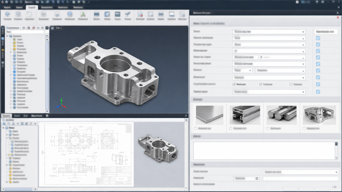
The same aluminum part can be quoted differently depending on whether the buyer needs one learning sample, a small pilot lot, or a repeat low-volume order. Quantity affects setup planning, but revision stability affects whether that setup investment makes sense. Schedule affects material purchasing, finishing coordination, inspection reporting, and whether partial shipments may help.
A supplier cannot infer future demand from a single line item. If the design is still changing, flexible programming and simpler fixturing may be more practical. If the design is released and repeat orders are likely, better workholding, batching, or multi-part machining may be worth discussing.
| RFQ information | Why it changes planning | What to state |
|---|---|---|
| Immediate quantity | Defines the first quoting scope | Prototype, pilot, or production quantity |
| Projected annual usage10 | Helps evaluate repeatability assumptions | Estimated demand if known |
| Revision stability | Affects setup and fixture decisions | Prototype revision, released drawing, or pending changes |
| Delivery expectation | Influences material, finishing, and inspection timing | Required date or priority option |
| Partial shipment need | May affect production sequencing | Whether split delivery is acceptable |
Scenario: a buyer asks for 20 machined aluminum housings but expects additional demand after testing. If the RFQ does not say that, the supplier may quote the first 20 as a short-run build instead of considering repeat setup efficiency or approval planning.
This does not require a volume guarantee. It simply tells the supplier whether the quote is for a one-time prototype, a bridge to low-volume production, or the first release of a repeat program.
What Complete RFQ Information Should Be Sent Before Aluminum CNC Machining Is Quoted?
Send a complete RFQ package before quoting so the supplier can evaluate geometry, material, quantity, production intent, tolerances, GD&T, finish, inspection, revision level, delivery needs, and any future process transition. This keeps the specification tied.
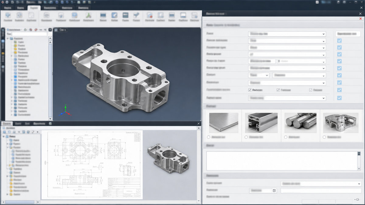
A strong RFQ reduces hidden assumptions. It does not need to overcontrol every feature, but it should give the supplier enough evidence to quote the manufacturing plan honestly.
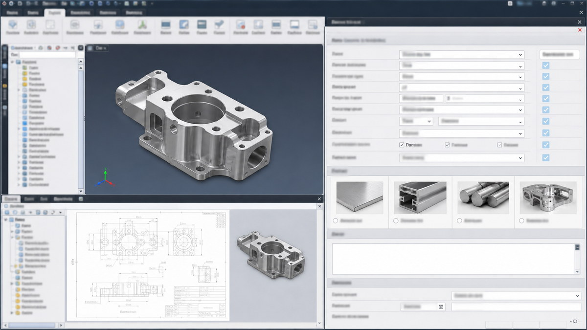
Use this RFQ checklist11 before requesting price or sample approval:
- 3D CAD model for geometry review and machining planning.
- Controlled 2D drawing for tolerances, units, notes, threads, finish, and inspection requirements.
- Active revision level and drawing number.
- Aluminum grade and temper or condition.
- Quantity for prototype, pilot, or low-volume production.
- Prototype or production intent.
- Critical tolerances and general tolerance note.
- GD&T requirements with clear datums where relationships matter.
- Surface finish, deburring, edge break, coating, masking, or marking requirements.
- Inspection requirements and delivery evidence.
- Material documentation requirements if applicable.
- Delivery expectations and partial shipment needs.
- Notes about future production route if tooling may be considered later.
Scenario: machined housing before tooling. A buyer may CNC machine an aluminum housing first, then later consider die casting or plastic injection molding after the design is validated. That early CNC housing should still be reviewed for wall thickness, corner radii, draft, fastening features, cosmetic surfaces, and critical machined interfaces. This is a teaching scenario, not a customer case.
If the part may later move to die casting, ask which features would still need CNC finishing after casting, such as sealing faces, bearing seats, datum surfaces, threads, or tight hole patterns. If it may later move to plastic injection molding, do not assume the machined aluminum design will transfer directly. Resin, draft, wall thickness, ribs, bosses, gates, and mold construction become separate design issues.
The final RFQ should make the current process clear: CNC machining from aluminum stock.
For a practical recommendation, sample plan, or quotation, send the 3D model, controlled 2D drawing, aluminum grade and temper, quantity, prototype or production intent, critical tolerances, surface finish, inspection expectations, revision level, and delivery needs. Include any future die casting, sheet metal, or plastic molding comparison.
References
-
CNC Machining RFQ Template Guide - uneed - prototype or production intent is stated; inspection requirements are included; delivery timing, packaging, and logistics assumptions are defined if relevant. ↩
-
CNC Turret Punch Guide: Process, DFM, Cost vs Laser - JLCCNC - CNC turret punching is a sheet metal fabrication process that produces holes, slots, cutouts, and formed features in flat sheet using a CNC- ... ↩
-
Aluminum and Aluminum Alloys Subject Guide - ASM International - Cold-worked aluminum is designated by various grades of the H temper, with higher second digits indicating increasing amounts of cold work (for example, the H1 ... ↩
-
How to design parts for CNC machining | Protolabs Network - End mill tools have a limited cutting length (typically 3–4 times their diameter). Tool deflection, chip evacuation and vibrations become more prominent when ... ↩
-
Tolerance Stack Up – Chain vs Baseline Dimensioning - GD&T Basics - When using chain dimensioning, the location tolerance of a given feature will be equal to the sum of the location tolerances of preceding ... ↩
-
ISO 2768 Tolerance Standards for CNC Machining - JLCCNC - ISO 2768-1 aims to simplify drawing indications and provides general tolerances categorized into four tolerance classes: fine (f), medium (m), ... ↩
-
True Position - Position Tolerance | GD&T Basics - True Position, or just Position as the ASME Y14.5 standard calls it, is defined as the total permissible variation that a feature can have from its “true” ... ↩
-
A Guide to First Article Inspection (FAI) - 1factory - A First Article Inspection (FAI) is a business process that determines whether the manufacturing process for a part is capable of consistently delivering parts ... ↩
-
How Anodizing Affects Dimensions | Build-Up vs Penetration - Learn how anodizing changes aluminum part dimensions, including the critical difference between build-up and penetration for Type I, Type II, and Type III ... ↩
-
Include Target Quantities and Annual Volumes in Your RFQ - Including target quantities and annual volumes in every RFQ ensures transparency between the customer and the supplier. This simple step leads ... ↩
-
CNC Machining RFQ Checklist: Get Faster, Accurate Quotes - 1) Send both the drawing and the 3D model (when available). Best combo: 2D drawing (PDF) with dimensions, tolerances, notes, revision, and date. ↩