
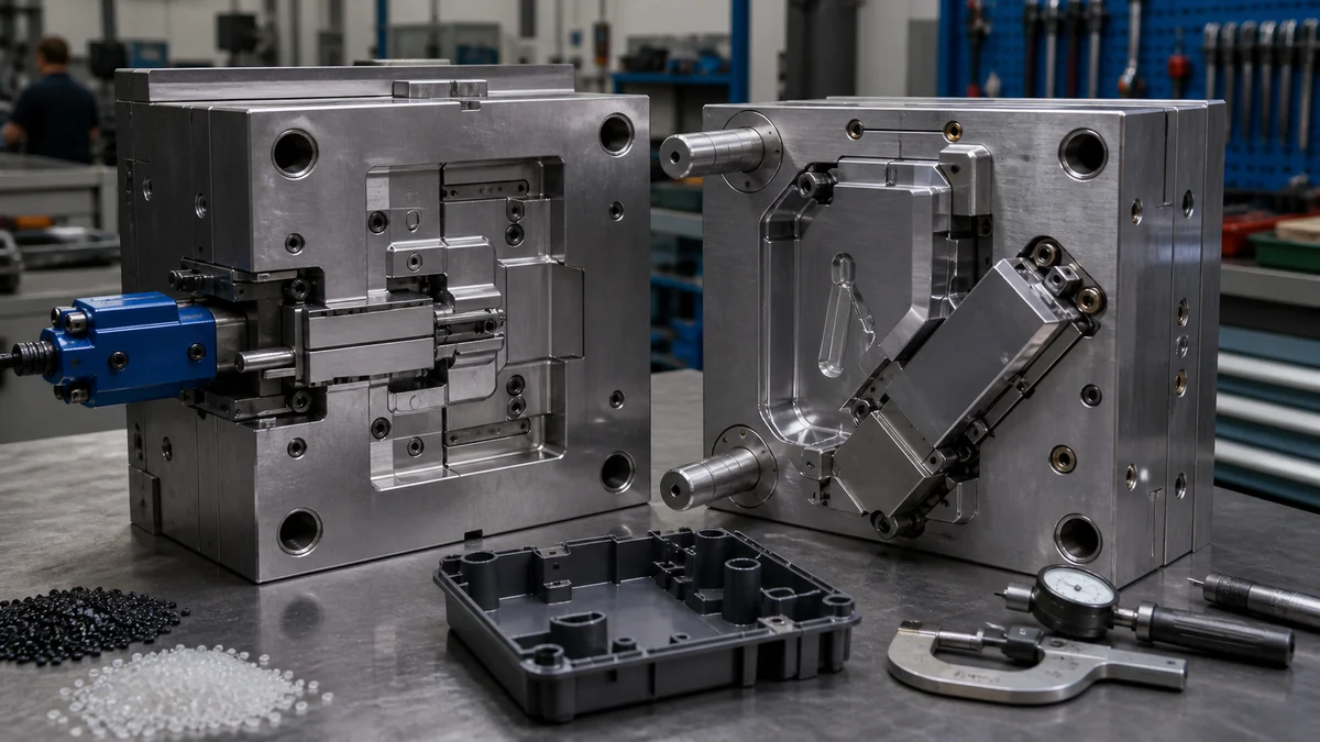
Undercuts can provide essential retention, clearance, sealing, or assembly functions, but they also prevent an injection molded part from releasing along a straight mold-opening path. If the feature remains, the tool may need a slide, lifter, collapsible core, unscrewing action, hand-loaded insert, or another specialized release mechanism.
The right solution begins with geometry and pull direction, not a preferred mechanism. Resin grade, wall thickness, draft, undercut depth, surface texture, critical tolerances, annual demand, cosmetic zones, and maintenance access can all change the mold concept.
Planning these details before quotation lets the toolmaker evaluate release motion, mechanism loading, ejection timing, cooling, inspection, and sample approval without filling specification gaps with assumptions.
How Should You Identify an Undercut from the Mold Pull Direction?
Establish the mold’s primary opening direction, then mark every feature that cannot release along that line. Treat side holes, hooks, clips, recesses, and internal overhangs as potential undercuts until orientation, draft, and ejection analysis confirms that the part can separate without another mold action.
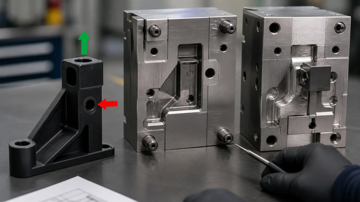
The pull direction is the path along which the core and cavity separate. A feature is an undercut when some part of its geometry remains mechanically trapped during that movement. Because orientation changes this relationship, review how the part sits in the mold before specifying a slide or lifter.
Build an undercut map during injection molding DFM1. For every candidate feature, record:
- Feature ID and location.
- External, internal, or rotational classification.
- Retention, clearance, sealing, cosmetic, or assembly function.
- Proposed pull direction and permitted alternative orientations.
- Undercut depth and required release direction.
- Nearby wall thickness, ribs, bosses, parting lines, and cosmetic surfaces.
- Acceptable witness lines, shutoff marks, and local draft changes.
- Permission to remove, open, split, or relocate the feature.
Reorienting the part may align a side hole or recess with mold opening and eliminate a side action. That change is not free, however. It can move the parting line, restrict gate location, alter which surfaces remain on the core, or reduce ejection support. Evaluate the complete molding layout rather than counting undercuts alone.
Example: A transverse hole in a molded bracket blocks release when its axis is perpendicular to mold opening. Rotating the bracket may align the hole with the pull direction, but the new orientation still needs adequate draft, practical gate access, stable ejection, and an acceptable parting line on visible surfaces.
A common specification mistake is directing the supplier to “mold as modeled” without defining release direction or feature function. That leaves a basic mold-architecture decision unresolved and makes quotations difficult to compare.
Should an Undercut Use a Slide or a Lifter?
Use a slide as the initial choice for an external undercut and a lifter as the initial choice for a smaller internal undercut. Confirm the choice by checking depth, direction, available mold space, required travel, ejector stroke, shutoffs, cooling, guidance, and maintenance access.
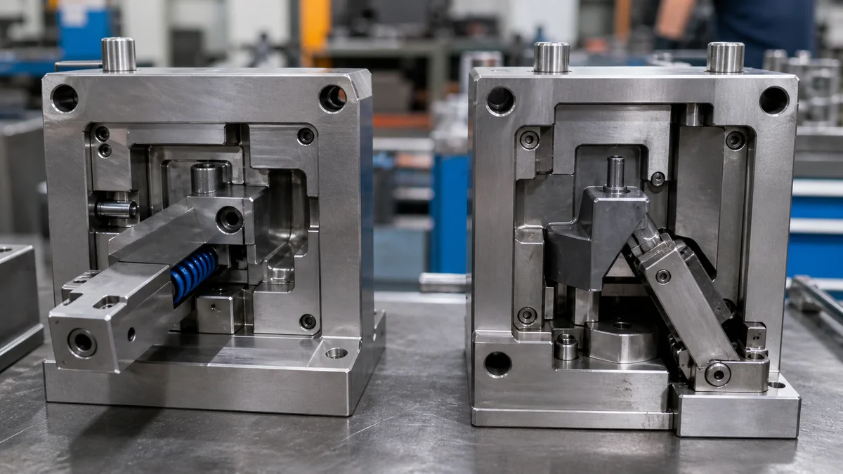
Slides and lifters both form geometry that the primary mold-opening motion cannot release, but their motion and loading differ. A slide retracts laterally before ejection. A lifter travels at an angle with the ejector system, combining outward part movement with sideways clearance.
| Specification factor | Slide review | Lifter review |
|---|---|---|
| Typical feature location | External undercut | Internal undercut |
| Common geometry | Side hole, outside recess, external hook | Internal snap, hook, rib, or local recess |
| Release motion | Lateral retraction before ejection | Angled travel with ejector stroke |
| Critical travel input | Undercut depth plus release clearance | Lateral travel produced by angle and stroke |
| Mold-design concerns | Locking, shutoffs, guidance, cooling | Guidance, bearing length, clearance, wear |
| Part-quality risk | Flash or mismatch at a worn shutoff | Dragging, sticking, flash, or distorted snap |
| Service consideration | Access to locking and sliding surfaces | Access to guides and wear surfaces |
This is a selection screen, not a universal side-action mold design rule2. The feature’s visible location does not prove that sufficient mold steel, travel, support, cooling, or service access exists for the proposed mechanism.
For either option, release travel must exceed nominal undercut depth by enough margin to prevent the molded surface from dragging. The toolmaker should determine that margin from resin shrinkage, surface texture, local draft, part stiffness, travel direction, and ejection behavior.
Do not specify a lifter merely because a feature is inside the part. A deep internal feature, restricted ejector stroke, long unsupported mechanism, or heavily loaded shutoff may require a different concept. Likewise, a small external detail might be opened to the parting line or redesigned instead of receiving a slide. Ask the supplier to show the mechanism envelope and complete motion before approving the choice.
What Must Be Specified When a Mold Uses a Slide?
Specify a slide as a loaded, guided, cooled, and serviceable mold mechanism rather than only defining its travel. The mold review should cover draft, positive locking, guidance, shutoffs, wear surfaces, cooling, full retraction clearance, interference protection, and access for inspection or maintenance.
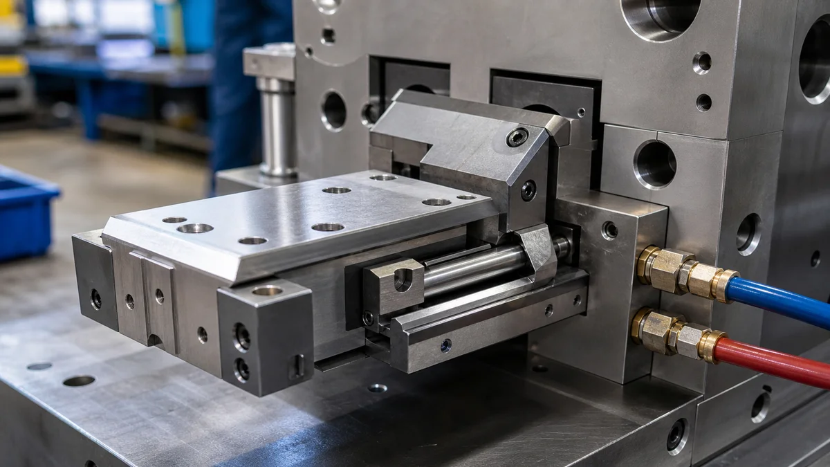
A slide forms part of the cavity while the mold is closed. It must remain in its molding position under injection load, then retract far enough to clear the part before ejection. The approval package should therefore connect the finished-part requirements with the proposed mechanism.
Review these items before releasing the design:
- Travel: Show undercut depth, movement direction, molded position, fully retracted position, and clearance from the part and adjacent components.
- Draft: Define release draft on applicable slide-formed faces. At least 1° per side is a published design recommendation3, but the final value remains conditional on resin, texture, draw depth, wall geometry, and surface requirements.
- Positive locking: Explain how the slide is held against molding pressure rather than relying on the actuator alone.
- Guidance and support: Identify bearing and guiding surfaces that maintain alignment throughout travel.
- Shutoffs: Locate interfaces between moving and fixed steel, the resulting witness line, and surfaces exposed to wear or flash.
- Cooling: Show how heat leaves a moving block that forms a thick, dimensional, or appearance-critical region.
- Service access: Confirm that sliding and wear components can be inspected, adjusted, or replaced without unnecessary mold disassembly.
A practical mold concept drawing should show the slide envelope at both travel limits. This exposes conflicts with cooling channels, ejector components, neighboring actions, fasteners, and the available mold envelope.
Common specification mistake: A drawing states only “side action required.” It does not identify whether the slide witness line is acceptable on the cosmetic face, whether a slide-formed dimension is critical, or whether a nearby heavy wall makes cooling important. Define those finished-part requirements and ask the toolmaker to document locking, guidance, cooling, shutoff wear, and maintenance access.
How Should Lifter Angle, Stroke, Clearance, and Support Be Checked?
Check lifter angle and ejector stroke together because they determine available lateral movement. Confirm that the lifter clears the undercut with additional margin, remains guided throughout its motion, avoids interference, and has sufficient support to limit deflection, binding, galling, flash, and uneven wear.
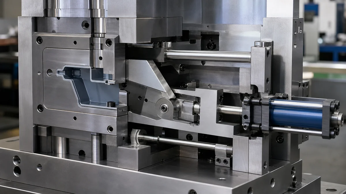
A lifter converts ejector travel into outward ejection and sideways release. A larger angle can provide more lateral movement for the same stroke, but it also changes side loading, sliding contact, mechanism length, and binding risk. Approving the angle without the complete motion and support plan is inadequate.
The available research presents 5°–15° as a practical review range and cautions against exceeding 15° in standard applications. Treat this range as a design-review reference4, not a universal limit. Resin shrinkage, undercut depth, ejector stroke, part stiffness, contact geometry, lifter length, and production duty may support a different toolmaker recommendation.
Lateral movement should clear the undercut rather than simply equal its nominal depth. An additional 0.5–1.0 mm is a supported review reference. The toolmaker should show the lifter travel calculation and verify clearance at intermediate positions, where interference can occur even when both endpoints appear acceptable.
What should the lifter motion review show?
Request a section or motion diagram identifying lifter angle, undercut depth, ejector stroke, calculated lateral travel, clearance margin, unsupported length, guide locations, bearing surfaces, and closest interference points. It should also show when the molded feature stops contacting the lifter.
Scenario: An internal snap needs 3 mm of lateral release. A steep lifter produces the required motion within the available stroke, but the long lifter is supported mainly at one end. The concept clears geometrically yet may deflect under load. Review guidance, bearing length, wear pairing, shutoff loading, and whether reducing the undercut would produce a more stable mechanism.
Sample inspection should cover the lifter-formed profile, shutoff flash, dragging, scuffing, stress whitening, sticking, and changes in witness lines.
When Does an Undercut Need an Unscrewing Action or Collapsible Core?
Consider an unscrewing action or collapsible core when the feature requires rotational release or surrounds the core so ordinary lateral movement cannot free it. Internal threads, threaded necks, and deep circular grooves should be separated from conventional hooks or snaps during DFM and quotation.
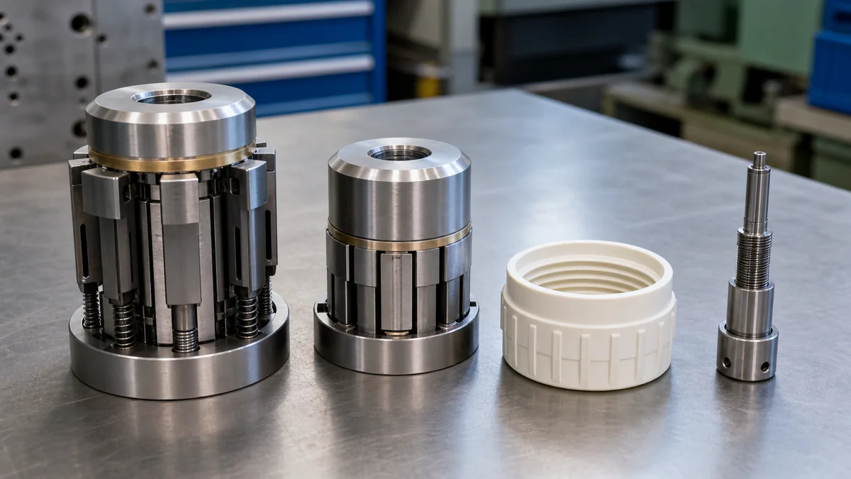
Slides and lifters create directional clearance. They work only when the forming steel can move along a practical path that frees the molded geometry. A continuous internal thread or annular undercut may remain trapped after ordinary lateral movement, so it needs a different release principle or a redesign.
| Molded geometry | Initial release concept | Approval question |
|---|---|---|
| External side hole or recess | Slide | Does lateral retraction clear the full feature and part? |
| Local internal hook or snap | Lifter | Do angle and ejector stroke provide adequate clearance? |
| Continuous internal thread | Unscrewing action | Must the core rotate through the complete thread path? |
| Deep internal annular groove | Collapsible core or redesign | Can the collapsed core pass through the restricted opening? |
| Change-prone, limited-demand detail | Handload or redesign | Is manual loading compatible with production and inspection intent? |
An unscrewing mold mechanism5 rotates the threaded core or the part through its release path. A collapsible core reduces its effective diameter after molding so it can pass through a smaller opening. Both change mold architecture, action sequencing, cooling opportunities, service access, validation, and tooling risk.
For threaded geometry, disclose thread form, pitch, depth, engagement length, resin grade, wall thickness, shrinkage considerations, and permitted witness areas. Describing it only as an internal undercut hides the rotational requirement.
A hand-loaded insert may suit some production plans, but insertion, verification, removal, and handling become part of every molding cycle. Compare it with automatic actions using the same quantity and labor assumptions.
Where function permits, invite alternatives such as a partial thread, interrupted profile, separate insert, post-mold assembly, or revised opening. Define the finished interface and its critical tolerances, then let suppliers compare release concepts without weakening the required function.
How Should Mold-Action Sequencing and Sample Approval Be Defined?
Document when every slide, lifter, ejector, and other action locks, moves, clears, and returns. Then approve molded samples against undercut dimensions, witness areas, flash, scuffing, sticking, cosmetic damage, and evidence of interference so correct mechanism timing is verified on the delivered part.

A multi-action mold must keep the part and moving components from occupying the same space at the wrong time. Slides generally retract before ejection begins. Lifters travel with the ejector system and must stay synchronized with the part. Additional cores or unscrewing actions introduce further dependencies.
Use this mold action sequence approval checklist6:
- All ejectors and actions return before mold closing.
- Slides and moving cores reach their molding positions.
- Positive locks engage before filling and packing.
- The mold opens to the required separation point.
- Slides or other independent cores retract fully.
- Ejectors and lifters move only after the necessary clearances exist.
- The part releases without dragging across shutoffs or cosmetic faces.
- The ejection system returns fully before the next closing movement.
- Interference is checked throughout every intermediate position.
- Any action-position monitoring is identified with its intended purpose.
Scenario: A housing uses two external slides and one internal lifter. If ejection begins before either slide has cleared, an external hook may tear or transmit an unintended side load into the mechanism. If the lifter passes too close to a rib, the part can scuff or remain trapped. Checking only fully open and fully closed states would miss both risks.
Sample approval should connect the sequence to measurable part requirements. Inspect critical undercut depth and position, local profile, flash, shutoff witness lines, drag marks, stress whitening, deformation, sticking, and cosmetic damage. Define viewing conditions for appearance-critical zones and identify the measurement condition for flexible features.
Initial sample approval confirms the inspected samples, not continuing production stability. If recurring checks are required, state cavity identification, sampling frequency, inspected characteristics, and reporting expectations. An undercut or mechanism revision should trigger an agreed level of renewed dimensional and functional approval.
When Is an Undercut Worth the Added Tooling Complexity?
Retain an undercut when it provides necessary retention, sealing, clearance, or assembly value that a simpler feature cannot deliver. Remove or revise incidental and cosmetic undercuts when their benefit does not justify additional mechanisms, fitting, cooling constraints, maintenance, validation, inspection, and design-change exposure.
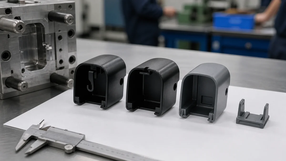
The useful question is not simply whether an undercut can be molded. Determine whether its functional value justifies the complete route7 needed to produce, maintain, inspect, and approve it. That route may include moving components, wear-sensitive shutoffs, restricted cooling, more complex sequencing, and additional sample work.
| Feature classification | Preferred review decision | Specification evidence needed |
|---|---|---|
| Function-critical | Retain and control precisely | Load, fit, sealing, retention, tolerance, inspection method |
| Assembly-related | Compare alternate interfaces | Mating geometry, assembly direction, service access, allowed redesign |
| Cosmetic | Remove or simplify where practical | Visible zone, witness-line limits, texture and appearance criteria |
| Incidental CAD detail | Remove after confirmation | Evidence that it has no functional or assembly purpose |
Potential simplifications include opening a recess to the parting line, changing assembly direction, relocating a clip, dividing a feature into accessible elements, or using a separate component. Review each change against resin grade, wall thickness, load path, draft, finish, tolerance, and production intent.
Example: A shallow hook on a hidden face locates another component during assembly. Before committing to a lifter, compare it with an accessible snap, through-slot, separate retainer, fastener, or revised assembly sequence. This teaching example does not imply that one option is universally stronger or less costly.
Quantity and design maturity affect the comparison. A handload may be considered for a changing or limited program, while stable recurring demand may support an automatic action. High annual demand does not correct weak guidance, inadequate cooling, poor ejection, or inaccessible wear surfaces.
Request alternative quotations using equivalent assumptions: the same resin, revision, quantities, cosmetic standard, critical tolerances, inspection scope, and delivery expectations. Otherwise, apparent savings may come from omitted requirements rather than a better design.
What Should an Undercut-Specific Injection Mold RFQ Include?
Send a controlled model-and-drawing package that defines resin, demand, pull direction, every undercut, critical dimensions, cosmetic limits, inspection, sample approval, acceptable mechanisms, revision status, and delivery expectations. Comparable quotations require suppliers to evaluate the same geometry, tooling scope, production intent, and acceptance evidence.

An injection mold RFQ should define the delivered part and expose tooling risks without forcing an unsupported mechanism. The 3D model communicates complete geometry; the controlled 2D drawing carries tolerances, datums, finish requirements, revision status, and inspection criteria that nominal CAD may not convey.
Use this undercut mold RFQ checklist8:
- Current 3D CAD model and controlled 2D drawing.
- Part number, units, active revision, and governing document if files conflict.
- Exact resin grade, filler, additives, color, and approved alternatives.
- Immediate quantity, annual demand, lot expectations, and prototype or production intent.
- Proposed primary pull direction and any acceptable alternate orientation.
- Undercut map listing feature ID, location, type, direction, depth, and access restriction.
- Function of each undercut: retention, sealing, clearance, assembly, or cosmetic.
- Nominal wall thickness, ribs, bosses, draft restrictions, texture, and cosmetic zones.
- Critical tolerances, functional datums, warpage limits, and measurement condition.
- Surface finish or texture, acceptable witness lines, shutoff marks, gate restrictions, and parting-line preferences.
- Permission to propose slides, lifters, handloads, collapsible cores, unscrewing actions, or geometry revisions.
- Required sequence diagrams, interference review, and mechanism-approval deliverables.
- Sample approval scope, cavity identification, dimensional reporting, functional checks, and cosmetic criteria.
- Tooling ownership, expected documentation, approval milestones, and delivery expectations.
Use correct manufacturing terminology. Plastic injection molding fills a mold with molten polymer. CNC machining removes material from solid stock. CNC turret punching creates sheet features with programmed punch tools. Metal stamping cuts or forms sheet using dedicated dies. Sheet metal fabrication may combine cutting, punching, bending, welding, hardware installation, and finishing.
“CNC turret punching, CNC punch press, CNC-controlled stamping equipment, or metal stamping depending on the actual process” is not one standard process term. If it appears in a related request, clarify whether the intended process is CNC turret punching, a CNC punch press operation, CNC-controlled stamping equipment, or dedicated die stamping. None describes the polymer molding process addressed by this RFQ.
For a mold recommendation or quotation, send the 3D model, controlled 2D drawing, exact resin grade, quantity and annual demand, prototype or production intent, undercut map, pull direction, critical tolerances, surface finish or texture, inspection expectations, active revision, and delivery requirements. Mark which features may be redesigned.
References
-
DFM Guidelines for Injection Molding - Undercuts are features like clips or thru-holes that can't be milled in a standard vertical (Z-axis) milling setup. Learn about designing for cams and inserts ... ↩
-
Using Injection Molding Side Action for Design Optimization - In contrast to lifters, this type of side action creates and releases external undercut features. They offer versatile actuation options ... ↩
-
Injection Mold Slide And Lifter Design Guideline - All shut-off surfaces must have a minimum of three degrees draft in direction of slide travel. Two angle pins will be required on any slide design. Slides with ... ↩
-
Lifter Design Injection Mold: Internal Undercut Solutions - The lifter angle must not exceed 15° for standard applications … must include 0.5–1.0 mm clearance beyond the undercut depth. 5–15°C above the ... ↩
-
Mastering Undercuts in Injection Molding: Solving Internal ... - A more advanced option for internal undercuts is the collapsible core, designed to release threads or recessed features without requiring a ... ↩
-
Injection Mold Side-Action Review Checklist: Slider, Lifter, ... - Review slider and lifter risks before steel cut. Verify undercut release, interference, travel margin, positive stops, reset logic, and supplier review ... ↩
-
Injection Molding Sliders and Lifters vs. Handloads - Injection molding sliders usually consist of a guide pin, slider body, forming surface, press block, wear plate, and wedge. ↩
-
Plastic Injection Molding RFQ Checklist for Quote-Ready ... - A plastic injection molding RFQ should include 3D CAD, a 2D drawing with CTQ dimensions and datum references, the exact resin grade, annual volume, surface ... ↩