
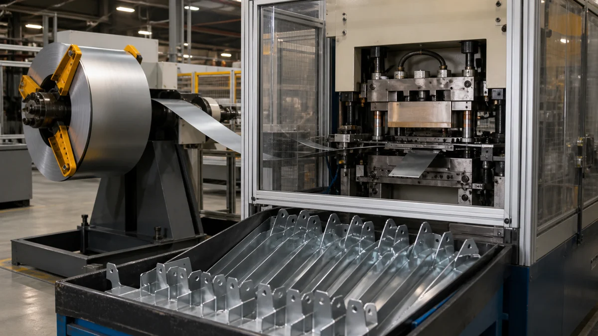
Progressive die stamping may become economically attractive near 50,000 parts per year, while some simple, stable parts may justify evaluation between 30,000 and 50,000. These are useful screening ranges, not automatic approval thresholds. Geometry, material behavior, tolerances, tooling complexity, inspection, secondary operations, and forecast confidence can move the crossover substantially.
The sound comparison covers the entire production program. Dedicated tooling may reduce recurring operations and handling, but those savings matter only when the design and demand remain stable long enough to recover the initial investment.
The following decisions establish whether the part fits a progressive process, whether its projected demand supports the tooling commitment, and what information manufacturers need to prepare comparable quotations.
Is Annual Volume High Enough to Consider Progressive Die Stamping?
Annual demand near 50,000 parts is a useful point for considering progressive die stamping, while simple parts may justify evaluation between 30,000 and 50,000. Volume remains a screening factor because geometry, material, tolerances, tooling complexity, secondary work, and forecast stability determine the actual crossover.
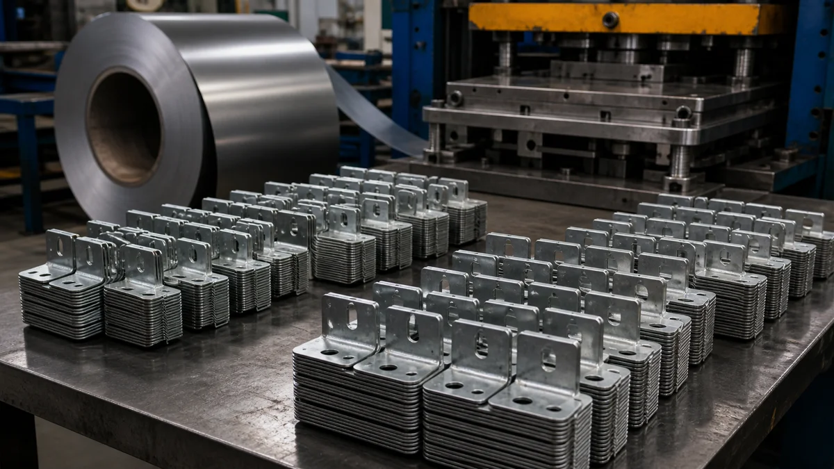
Start with projected annual demand, then place it within the complete program. An order for 50,000 parts in one year is economically different from repeat demand of 50,000 parts per year across a stable multiyear program. Lot sizes, release frequency, program life, and forecast confidence determine how many acceptable parts can absorb the tooling investment.
| Annual demand situation | Tooling exposure | Sourcing decision |
|---|---|---|
| Below 30,000 parts | Dedicated tooling is spread across fewer parts | Compare turret punching, staged stamping, and flexible sheet metal fabrication first |
| 30,000–50,000 simple parts | Economics depend heavily on geometry and design stability | Request progressive and lower-commitment quotations when the design is mature |
| Around 50,000–100,000 parts | Tooling amortization may become more favorable | Compare complete delivered-part cost across the expected program |
| Much higher repeat demand | Recurring operations carry more economic weight | Evaluate standard progressive production and, when appropriate, a high-speed strategy |
These production-volume screening ranges1 guide quotation strategy; they do not select the process. A flat bracket with repeatable holes and modest forming demand may justify tooling sooner than a component with several structural forms, critical hole-to-form relationships, or extensive secondary finishing.
Scenario: A buyer forecasts 45,000 parts annually but expects two drawing revisions during launch. The volume supports obtaining a progressive-die quotation, yet revision exposure may favor CNC turret punching or another flexible route for early lots. Once the controlled drawing and forecast stabilize, the buyer can compare dedicated tooling using firmer program assumptions.
Is Progressive Die Stamping the Process the Part Actually Requires?
Progressive die stamping fits parts that can move as strip material through dedicated stations performing operations in a fixed sequence. It is distinct from CNC turret punching, CNC machining, general sheet metal fabrication, and plastic injection molding, so buyers must define the intended process before comparing quotations.

In progressive die stamping, coil or strip advances by a controlled pitch through a dedicated die. Individual stations may punch, bend, coin, emboss, form, or shear. The work usually remains connected to a carrier strip until final separation. This operating principle is useful when several dependent sheet-metal operations can be integrated into a stable sequence.
| Process | Material and operating principle | Appropriate selection question |
|---|---|---|
| Progressive die stamping | Strip passes through dedicated sequential die stations | Can the required cutting and forming operations progress reliably while the carrier controls the work? |
| CNC turret punching | Programmed physical punch tools act on sheet | Does the part mainly require holes, slots, cutouts, or limited localized forms? |
| CNC machining | Cutting tools remove material from solid stock | Does the part require machined bores, pockets, faces, or solid geometry? |
| Sheet metal fabrication | Separate cutting, punching, bending, welding, and finishing operations may be combined | Does the design require a flexible route or operations outside one die sequence? |
| Plastic injection molding | Molten polymer fills a mold cavity | Is the component a molded polymer part rather than a formed sheet-metal part? |
“CNC turret punching, CNC punch press, CNC-controlled stamping equipment, or metal stamping depending on the actual process” is not a standard process definition. It may informally refer to CNC turret punching, a CNC punch press, CNC-controlled stamping equipment, or general metal stamping. An RFQ using that phrase should identify the material form, required operations, and intended production method.
These processes should not be treated as interchangeable. A stamped bracket, machined block, fabricated enclosure, and molded plastic housing can belong to the same assembly, but they have different geometry rules, tooling commitments, material behavior, and inspection requirements.
Does the Program Justify Standard or High-Speed Progressive Stamping?
Standard progressive stamping may warrant evaluation around the broader 50,000-part annual range, while high-speed progressive tooling may require demand closer to 500,000 or more. Even then, feed length, geometry, material behavior, station sequence, strip control, inspection, and part handling must support the proposed operating strategy.
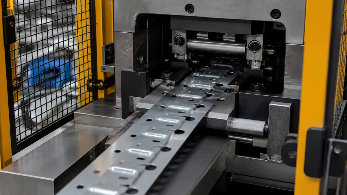
High-speed stamping is not simply standard progressive stamping paired with a larger purchase order. The process must continue feeding, locating, cutting, forming, clearing scrap, and discharging parts reliably under the proposed conditions. Features that require substantial material movement or additional control may limit the suitable production strategy even when annual demand is high.
Require each high-speed proposal to define:
- The press and feed strategy in functional terms.
- Strip progression and feed length for each cycle.
- The number and purpose of the die stations.
- How the carrier strip supports and locates the work.
- Which cutting, coining, bending, or forming operation constrains the process.
- How scrap removal and finished-part handling are incorporated.
- Which characteristics require in-process or finished-part inspection.
Example: A program calls for 600,000 small brackets annually. That demand supports evaluating high-speed production, but the bracket also contains a structural form and a critical hole-to-form relationship. Strip control and forming behavior still need engineering review; quantity alone does not establish high-speed progressive stamping feasibility2.
When standard and high-speed approaches are both proposed, the quotations should state their respective tooling, feed, inspection, and operating assumptions. Otherwise, a buyer may compare recurring prices based on materially different production plans. The final choice should remain conditional on material grade, geometry, tolerances, finish, lot pattern, program duration, and the required acceptance evidence.
Can the Specified Material Run Reliably Through a Progressive Die?
Material suitability depends on the exact grade, thickness, temper or condition, grain direction, and final property requirements. The manufacturer must evaluate how the material will cut, bend, coin, form, and spring back while the carrier strip continues locating and transporting the work through every die station.
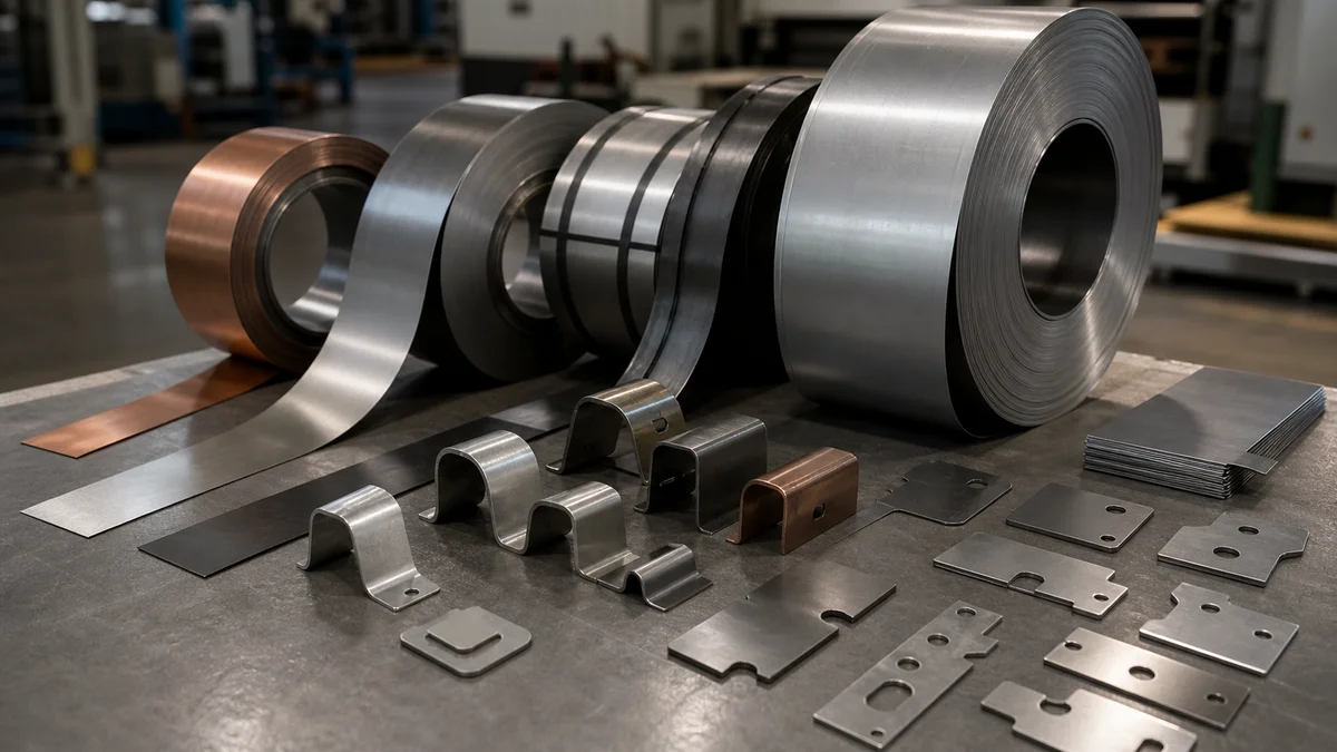
A description such as “steel” or “aluminum” is too broad for progressive-die planning. Grades and material conditions can respond differently to shearing and forming. Thickness affects cutting and forming requirements as well as strip layout, while grain direction may influence bend orientation and the placement of parts within the strip.
Springback3 is the material’s elastic recovery after forming force is removed. It can alter a bend angle or the final position of a formed feature. The drawing should define the required delivered geometry, allowing the proposed process to be evaluated against material condition, bend direction, and forming sequence. Buyers should avoid prescribing undocumented die compensation.
Provide these material inputs for review:
- Exact material grade and temper or condition.
- Nominal sheet or strip thickness and its drawing requirement.
- Grain-direction restrictions where forming or function makes them relevant.
- Required material documentation and substitution controls.
- Cosmetic face and permitted handling marks.
- Required burr direction or burr-side orientation.
- Finish applied before or after stamping.
- Functional characteristics that forming could affect.
The finish sequence also matters. Pre-finished stock may require controls for handling and forming marks. A post-stamping coating may create finish buildup at edges or in features, so the drawing should state whether affected dimensions apply before or after finishing.
No single thickness range or material family proves suitability for every progressive part. Engineering review should consider feature spacing, bend direction, forming severity, carrier design, strip progression, springback, and the final acceptance condition.
Can the Part Geometry Progress Through a Stable Station Sequence?
The geometry fits progressive stamping only when the part can remain located and supported as its features are created through a feasible strip progression. Deep draws, substantial material movement, difficult release, or forms that cannot remain attached to a carrier may require transfer stamping or another fabrication route.
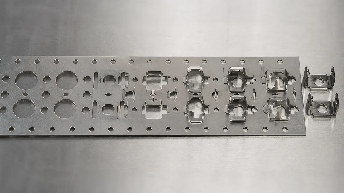
A progressive-die review should begin with feature sequence rather than the finished silhouette. Tooling engineers must determine when material is removed, where carrier connections remain, how the work is located, and when bends or forms can be introduced without obstructing later stations.
| Feature type | Required geometry review | Possible consequence |
|---|---|---|
| Holes and cutouts | Spacing, sequence, edge distance, and remaining carrier strength | Early material removal may weaken strip control |
| Bends | Direction, springback, station access, and later interference | A formed flange may block downstream tooling access |
| Embosses and light forms | Material flow, support, cosmetic face, and nearby features | Local deformation may affect adjacent geometry |
| Coined features | Functional geometry and relationship to later stations | Station order may control final location or profile |
| Structural or deep forms | Material movement, support, and release | Transfer stamping or another route may be more suitable |
| Final separation | Cut edge, burr direction, part release, and handling | Separation strategy affects delivered edge condition |
Feature relationships often matter more than isolated dimensions. A hole punched early may move relative to a form created later if strip location or material flow is not controlled. The drawing should identify functional datums and critical hole-to-form, form-to-edge, and mating relationships.
A common specification mistake is sending only the finished 3D model. A controlled 2D drawing and, when available and authoritative, the flat pattern are also needed. The package should distinguish cut features, bends, embosses, coined regions, structural forms, and secondary operations.
Substantial material movement or inadequate carrier support may point to transfer stamping. A changing part dominated by programmable holes and cutouts with limited forming may instead suit CNC turret punching or flexible sheet metal fabrication.
Is the Design Stable Enough to Approve Dedicated Tooling?
Approve dedicated progressive tooling only when the controlled drawing, material specification, production intent, and forecast are sufficiently stable. Changes to profiles, holes, bends, forms, thickness, or critical relationships may require die modification or replacement and can erase the savings expected from repeat production.

Progressive tooling embodies a specific strip layout and station sequence. A revision can therefore affect more than the feature being changed. Moving a hole may alter carrier strength or station relationships. Changing a bend can affect progression, clearance, and springback. A thickness change can influence cutting, forming, and material-flow assumptions throughout the die.
Before tooling release4, confirm:
- The 3D model and controlled 2D drawing carry the intended revision.
- Conflicts between files are resolved and the controlling document is identified.
- Material grade, condition, and thickness are released.
- Functional datums and critical tolerances are established.
- Cosmetic face, burr direction, finish, and secondary operations are defined.
- Prototype, pilot, and repeat-production intent are distinguished.
- Remaining engineering decisions are visible rather than hidden inside forecast uncertainty.
- Annual demand, program life, and lot pattern have a stated confidence level.
Scenario: A bracket has passed a fit check, but engineering is still evaluating two hole locations and a bend angle. Releasing a progressive die would freeze decisions that remain open. CNC turret punching followed by bending, or another flexible sheet metal route, may support validation lots while preserving revision freedom.
A successful prototype does not by itself establish production readiness. Tooling approval also needs agreement on repeat-lot acceptance, inspection evidence, finishing, material control, and revision release. Dedicated tooling becomes defensible when the manufacturing specification and demand are stable enough for the program to recover its non-recurring investment.
Which Stamped-Part Tolerances Are Functionally Critical?
Critical tolerances are the dimensions and geometric relationships that protect assembly or performance, including datum-based hole positions, formed-feature locations, mating edges, flatness, profiles, and burr limits. Specify them separately because progressive stamping does not provide one uniform tolerance capability across every feature or station.
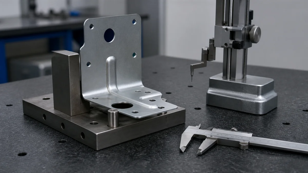
Tolerance planning should follow function and the manufacturing sequence. A clearance cutout rarely needs the same control as a locating hole. Likewise, the nominal bend angle may matter less than the final position of a formed flange relative to an assembly datum.
| Controlled characteristic | Drawing definition needed | Inspection consequence |
|---|---|---|
| Hole position | Functional datum and whether the requirement applies after forming | Measurement must reproduce the specified datum alignment |
| Formed-feature location | Whether location, angle, or profile controls function | Inspection must address the completed form, not only the flat blank |
| Flatness | Whole part or a defined functional region | Support and measurement condition need to match the requirement |
| Mating edge or profile | Controlled interface and delivered condition | Deburring or finishing may change the accepted edge or surface |
| Burr limit and direction | Permitted burr side and functional consequence | Edge inspection must distinguish direction, height, and handling risk |
| Cosmetic surface | Controlled area and unacceptable process marks | Visual criteria should apply to the identified face |
Blanket close tolerances can increase die complexity and inspection effort without revealing the assembly requirement. Functional datums and appropriate geometric controls are more useful when position, profile, or flatness matters. Review the resulting tolerance stack-up5 against station sequence, strip location, material flow, springback, tool condition, finishing, and inspection method.
Example: A drawing tightly controls every outside dimension but does not relate the mounting-hole pattern to the formed flange. It remains unclear whether overall size, hole position, or flange alignment controls assembly. A functional datum scheme makes that relationship explicit without tightening unrelated dimensions.
Acceptance should refer to the finished condition whenever forming, deburring, or finish buildup can change the result.
How Should Finished Progressive-Stamped Parts Be Inspected and Approved?
Inspection should verify the delivered part after stamping, forming, deburring, finishing, and any secondary operations affecting acceptance. The RFQ must distinguish initial sample approval from continuing production controls and define critical characteristics, inspection methods, reporting scope, sampling expectations, and the controlled drawing revision.

Inspection of an early blank or intermediate station can help develop the process, but it cannot establish final acceptance. Forming may change hole relationships or flatness, deburring changes edge condition, and finish buildup may affect appearance or dimensions. The inspection plan should follow the complete manufacturing route.
Define the approval basis before quotation:
- Drawing and model revisions used for acceptance.
- Critical dimensions and geometric controls.
- Whether requirements apply before or after forming and finishing.
- Cosmetic face, surface condition, burr direction, and edge criteria.
- Formed-feature angle, location, profile, and flatness requirements.
- Required initial sample results and report content.
- Inspection method for each critical characteristic when method affects interpretation.
- In-process checks needed for features created at different stations.
- Sampling or selected full-inspection requirements for repeat lots.
- Final dimensional report and material-documentation expectations.
- Approval responsibility and the required response to nonconforming results.
Initial sample acceptance6 means the inspected samples met the defined approval basis. It does not independently prove continuing process capability or establish inspection frequency for future lots. Those ongoing controls need separate definition.
Measurement should fit the characteristic. A simple size, a datum-based positional control, a formed profile, flatness, and a cosmetic face require different approaches. Buyers need not prescribe equipment without a functional reason, but they should specify the evidence expected at delivery. This gives manufacturers enough information to include inspection time, reporting, and repeat-lot controls in the quotation rather than treating them as undefined additions.
Does Progressive Stamping Deliver the Lowest Total Program Cost?
Progressive stamping delivers the lowest total program cost only when recurring savings recover die development, tryout, approval, and launch investment across stable demand. Compare complete delivered-part routes using consistent quantities, program life, material, secondary operations, inspection, delivery patterns, and revision assumptions instead of unit price alone.

The economic comparison should separate non-recurring investment from recurring delivered-part cost. It should also show what changes if demand falls, the drawing is revised, or the program ends earlier than forecast.
| Cost driver | Progressive die stamping | Flexible sheet metal route |
|---|---|---|
| Tooling and preparation | Die design, manufacture, tryout, and adjustment | Programming, standard tools, setups, and any limited fixtures or stage tooling |
| Recurring processing | Sequential operations may be integrated in the die | Cutting, punching, bending, or other operations may remain separate |
| Material utilization | Driven by strip width, pitch, carrier design, and scrap layout | Driven by sheet nesting, blank size, and fabrication route |
| Inspection | Initial approval plus specified continuing controls | Setup, in-process, and final checks for the selected route |
| Revision exposure | Changes may require die modification or replacement | Some changes may be handled through programming or flexible tooling |
| Delivery pattern | Economics depend on repeat demand and release quantities | May better accommodate smaller or less predictable lots |
Scenario: Two quotations cover the same annual demand. The progressive option includes dedicated tooling and lower recurring processing; the turret-punched and formed option requires less initial commitment but more operations per lot. A total program cost comparison7 adds tooling, samples, material, secondary finishing, inspection, packaging, and delivery to realistic recurring demand. It should also test reduced-volume and revision scenarios.
Require separate amounts for tooling, tryout, samples, production parts, secondary operations, inspection, and delivery. Each quantity tier must use the same material grade, drawing revision, tolerances, finish, inspection scope, and shipment assumptions. Otherwise, an apparent break-even point may be caused by omitted requirements rather than a better manufacturing route.
Can the Tooling Schedule and Forecast Risk Support the Launch?
The launch supports progressive tooling only when die design, manufacture, tryout, adjustment, sample inspection, and approval fit the required schedule and the forecast is stable enough to protect the investment. If parts are needed earlier, a suitable flexible sheet metal route may serve as an interim method.
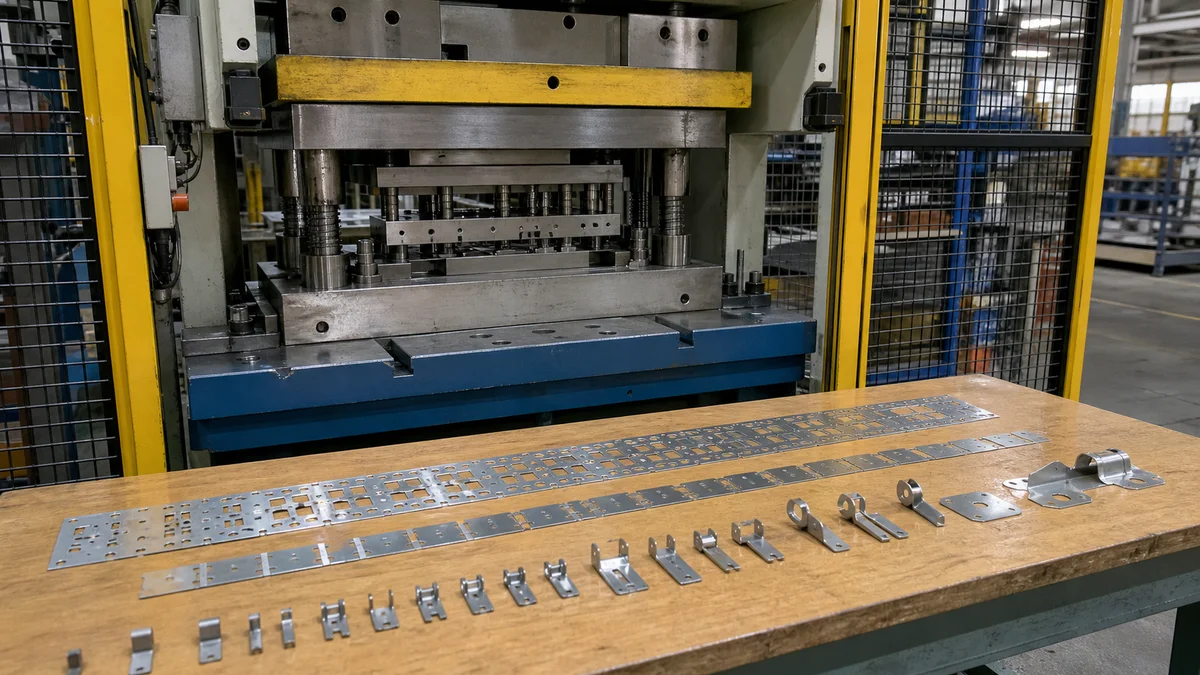
A progressive-die schedule is a chain of dependent decisions, not a single tooling completion date. The manufacturer must interpret the released files, establish the strip and station strategy, manufacture the die, conduct tryout, resolve observed issues, produce samples, and obtain approval against controlled requirements.
A practical tooling release sequence8 includes:
- Release the drawing, model, material specification, and forecast.
- Review the strip layout and process concept.
- Manufacture and prepare the tooling.
- Conduct tryout and make necessary adjustments.
- Produce samples using the intended material and revision.
- Evaluate dimensional, formed-feature, cosmetic, and finishing requirements.
- Authorize repeat production after the defined approval evidence is accepted.
Changes after these decision gates can affect cost and schedule. Moving a critical feature may require more than a local tool edit if the revision changes station relationships, carrier strength, material flow, or inspection access.
A common launch mistake is releasing tooling against an optimistic forecast while the drawing remains unsettled. When production parts are required before tryout and approval can finish, CNC turret punching and bending or another flexible fabrication route may provide an interim option if the geometry permits. Those parts still need their own controlled material, tolerance, surface finish, and inspection plan. Approval of that route does not automatically approve the later progressive process.
The release decision should balance launch timing with forecast confidence, program duration, pilot demand, revision maturity, and the consequence of delayed parts. Press cycle time alone does not answer that risk question.
What Must a Progressive Die Stamping RFQ Include?
A progressive stamping RFQ must define the part, material, demand, production intent, acceptance requirements, revision, and delivery plan well enough to price tooling and recurring production consistently. It should also state whether manufacturers may propose transfer stamping, CNC turret punching, or another sheet metal fabrication route.

Send every bidder the same controlled package so quotation differences reflect manufacturing strategy rather than missing information. If the 3D model, drawing, or flat pattern conflicts, identify which document controls and resolve the discrepancy before tooling approval.
Progressive die stamping RFQ checklist
- 3D model: Current finished geometry at the intended revision.
- Controlled 2D drawing: Dimensions, functional datums, tolerances, notes, and revision status.
- Flat pattern: Include it when controlled; otherwise require development and confirmation of the progression.
- Material: Exact grade, sheet thickness, temper or condition, and permitted substitutions.
- Material controls: Documentation, source restrictions, and traceability expectations when required.
- Demand: Immediate quantity, annual usage, program life, lot sizes, and release pattern.
- Production intent: Design learning, functional validation, pilot production, or repeat production.
- Forecast: Confidence level, known demand risks, and expected engineering revisions.
- Critical characteristics: Hole positions, formed-feature relationships, flatness, profiles, mating edges, and datum scheme.
- Edge requirements: Burr limit, burr direction, edge condition, and handling concerns.
- Appearance: Cosmetic face and acceptable surface condition.
- Forming requirements: Bends, embosses, coined areas, structural forms, springback-sensitive relationships, and final acceptance state.
- Surface finish: Pre- or post-stamping finish, masking, finish buildup concerns, and when affected dimensions apply.
- Secondary operations: Deburring, tapping, welding, assembly, marking, or other required work.
- Inspection expectations9: Initial sample evidence, applicable inspection methods, reports, sampling, and continuing controls.
- Delivery: Required dates, shipment pattern, packaging, and partial-shipment expectations.
- Process alternatives: Permission to quote progressive stamping, transfer stamping, CNC turret punching, or another sheet metal route.
A complete package exposes tooling assumptions, geometry risk, inspection effort, and schedule dependencies before approval.
For a process recommendation or quotation, send the current 3D model, controlled 2D drawing, material grade and thickness, immediate and annual quantities, prototype or production intent, critical tolerances, surface finish, inspection expectations, revision level, program life, forecast confidence, and delivery requirements.
References
-
Progressive Sheet Metal Stamping for High-Volume Parts - Investing in a progressive die is an exercise in amortization logic. ... Tooling costs are typically amortized over the total production volume. ↩
-
Progressive Die Stamping | A Comprehensive Guide - Each station performs a specific operation (e.g., punching, bending, coining, or blanking), and the metal strip advances with each press stroke until the final ... ↩
-
Bending of Sheet Metal | Metalworking - ASM Digital Library - As metal is bent through greater degrees of bend, the plastic zone is enlarged and springback is reduced for each degree of bend. Total springback is increased, ... ↩
-
Progressive Die Strip Layout Optimization for Minimum ... - The progressive die design starts with 3D modeling of the part and continues with process sequence planning and strip layout. The strip layout ... ↩
-
True Position - Position Tolerance - True Position, or just Position as the ASME Y14.5 standard calls it, is defined as the total permissible variation that a feature can have from ... ↩
-
Initial Product Inspection: Catching Issues Before ... - In global manufacturing, the first units off the line tend to reveal how the rest of the order will go. If the initial 5% is produced ... ↩
-
Why Is Metal Stamping So Cost-Effective? - Tooling Amortization. At Talan Products, progressive die tooling typically ranges from $10,000 to $350,000 depending on part complexity and the ... ↩
-
Stamping Die Tooling Manufacturer Guide - Tryout is the first real test of the design. The die is installed in a press, trial material is run, and parts are checked. tryout → approval. The process ... ↩
-
What Is Sheet Metal Stamping? How Does It Work? - A useful stamping RFQ should let the supplier evaluate material, die type, forming risk, secondary operations, and inspection before tooling begins. ↩