
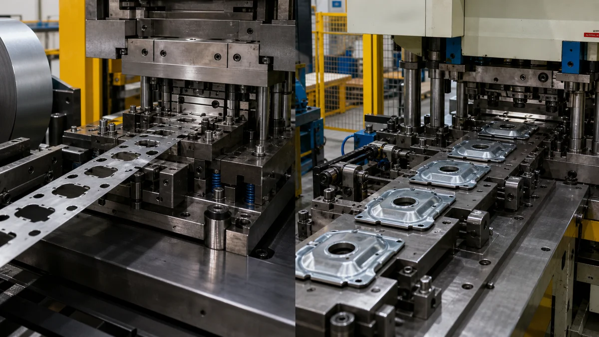
Choosing between progressive and transfer die stamping begins with the part, not the assumed press speed. The first questions are whether the work can remain attached to a carrier strip, how much material must move during forming, and whether an individual blank needs more space or reorientation between stations.
The decision also affects tooling commitment, material use, inspection planning, launch risk, and recurring production cost. High annual demand can strengthen the case for dedicated tooling, but it cannot make an unstable strip layout practical or remove the handling requirements of a deep, three-dimensional form.
A sound comparison follows the complete specification: part movement, process identity, material behavior, geometry, tolerances, throughput, program economics, design maturity, failure risk, and RFQ completeness.
Should the Part Stay on a Carrier Strip or Move as an Individual Blank?
Choose progressive tooling when the work can remain securely attached to a carrier strip through sequential cutting and forming stations. Choose transfer tooling when the blank must be separated early, repositioned independently, or given more space for drawing, re-striking, rotation, or release.
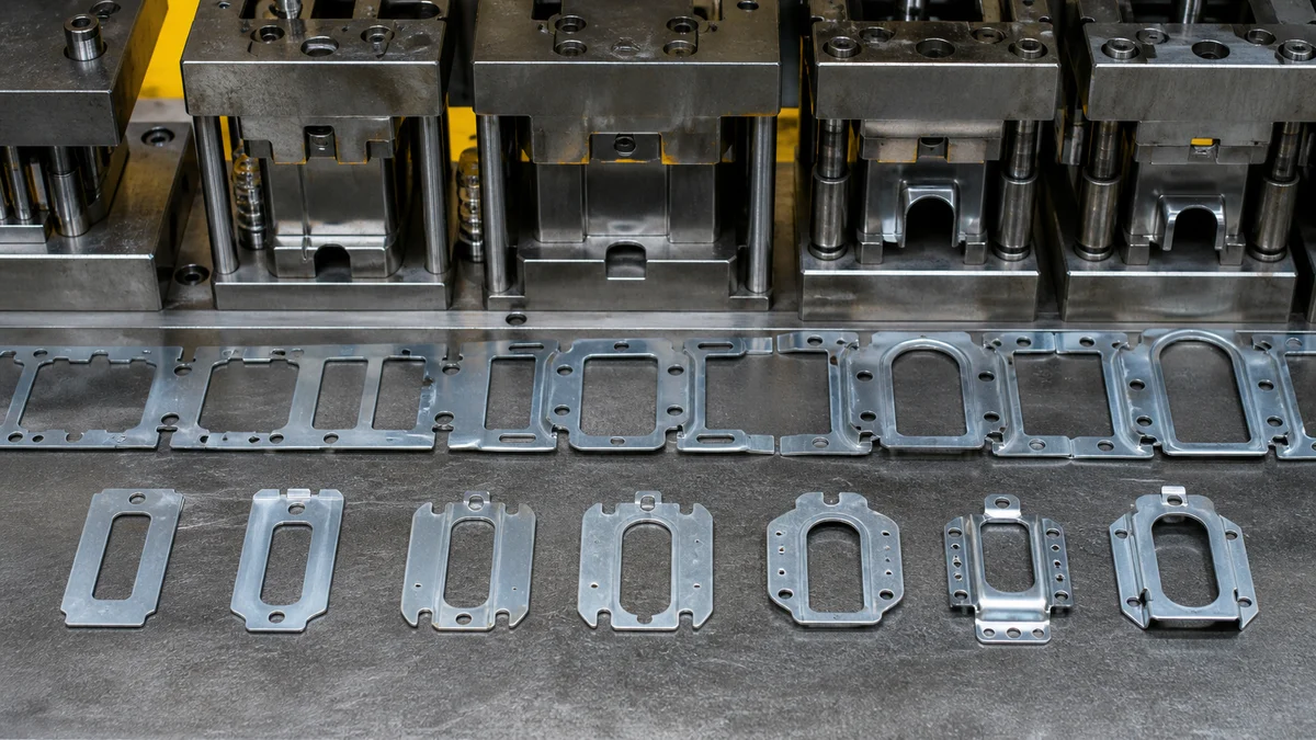
Progressive die stamping advances coil or strip by a defined pitch. Each press stroke performs work at several stations while the carrier connects the developing parts and preserves their position within the strip. Piercing, bending, coining, embossing, forming, and final separation may all occur in this integrated sequence.
Transfer die stamping begins with a separated blank or separates it near the start. A transfer mechanism then lifts, shifts, and places the blank into successive dies. Without a continuous carrier around the work, the tooling can provide more forming clearance and may change the part orientation between operations.
| Specification question | Progressive die | Transfer die |
|---|---|---|
| How is work advanced? | Strip and carrier move together | Individual blank moves between stations |
| When is separation performed? | Usually after the final operation | Before or early in the sequence |
| What controls location? | Feed pitch, pilots, carrier, and station relationships | Transfer placement, die location, and part retention |
| What geometry often fits? | Carrier-compatible piercing and forming | Larger or deeper three-dimensional forms |
The choice should not be reduced to overall part size. A small component may still need transfer handling when a deep form cannot remain supported. A larger but shallow part may permit a progressive concept when the strip layout, carrier strength, station spacing, and release path are practical.
Example: A bracket with pierced holes, two controlled bends, and a final cutoff may suit a carrier-based sequence. A cup-shaped part requiring deep drawing and re-striking may need individual blank movement, even if both parts use the same material grade.
Are You Specifying Die Stamping or a Different Manufacturing Process?
Specify progressive or transfer die stamping only when dedicated dies will repeatedly cut or form sheet metal. If the request says “CNC turret punching, CNC punch press, CNC-controlled stamping equipment, or metal stamping depending on the actual process,” clarify the intended operation because CNC turret punching, CNC punch press work, CNC-controlled stamping equipment, and general die stamping are not one standard process.
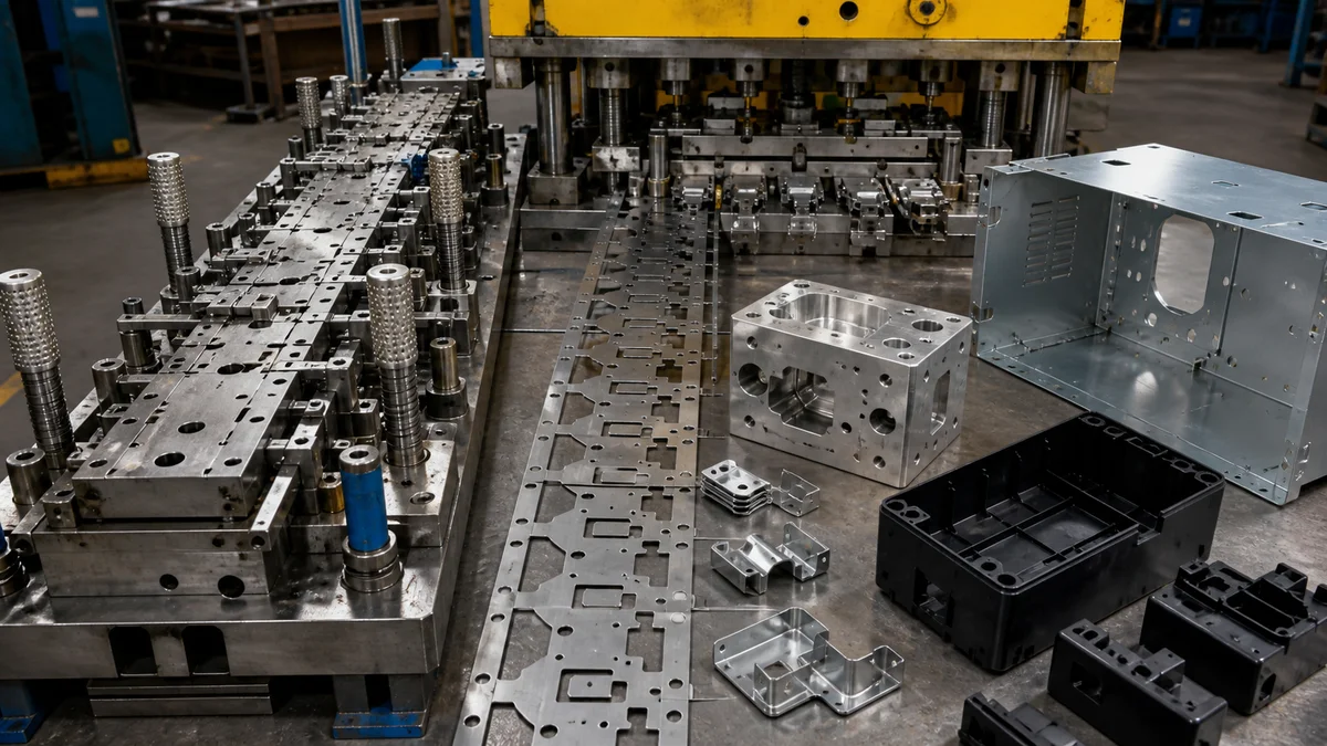
Process names matter because each route creates different tooling, geometry, quantity, and inspection assumptions. Quotations will not be comparable if one party interprets “stamping” as a dedicated die program while another expects programmed sheet processing.
Use these distinctions in the RFQ:
- Progressive die stamping: Coil or strip advances through fixed sequential stations while the developing part remains on a carrier until separation.
- Transfer die stamping: Individual sheet metal blanks move between dedicated cutting or forming stations.
- CNC turret punching or CNC punch press work: Programmed physical punch tools create holes, slots, cutouts, and supported local forms in sheet. This route normally does not require a complete progressive or transfer die.
- Sheet metal fabrication: A broader manufacturing route that may combine laser cutting, punching, bending, hardware insertion, welding, deburring, and finishing.
- CNC machining: Milling, turning, drilling, boring, and reaming remove material from solid stock. These are not metal stamping operations.
- Plastic injection molding: Molten polymer fills a mold cavity, cools, and is ejected. It is neither machining nor sheet metal processing.
CNC-controlled stamping equipment describes how a press or handling system may be controlled; it does not identify the tooling strategy. The RFQ must still state whether the work uses a progressive die, transfer dies, a turret punch, or another sheet metal route.
Common specification mistake: Writing “CNC stamped aluminum part” without a flat pattern, forming description, or production forecast. Replace that phrase with the intended process where known. Otherwise, explicitly allow suppliers to propose CNC turret punching, flexible fabrication, progressive stamping, or transfer stamping against the same released requirements.
Can the Specified Material Support the Proposed Feeding Strategy?
Review material grade, sheet thickness, temper or condition, grain direction, forming response, carrier strength, and blank stiffness together. A material may be stampable in principle yet remain unsuitable for a particular progressive carrier layout or unreliable for transfer pickup after intermediate forming.
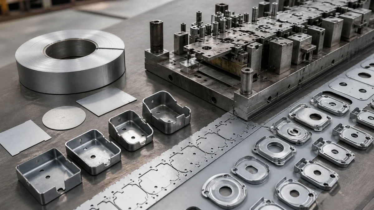
Material behavior changes throughout a multi-station sequence. Piercing removes supporting material, bending redirects deformation, coining applies concentrated pressure, and drawing moves material into a three-dimensional form. After each operation, the developing work must still be located, supported, and transported.
For a progressive concept, determine whether the carrier retains enough strength after nearby holes, notches, and forms are introduced. Narrow connections may stretch or distort, while strip camber may disturb progression through later stations. Grain direction can affect bending response and springback. Springback is the partial elastic return after forming pressure is removed; if it changes a flange angle or final profile, the tooling and inspection plan must address it.
Transfer tooling removes the continuous carrier, but not the material-handling problem. A thin blank may sag during pickup. An asymmetrical intermediate form may become difficult to retain. A tall feature may eliminate a gripping surface used at an earlier station, so transfer feasibility must be checked at every stage.
A useful material review covers:
- Exact grade, sheet thickness, temper, or supplied condition
- Grain direction and required orientation within the blank
- Cutting, bending, coining, embossing, and drawing by station
- Regions that lose stiffness after material removal
- Surfaces available for transfer pickup and retention
- Final flatness, surface finish, edge condition, and burr direction
Avoid generic labels such as “steel” or “aluminum.” The actual grade and condition are needed to evaluate forming response, carrier behavior, blank stiffness, tooling risk, and acceptance criteria.
Does the Part Geometry Favor Progressive or Transfer Tooling?
Progressive tooling may fit smaller, flatter geometry that can be pierced and formed while supported by a carrier. Transfer tooling may fit deep draws, tall flanges, large formed walls, multi-face operations, or parts requiring rotation, flipping, re-striking, cam piercing, or greater station clearance.
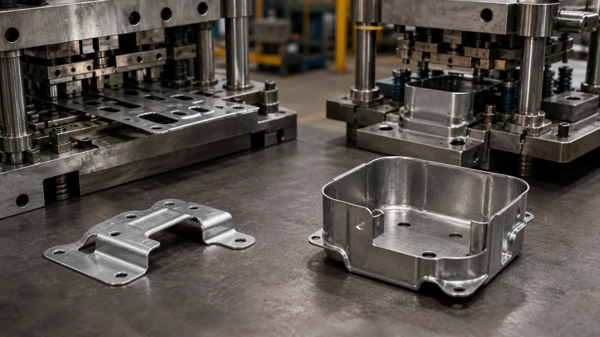
Geometry is a feasibility gate1 because the developing part must fit within a workable sequence, not merely inside the press. Classify every feature by how it is produced, how much material it moves, what tool access it needs, and how the work remains supported afterward.
| Geometry or operation | Progressive tendency | Transfer tendency | Critical review point |
|---|---|---|---|
| Repeated holes and cutouts | Often compatible | Also possible | Carrier strength after piercing |
| Tabs, shallow bends, embosses | Often compatible | Possible | Station spacing and springback |
| Coined areas | May fit an integrated sequence | May use dedicated stations | Force, location, and nearby distortion |
| Deep draws or tall flanges | Carrier may restrict material flow | Often more practical | Forming clearance and part release |
| Multi-face piercing | Tool access may be difficult | Reorientation may improve access | Datum retention between stations |
| Re-striking or ironing | Space may be restricted | More open station arrangement | Support, wall condition, and release |
| Rotation or flipping | Usually conflicts with strip attachment | More naturally accommodated | Transfer grip and orientation |
A flat pattern does not reveal every manufacturing constraint. The finished 3D model should show Z-height, draw depth, wall geometry, obstructed faces, and features created after forming. The controlled drawing should identify critical feature relationships, burr direction, cosmetic faces, and dimensions accepted in the final formed condition.
Scenario: A shallow electrical bracket has several holes, two tabs, and modest bends. Its geometry may progress through a carrier-based tool. If the design gains a tall drawn wall and a side feature that must be pierced afterward, transfer tooling may provide the necessary access and independent positioning. This is a teaching scenario, not a production case.
Which Handling Risk Is More Manageable for the Part?
Select the route whose handling problem can be controlled more reliably: carrier strength and strip location in progressive stamping, or blank pickup, lift, placement, retention, and timing in transfer stamping. Thin, flexible, asymmetrical, or heavily formed parts require particular handling review.
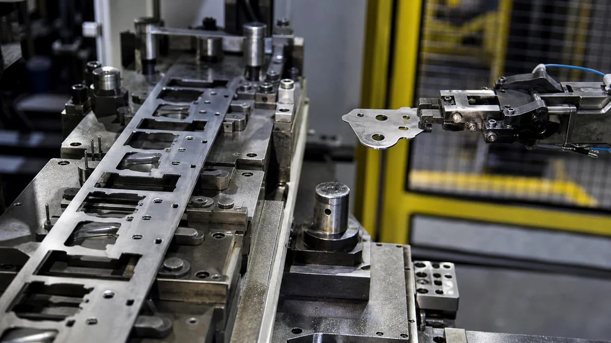
A formable part can still be a poor production candidate if it cannot be transported consistently. Progressive and transfer tooling solve this problem differently, so the handling review must follow every intermediate shape rather than only the finished part.
In a progressive die, the carrier is a functional part of the tooling concept. It must withstand feed acceleration, piloting, piercing, bending, and material flow while holding each developing part in the required relationship to later stations. Hole-to-edge relationships may weaken the web. An early form may pull the strip sideways. Strip camber2—the tendency of the strip to curve away from a straight feed path—can disturb station registration. Final cutoff must also release the part without damaging a controlled edge or cosmetic face.
Transfer tooling replaces carrier risk with coordinated movement. Transfer fingers or other handling elements need repeatable pickup locations. The part must clear the die during lift, remain controlled during the shift, and enter the next station in the intended orientation. Every operation can change the available gripping area, center of mass, stiffness, and formed height.
What should the supplier explain before tooling approval?
Ask how the proposed sequence establishes location at each station, prevents incorrect placement, retains the work during forming, and protects delicate or cosmetic areas. Mark surfaces that cannot accept contact and features that must remain free for pickup.
An asymmetrical blank may be stable at the first transfer station but lose a gripping area after a large cutout. In a progressive layout, postponing that cutout could preserve carrier strength. The sequence should resolve the handling issue deliberately instead of leaving it to press setup.
Which Tolerances and Inspection Results Must Apply to the Finished Stamping?
Apply close tolerances and documented inspection to features that control assembly or function, not automatically to the entire stamping. Define acceptance after forming, separation, deburring, finishing, and secondary work so suppliers measure the delivered condition rather than an intermediate blank.
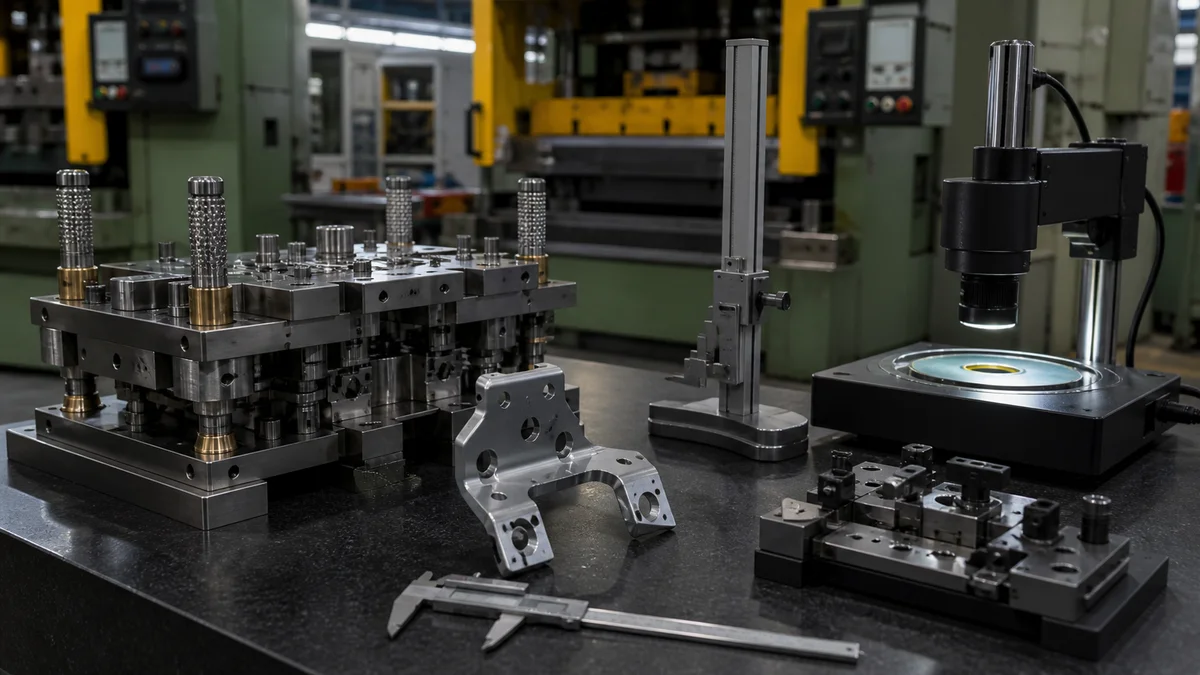
Neither process name establishes a universal tolerance. Progressive results may be influenced by strip location, pilot relationships, material flow, carrier stability, springback, and tool condition. Transfer results may also reflect blank placement, die-to-die alignment, retention, intermediate distortion, and transfer timing.
Begin with functional datums. A datum is a reference feature used to locate or orient other controlled characteristics. Then separate acceptance-critical features from clearance or cosmetic geometry. The drawing may need to control:
- Hole position relative to finished-part datums
- Relationships between pierced and formed features
- Mating edges and assembly interfaces
- Flange location or profile after forming
- Final flatness and springback-sensitive dimensions
- Burr direction and permitted edge condition
- Cosmetic faces and contact-mark restrictions
- Dimensions affected by plating, coating, deburring, or secondary machining
State whether each important dimension applies before or after finishing. Finish buildup can change a close fit, while deburring can alter an edge used for acceptance. A measurement on the flat blank also cannot replace verification of a hole positioned relative to a formed flange. These relationships can accumulate into tolerance stack-up across multiple operations, so the governing datum structure must match the delivered part.
Define the inspection method by characteristic rather than naming one instrument for the whole part. Accessible independent sizes may suit hand gauges; datum-related position or profile may require coordinate-based measurement; visible two-dimensional edges may permit optical inspection. Specify first-article results, selected dimensional reports, sampling, or continuing checks only where required.
Common specification mistake: Applying one close tolerance to every hole, profile, and bend. Localized controls focus tooling and inspection effort on the features that actually govern fit or function.
Can Progressive Throughput Be Achieved Without Compromising Geometry?
Use progressive tooling’s throughput advantage only after confirming that the carrier, station spacing, draw depth, support, and release are stable. High annual demand does not justify forcing geometry into a strip-fed process that cannot produce the required form and acceptance characteristics reliably.
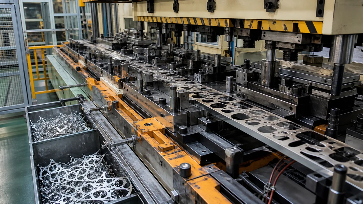
Progressive tooling reduces separate handling because one strip advances through an integrated station sequence. That principle can support efficient repeat production when the material, geometry, carrier, station spacing, and release arrangement are compatible. Transfer tooling adds lift, shift, and placement motion, but those steps may be necessary to produce the geometry without restricting material flow or tool access.
Evaluate throughput as acceptable finished parts over the required production period, not simply as press strokes. A progressive proposal built around fragile carriers, crowded stations, restricted forming depth, difficult scrap evacuation, or unreliable cutoff may not deliver its expected advantage. A transfer proposal involves more coordinated handling yet may provide a more stable route for deep drawing, re-striking, multi-face operations, or blank reorientation.
Does annual demand decide the tooling strategy?
Annual demand is an economic input3, not a geometry override. It helps determine whether dedicated tooling deserves evaluation and how tooling cost may be distributed across the expected program. The comparison must also include lot size, program duration, forecast confidence, material use, secondary operations, inspection scope, and revision risk.
Scenario: Procurement expects strong repeat demand for a part with a deep wall and a side feature created after drawing. Selecting progressive tooling solely for anticipated output could force compromised support or impractical station spacing. A transfer concept may involve more motion but provide a clearer forming and access plan. This is a process-selection example, not a claim about a specific production program.
Ask each supplier to state the assumed station sequence, feed or transfer arrangement, secondary operations, inspection scope, and sample-approval basis behind the quotation.
Which Tooling Strategy Has the Lower Total Program Cost?
Compare complete program economics rather than tooling price, material yield, or recurring piece price in isolation. Progressive tooling may reduce recurring handling for strip-compatible parts, while transfer tooling may add mechanism and alignment costs but improve forming flexibility or material utilization.
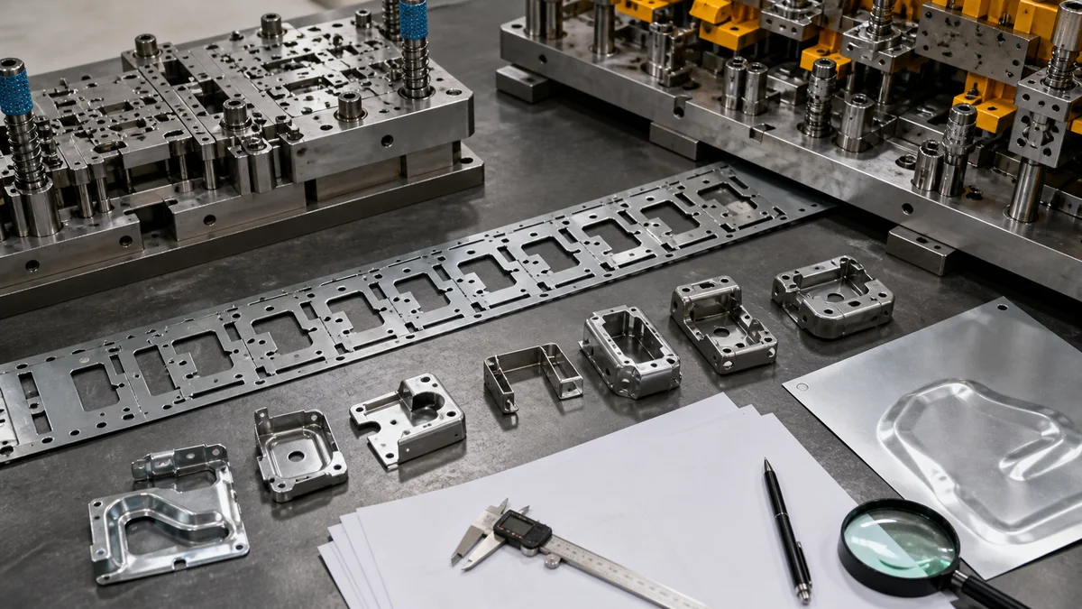
A sound commercial comparison separates one-time launch commitments from recurring delivered-part costs. Both proposals must use the same released material, revision, tolerances, surface finish, inspection scope, quantity tiers, and delivery assumptions.
| Quotation element | Progressive tooling review | Transfer tooling review |
|---|---|---|
| Tool design and build | Integrated strip layout and station sequence | Multiple dies and transfer arrangement |
| Tryout and samples | Feed, pilots, carrier, forms, scrap, and cutoff | Die matching, pickup, placement, retention, and timing |
| Material use | Carrier web plus blanking and forming scrap | No continuous carrier, but blanking scrap remains |
| Recurring processing | Continuous strip advancement may reduce handling | Transfer motion adds handling to the station sequence |
| Maintenance scope | Wear concentrated within an integrated die | Wear distributed across dies and transfer elements |
| Secondary work | Deburring, finishing, machining, or assembly | Equivalent delivered-scope operations |
| Inspection | Samples, reports, and continuing checks | Equivalent acceptance evidence |
Material utilization deserves close review when the specified alloy or sheet condition is a major cost driver. Better blank yield, however, does not automatically make transfer tooling less expensive. The program must also absorb transfer development, synchronization, setup, and maintenance. Likewise, a lower recurring progressive piece price cannot recover the tooling commitment if demand, design stability, or program duration falls short.
Request separate prices for die design and manufacture, tryout, initial samples, unit production, expected scrap, secondary work, inspection, packaging, and delivery. Define tooling ownership, storage, maintenance responsibility, engineering-change treatment, and replacement-component scope where they matter. Otherwise, apparently similar quotations may cover different commercial obligations.
Is the Design Stable Enough to Release Dedicated Tooling?
Release progressive or transfer tooling only when the controlled design, material thickness, critical forms, production forecast, and acceptance plan are sufficiently stable. Changes after release can affect strip layouts, station sequences, matched dies, transfer handling, tryout, samples, cost, and launch timing.
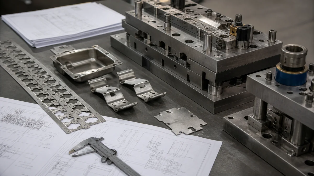
Dedicated tooling turns drawing decisions into physical stations and handling relationships. In a progressive die, changing a hole, profile, bend, material thickness, or formed detail may alter carrier strength, strip pitch, pilots, scrap flow, or station order. In transfer tooling, the same change may affect blank shape, die matching, pickup positions, clearance, orientation, or timing.
Use this tooling-release checklist4:
- Confirm that the active 3D model and controlled 2D drawing carry the same revision.
- Release the material grade, condition, sheet thickness, and grain-direction requirements.
- Identify functional datums, critical tolerances, and springback-sensitive forms.
- Define burr direction, cosmetic faces, contact restrictions, and final surface finish.
- Record unresolved technical risks and expected engineering changes.
- Provide immediate quantity, annual demand, lot sizes, forecast confidence, and program duration.
- Agree on sample approval, inspection method, continuing checks, and report expectations.
- Allow time for tool design, build, tryout, adjustment, and approval within the launch plan.
A pilot need does not necessarily justify releasing production tooling early. While geometry is unsettled, CNC turret punching or flexible sheet metal fabrication may provide a lower-commitment bridge when those routes can produce a useful interim part. Such parts must be labeled by validation purpose: they may confirm assembly or selected dimensions without reproducing final stamped material flow, springback, edge condition, or cosmetic appearance.
Moving a hole near a carrier boundary may appear minor but weaken the progressive web or change pilot strategy. In transfer tooling, shifting a tall flange may remove a planned pickup surface. Manufacturing-impact review should govern approval, not revision numbering alone.
How Should the Tooling Plan Address Strip Instability or Mis-Transfer?
Address the dominant failure mechanism before tooling release. Progressive plans should control strip camber, carrier weakness, location, and forming disturbance; transfer plans should control pickup, placement, retention, die alignment, clearance, orientation, and timing throughout every intermediate part condition.
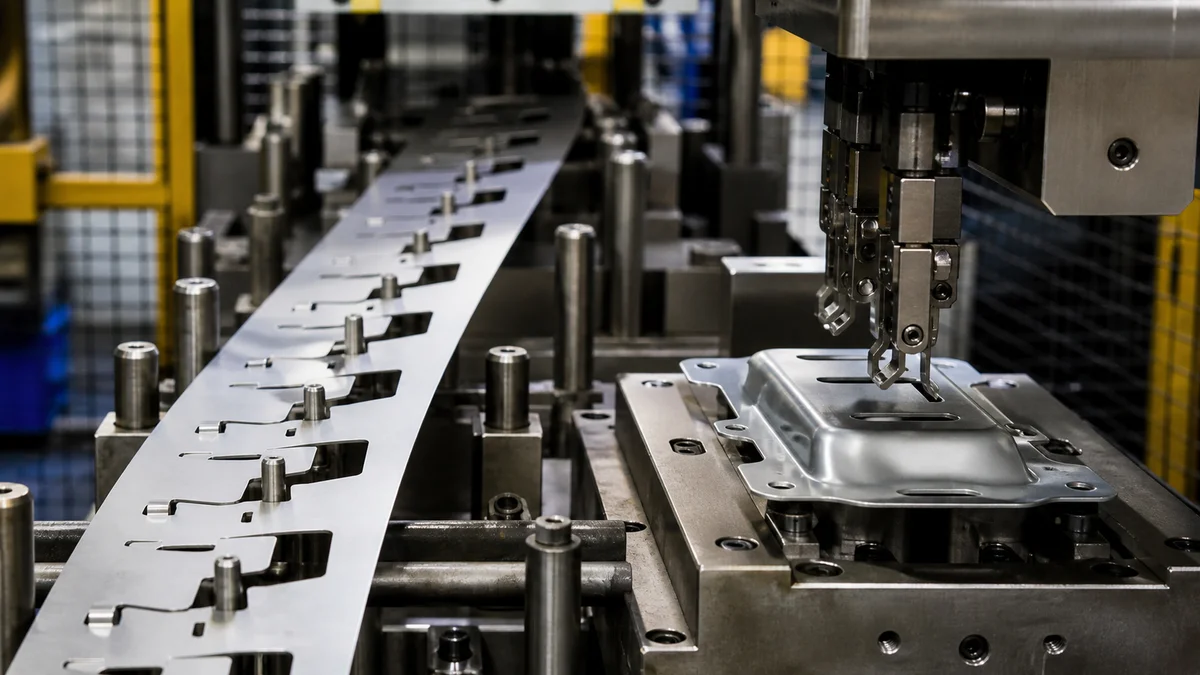
Failure prevention should begin with the expected mechanism, not a broad request for reliable tooling. Progressive instability and transfer mis-placement5 arise from different interactions among material, geometry, station sequence, and handling.
| Risk | Primary exposure | Specification evidence needed | Tooling review response |
|---|---|---|---|
| Strip camber | Progressive | Coil direction, strip layout, pitch, material condition | Review feed path and station progression |
| Weak carrier | Progressive | Piercing sequence, hole-to-edge relationships, forming load | Preserve or relocate supporting material |
| Forming-induced strip movement | Progressive | Bend, coin, emboss, and draw sequence | Reconsider station order and location strategy |
| Poor pickup | Transfer | Available contact areas and intermediate forms | Define stable pickup zones and restrictions |
| Mis-placement or rotation | Transfer | Orientation, locating features, and die entry | Provide positive location and placement control |
| Part loss during movement | Transfer | Blank stiffness, center of mass, and formed height | Review retention through lift and shift |
| Contact damage | Either | Cosmetic faces, delicate edges, and finish requirements | Define protected and permitted contact areas |
Show flatness targets, burr direction, edge condition, and critical positional relationships on the controlled drawing. A cosmetic face should not become an unplanned carrier contact or transfer pickup surface. A delicate flange should not be treated as a retention feature without review of its stiffness and final acceptance condition.
Common specification mistake: Providing only the finished solid model. It does not show which intermediate surfaces remain available for support, where pickup is prohibited, or which edge must preserve a specific condition. Add controlled notes or feature classifications so the supplier can develop the station and handling plan from explicit requirements rather than assumptions.
What Should a Progressive or Transfer Die Stamping RFQ Include?
Send enough information for suppliers to evaluate geometry, material behavior, tooling commitment, inspection, demand, and revision risk on consistent assumptions. A complete RFQ should define the part, delivered condition, production intent, expected demand, approval evidence, secondary work, and permission to propose alternative sheet metal routes.
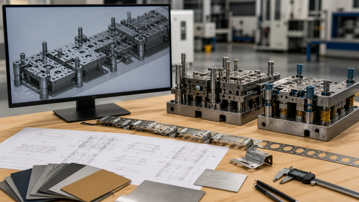
Use a controlled RFQ package rather than relying on a model and annual quantity alone. This stamping RFQ checklist6 supports a process-selection quotation.
Part definition
- 3D model and controlled 2D drawing
- Active revision and identification of the governing document
- Controlled flat pattern when one exists
- Functional datums and critical feature relationships
- Classification of holes, cutouts, bends, embosses, coined regions, draws, re-strikes, ironing, and secondary features
Material and delivered condition
- Exact material grade, sheet thickness, temper, or supplied condition
- Grain-direction requirements
- Burr direction and permitted edge condition
- Cosmetic face and surfaces with contact restrictions
- Surface finish, coating, deburring, cleaning, and other secondary operations
- Statement of whether critical dimensions apply before or after finishing
Demand and production intent
- Immediate quantity, annual demand, lot sizes, and expected program duration
- Prototype, pilot, bridge, or production intent
- Forecast confidence and known demand variation
- Expected design revisions or unresolved engineering risks
- Delivery expectations and launch priorities
Tolerance, inspection, and approval
- Critical tolerances, profiles, flatness, and formed-feature criteria
- Required first-article results or sample-approval process
- Inspection method or acceptance evidence for critical characteristics
- Ongoing sampling, dimensional reporting, or continuing production checks
- Final acceptance condition after stamping and secondary operations
Commercial and process scope
- Separate tooling, tryout, sample, unit-production, secondary-operation, inspection, and delivery pricing
- Tooling ownership, maintenance, storage, and engineering-change expectations where relevant
- Permission to propose progressive stamping, transfer stamping, CNC turret punching, or another sheet metal fabrication route when the engineering requirements allow alternatives
Complete information lets suppliers expose carrier, transfer, geometry, material, inspection, and tooling assumptions instead of burying them in quotation exceptions.
For a tooling recommendation, sample plan, or quotation, send the 3D model, controlled 2D drawing, material grade and thickness, quantity, prototype or production intent, critical tolerances, surface finish, inspection expectations, revision level, formed-feature requirements, forecast, and delivery expectations.
References
-
Deep Draw Metal Stamping - Holland - Deep-draw metal stamping is a high-speed, high-value, shape-transformation process that forms sheet metal into round, square, or irregular components. ↩
-
4 causes of poor strip feeding in progressive dies - Most stamping plants have experienced poor strip feeding in a progressive die ... Severe camber can cause poor feedability into a progressive die ... ↩
-
Progressive Sheet Metal Stamping for High-Volume Parts - Progressive stamping typically becomes cost-effective at annual volumes of 50,000 units or more, although very simple parts may justify tooling ... ↩
-
13 Mechanical Design Considerations for Metal Stamping Parts - Buyers should confirm part function, material, key dimensions, and annual volume before approving die design. ↩
-
3 best practices metal stampers can follow for transfer die ... - It is common in transfer dies to see two blanks run through together, inline front to back, with a temporary carrier strap holding them together ... ↩
-
How precise can sheet metal stamping processes be? - A useful RFQ includes a 2D drawing, 3D model, material grade, thickness, temper, coating, part volume, target process, critical dimensions, burr direction, ... ↩