
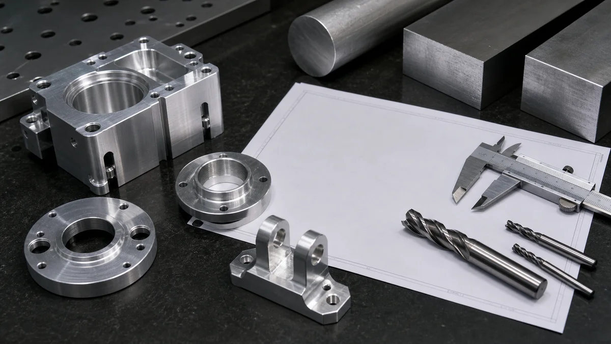
CNC machining cost is largely determined before cutting begins. Material grade, stock size, tool access, setup count, tolerance, surface finish, inspection scope, and order quantity all shape the manufacturing plan. A low quotation can therefore carry more technical or acceptance risk than a well-scoped quotation that reflects the part’s actual function.
Effective cost reduction removes requirements that do not support fit, sealing, alignment, appearance, or service performance. It does not mean relaxing every specification. The 3D model, controlled drawing, production plan, and RFQ must distinguish critical features from ordinary geometry.
The decisions below show where specifications create avoidable work and what information manufacturers need to recommend a more economical route without weakening functional requirements.
Is CNC Machining the Most Cost-Effective Process for Your Part?
CNC machining is cost-effective when a part needs material removal, accessible precision features, limited tooling commitment, or design flexibility. The final choice depends on material, geometry, tolerance, quantity, design stability, inspection level, and whether a sheet metal, stamping, casting, or molding process fits better.
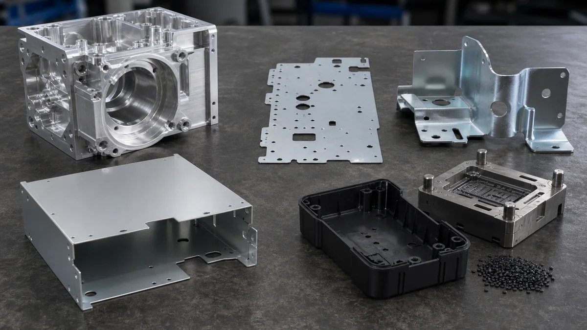
CNC machining creates geometry by removing material through milling, turning, drilling, boring, reaming, and related operations. It can suit prototypes, changing designs, specified wrought materials, and parts with precision interfaces. Unlike die-based or mold-based production, it does not inherently require dedicated production tooling.
Compare processes by their operating principles and specification needs:
| Process | How it forms the part | Specification issues to review |
|---|---|---|
| CNC machining | Removes material from bar, plate, billet, or another workpiece | Cutter access, setup count, tolerance, surface finish, inspection |
| CNC turret punching or CNC punch press | Uses programmed punch tools on sheet metal | Sheet thickness, available tooling, hole geometry, burr direction |
| Metal stamping | Cuts or forms sheet with dedicated dies | Tooling risk, burr direction, springback, stable production volume |
| Sheet metal fabrication | Combines operations such as cutting, punching, bending, welding, and finishing | Bend geometry, springback, joints, weld distortion, finish |
| Plastic injection molding1 | Injects polymer into a mold | Wall thickness, draft, gate location, shrinkage, tooling commitment |
“CNC turret punching, CNC punch press, CNC-controlled stamping equipment, or metal stamping depending on the actual process” is not a standard process term. An RFQ using that phrase should clarify whether it means CNC turret punching, a CNC punch press, CNC-controlled stamping equipment, or general metal stamping. The distinction affects both the quotation and the drawing requirements.
Scenario: Machined housing before tooling. A developing aluminum housing may be CNC machined while its interfaces and fastening features are changing. If the design may later move to die casting or Plastic injection molding, review wall thickness, corner radii, draft, fastening geometry, cosmetic surfaces, and possible gate location before tooling. This is a teaching scenario, not a reported customer case.
Which Materials, Stock Sizes, and Standard Features Lower Machining Cost?
Lower-cost specifications use an available material grade and condition, a practical stock form, and standard feature sizes wherever function permits. These choices can reduce sourcing uncertainty, excess stock removal, special tooling, and tool changes without weakening required mechanical, environmental, finishing, or documentation requirements.
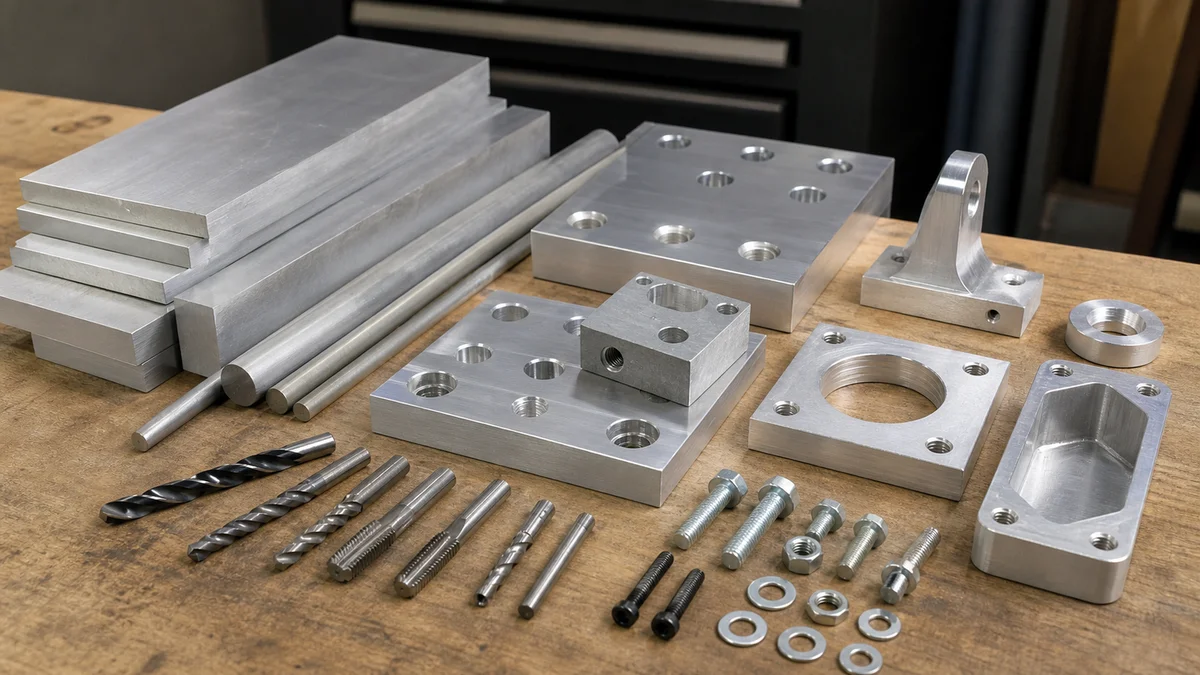
Name the material grade and condition instead of requesting only “aluminum,” “steel,” or “plastic.” The manufacturer needs this information to assess machinability, sourcing, tool wear, distortion risk, finishing response, and material documentation. Any alternative grade should be reviewed against the properties and environmental conditions that matter to the design.
Blank selection is equally important. A part envelope that works with common bar, plate, or billet dimensions may require less preparation and stock removal than one that forces a custom blank or a large machining allowance. Buyers do not need to dictate the exact blank, but the RFQ can permit a proposal based on standard stock forms2.
Review these standardization opportunities prior to drawing release:
- Use standard drill diameters where assembly clearance permits.
- Select standard thread forms, sizes, and practical engagement lengths.
- Reuse common hole, radius, chamfer, and counterbore sizes.
- Choose off-the-shelf fasteners and inserts where they meet assembly needs.
- Remove non-functional engraving, text, or decorative micro-features.
- Separate mandatory material properties from preferences.
- State whether equivalent materials or feature sizes require written approval.
A useful design-for-manufacturing review compares the modeled feature with available cutting tools and stock while preserving fit-critical dimensions. For example, a nearby standard drill size may satisfy a clearance-hole function without changing its true-position requirement.
Standardization is not permission for uncontrolled substitution. Material grade, temper or condition, corrosion behavior, coating response, strength, service temperature, and required records remain buyer-controlled specifications.
How Should You Specify Internal Corners for Lower-Cost Milling?
Specify the largest internal corner radius that preserves fit and clearance because cylindrical milling cutters cannot create perfectly sharp internal corners directly. Larger, consistent radii permit more rigid cutters; small or varying radii can require extra tools, slower passes, local cleanup, or a different manufacturing approach.
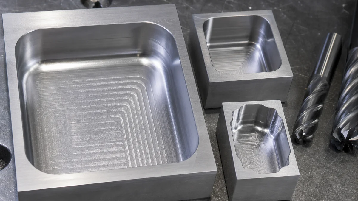
An end mill leaves an internal radius related to its cutter size. When a pocket has a very small radius, the manufacturer may need a smaller, less rigid tool with lower material-removal capability. Cutter engagement3 also rises as the tool enters a tight corner, affecting vibration, finish, and toolpath planning.
A radius of at least one-third of cavity depth is a useful cost-oriented design target from the supplied research, not a universal manufacturing limit. Suitability still depends on material, pocket width, opening size, tool reach, tolerance, and surface finish. Repeating one practical radius across several internal edges may also reduce tool changes.
Does the mating part really require a sharp corner?
Often it does not. A rectangular mating component may fit with corner reliefs, dog-bone-style clearance, a chamfer on the mating part, or a revised contact zone. The drawing should identify the surfaces that locate the assembly and distinguish them from corners that provide clearance only.
Example: Near-sharp CAD pocket. A pocket retains near-sharp corners because its modeled appearance was never checked against cutter access. The quotation must then include small-tool machining or pause until permitted relief is clarified. Defining the mating envelope and acceptable corner relief prior to quotation removes that uncertainty.
Do not enlarge every radius automatically. Sealing geometry, adjacent holes, material thickness, or required contact area may constrain a corner. Where a near-sharp corner is functional, state its purpose and allowable relief so alternative methods can be evaluated against explicit acceptance criteria.
When Do Deep Pockets and Holes Become Major Cost Drivers?
Deep pockets and holes become major cost drivers when tool reach, chip evacuation, deflection, vibration, or inspection access requires special tooling and conservative cutting. Keep depth proportional to cutter or hole diameter where function permits, and classify unavoidable deep features as precision, clearance, or cosmetic geometry.
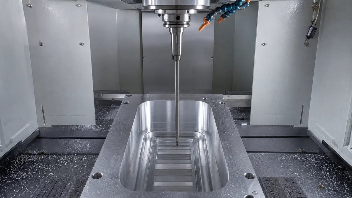
Depth alone does not determine machining difficulty. The machining plan must also consider the smallest internal radius, pocket width, opening size, material, wall finish, bottom geometry, tolerance, and chip-clearing path. A deep open pocket may be easier to machine than a shallower cavity reached through a narrow opening.
Use the following ratios as screening points, not capability guarantees:
| Feature | Cost-oriented review point | Practical consequence outside the range |
|---|---|---|
| Cavity depth | About two to three cutter diameters is favorable | Longer tools may deflect or require lighter passes |
| Hole depth | About four hole diameters is a practical target | Peck drilling, longer tooling, or improved chip evacuation may be needed |
| Narrow slot | Compare width, depth, and end radius together | A small extended cutter may limit rigidity |
| Deep finished wall | Identify the actual controlled area | Finish passes and inspection access may expand |
Geometry, material, machine access, tooling strategy, tolerance, and required finish can shift each practical range. The table is therefore a DFM screen rather than a pass-or-fail rule.
For an unavoidable deep feature, mark the critical surfaces on the controlled 2D drawing. State whether the floor must be flat, whether a drill-point form is acceptable, and whether the full wall depth needs controlled roughness. Also identify any section that exists only for clearance or appearance.
This detail supports selection of an appropriate deep-hole machining strategy4 or pocketing approach without assuming precision throughout. It also exposes features that could be shortened, widened, opened from another direction, or removed before the machining plan is fixed.
How Can Wall, Rib, and Thread Specifications Prevent Unnecessary Machining Cost?
Use wall thicknesses, rib proportions, and thread lengths that satisfy function without creating unstable cutting conditions. Thin walls, tall ribs, and unnecessarily deep threads can require lighter passes, careful workholding, greater tool reach, and additional inspection because the material may deflect, vibrate, or distort.
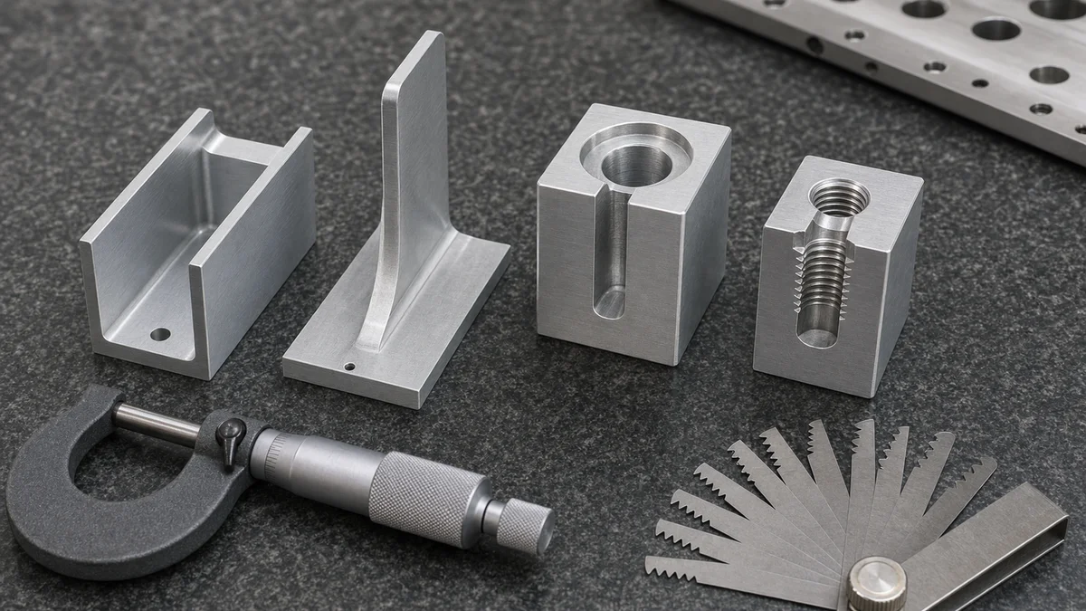
A wall that is rigid in the assembled product may remain flexible during machining. Cutting force, residual stress, clamping, and heat can move a thin section while surrounding material is removed. The result may be chatter, variable thickness, poor finish, or dimensional change after unclamping. Risk depends on material, unsupported height, adjacent geometry, cutter access, and tolerance—not wall thickness alone.
Review each feature by function:
- Walls: Does the wall provide sealing, stiffness, shielding, or simply close a pocket? Could local support or a different pocket layout preserve its purpose?
- Ribs: Is the full rib height necessary, and can a cutter reach both sides without excessive extension?
- Threads: What usable engagement does the joint require? Roughly three times the hole diameter is a useful upper review point where the application permits.
- Blind holes: Is there room beyond the full thread for tool lead, runout, and unthreaded relief?
- Inspection: Can the specified inspection method reach the wall, rib, or thread characteristic?
Calling for full-form thread to the bottom of a blind hole is a common specification error. A tap or thread mill needs practical runout, and drill-point geometry also consumes depth. Define usable thread engagement5 separately from total drilled depth.
When a thin wall or tall rib is unavoidable, identify its datum relationship and functional surface. Do not compensate with a blanket profile tolerance. Require a review of workholding, cutting sequence, and measurement condition for the actual material and quantity. That produces a more meaningful risk assessment than applying one minimum-wall rule to every part.
Can Fewer Setups or a Multi-Part Design Reduce Machining Cost?
Fewer setups can reduce programming, workholding, alignment, datum transfer, and inspection effort when critical features remain accessible. Dividing a complex part into simpler components may also help, but assembly hardware, joining, tolerance stack-up, sealing, strength, and final inspection must be included in the comparison.
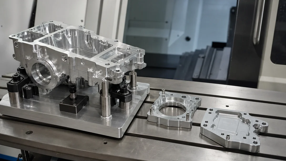
A setup involves more than turning the workpiece over. Each orientation may require locating, clamping, alignment, tool clearance, another machining sequence, and confirmation that datums transfer correctly. Features cut from one stable orientation are generally easier to control relative to each other than features split across several setups.
| Design route | Likely machining effect | Specification risk to check |
|---|---|---|
| One primary access direction | Fewer workholding and datum-transfer steps | Hidden features or excessive tool reach |
| Several machined sides | Direct access to multi-side geometry | Cross-setup face-to-bore or hole-pattern relationships |
| Indexed or multi-axis access | Less manual repositioning may be possible | Programming, collision clearance, and measurement access |
| Multiple simple components | Easier individual tool access | Joining, sealing, strength, and tolerance stack-up |
The fewest setups do not automatically produce the best part. Another orientation may be necessary to create a bore, sealing face, or hole pattern correctly. The controlled drawing should use functional datums to define these relationships instead of assuming a particular machining sequence.
A multi-part redesign needs a full cost and specification review. Include fasteners, dowels, inserts, joint preparation, assembly effort, sealing, stiffness, and accumulated positional error. If welding is proposed, account for possible distortion and any required post-joining machining or finishing.
When geometry allows, request a comparison between the original configuration and a reduced-setup or multi-component option. Provide assembly loads, allowable joint types, sealing requirements, critical feature relationships, and production intent. This keeps the decision focused on total manufactured cost rather than cycle time alone.
Which Features Actually Need Tight Tolerances and GD&T?
Reserve tight tolerances and GD&T for features that control fit, sealing, alignment, motion, or assembly. Apply general or looser requirements to non-critical geometry, and establish clear datums when feature relationships matter. This concentrates machining, process control, and inspection on dimensions that determine acceptance.
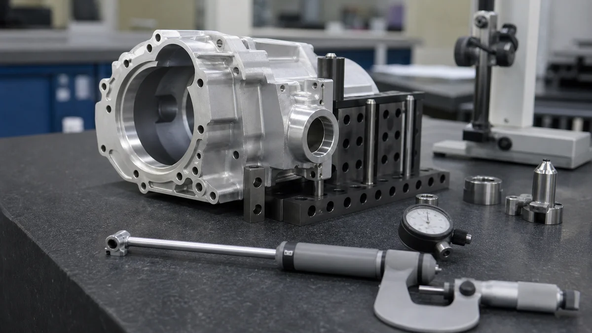
Begin tolerance selection with feature function. Bearing bores, sealing faces, dowel holes, press fits, mating planes, and alignment features may need close control. Clearance pockets, lightening cuts, cosmetic edges, and non-contact faces often do not.
For many non-critical aluminum features, a general tolerance around ±0.10 mm to ±0.13 mm can be a practical quoting baseline when tighter control is unnecessary. This remains dependent on manufacturing capability, geometry, material, feature size, setup, and inspection method. Put general tolerances in the drawing notes or title block, potentially by referencing an applicable standard such as ISO 2768, instead of repeating them on every dimension.
| Feature class | Appropriate specification focus | Approval question |
|---|---|---|
| Functional interface | Size plus necessary geometric relationship | What failure does the limit prevent? |
| Assembly feature | Clearance, fit, or position to assembly datums | Which surfaces establish the assembly? |
| Non-critical geometry | General or looser tolerance | Does it need separate inspection? |
| Cosmetic feature | Local dimensions and appearance criteria | Does it affect fit or presentation only? |
A feature below about ±0.05 mm should be treated as a machining and inspection decision. Fixturing stability, tool wear, machine warmup, cutter compensation, thermal conditions, and measurement method may become relevant. Confirm that the actual geometry and quantity support repeatable control prior to releasing the limit.
Use geometric dimensioning and tolerancing6 when size alone does not express function. Flatness, parallelism, perpendicularity, true position, coaxiality, and profile can define relationships clearly when datums and inspection expectations are unambiguous. Tightening every coordinate dimension is a poor substitute for locating a functional hole pattern to its mating datums.
Where Should Fine Surface Finish Requirements Apply?
Apply fine surface finish requirements only where controlled roughness supports sealing, sliding, bearing, coating preparation, or defined appearance. Localized callouts let ordinary surfaces retain a normal machined condition and prevent unnecessary finishing passes, secondary operations, masking, finish-sensitive tolerance work, and roughness inspection.
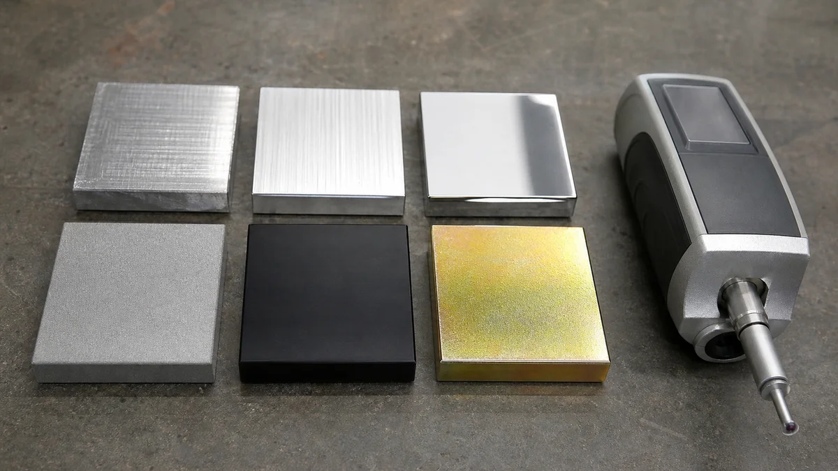
Surface finish is a functional specification, not a general request for smooth-looking parts. In CNC machining, roughness values such as Ra are influenced by tool condition, feed, step-over, cutting direction, toolpath, material, and finishing passes. A finer requirement can change both machining strategy and verification effort.
The supplied research identifies Ra 3.2 micrometers as a common economical reference and Ra 1.6 to 3.2 micrometers as a practical range for many commercial machined parts. These values are not universal defaults. A sealing face, bearing journal, sliding area, visible face, and coating-preparation surface may each need a different condition.
Complete this drawing review prior to release:
- Mark the exact surfaces that require a controlled Ra value.
- Separate functional roughness from cosmetic appearance.
- Define appearance with controlled notes or an approved sample when needed.
- Specify grinding, lapping, polishing, bead blasting, anodizing, or plating by location.
- Identify masking zones and surfaces that must remain uncoated or unpolished.
- State whether dimensions apply before or after finishing.
- Identify surfaces requiring measured and reported roughness.
- Define deburring, edge breaks, and chamfers where they affect handling or assembly.
A blanket fine-finish note can force slower passes and wider inspection even when only one sealing surface is critical. Local surface finish symbols make the intended manufacturing scope clearer.
Applied coatings may create finish buildup7 and alter final dimensions. Review tolerance-critical holes, threads, mating faces, and masked areas together with the finish specification. Otherwise, machining and finishing operations may use different assumptions about final acceptance.
What Inspection Scope Is Proportionate to Part Risk?
Inspection is proportionate when its method, frequency, and documentation match feature function, tolerance, geometry, quantity, and failure risk. Identify critical characteristics and required evidence before quotation instead of demanding complete reports for every model dimension or leaving the manufacturer to infer the acceptance plan.
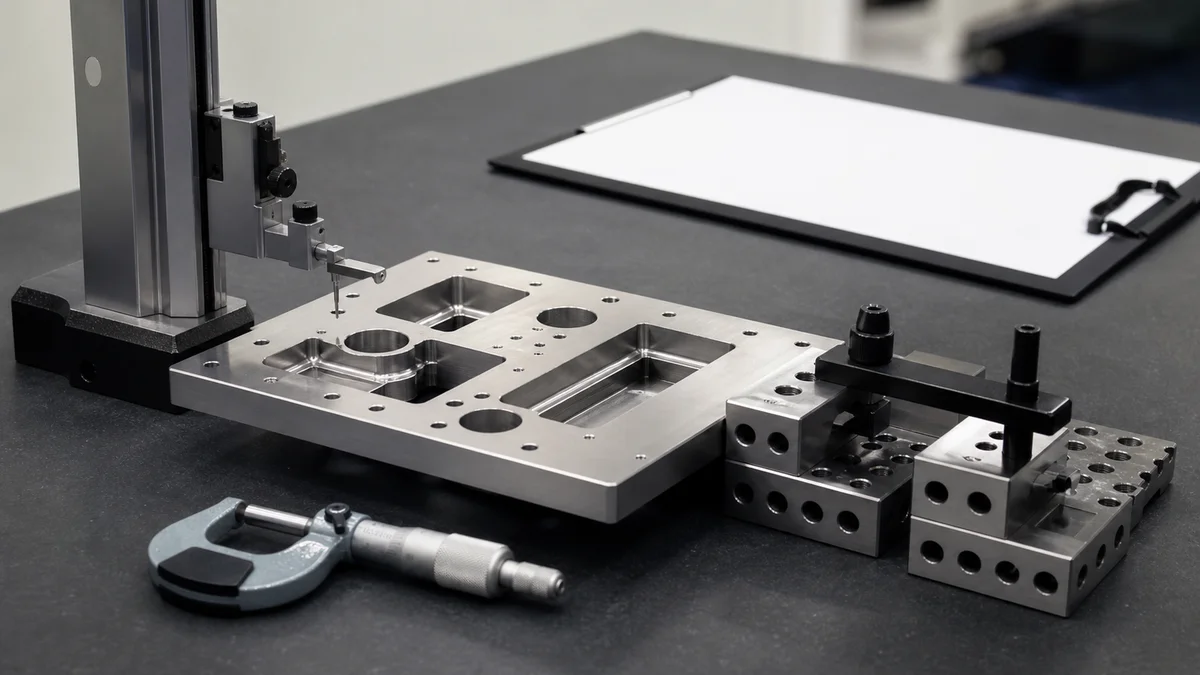
Inspection adds value when it confirms a defined requirement. It adds avoidable effort when every model dimension is treated as equally critical or when reports are requested without an acceptance purpose. Connect each required check to a drawing characteristic, datum, finish zone, or material requirement.
| Feature or approval need | Suitable scope to consider | Information required in the RFQ |
|---|---|---|
| Initial process approval | First article inspection of selected characteristics | Approval features, drawing revision, required report |
| Process monitoring | In-process checks on risk-sensitive dimensions | Feature, frequency, and response to a nonconforming result |
| Batch acceptance | Sampling or selected full inspection | Characteristics, sampling basis, acceptance criteria |
| Delivery evidence | Final dimensional or material records | Required document and traceable part revision |
| Surface verification | Visual standard or roughness reading | Surface location, Ra requirement, measurement direction |
The inspection method should fit the characteristic. Accessible sizes may suit hand measurement, while flatness, position, profile, coaxiality, or a tight hole pattern may require structured measurement. Avoid naming a device as a quality shortcut without first considering geometry, tolerance, datum access, and the evidence needed.
When is full inspection appropriate?
Selected 100 percent inspection may be justified for a critical feature with a defined functional or contractual risk. It should identify the exact characteristic and any record that must be retained or delivered; it should not be a blanket signal of quality.
Aluminum thermal movement8 can affect tight dimensions across larger spans and precision interfaces. If acceptance depends on a reference temperature or a particular part state, include that condition in the drawing or RFQ so both parties evaluate the feature consistently.
How Should Order Quantity and Production Intent Shape the Quote?
State whether the order supports design learning, functional validation, pilot production, or stable repeat production, then request realistic quantity tiers. Programming, setup, fixturing, material purchasing, batching, and inspection planning change with production intent, so lower unit cost alone does not justify buying revision-sensitive parts.
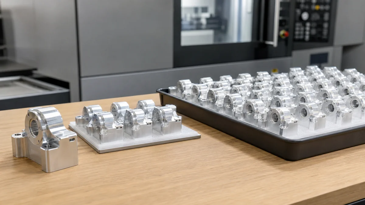
A one-off prototype and a repeat low-volume order may share geometry but need different manufacturing plans. A learning prototype can prioritize design feedback and inspection of essential interfaces. A pilot batch may need repeatable workholding, controlled finishing, and formal approval records. Stable repeat production may justify more preparation for toolpath efficiency, batching, and material supply.
| Production intent | Primary objective | RFQ information that changes the plan |
|---|---|---|
| Design-learning prototype | Evaluate geometry or assembly | Immediate quantity, expected changes, essential features |
| Functional validation | Test defined interfaces or performance | Material, critical tolerances, finish, inspection evidence |
| Pilot production | Confirm repeatability and release readiness | Batch size, revision status, approval plan, reporting |
| Repeat production | Support continuing demand | Order quantity, projected usage, delivery pattern, change control |
Programming, setup, and fixturing are non-recurring efforts that can be distributed across more parts. Higher quantities may support batching, multi-part workholding, or different material purchasing. They do not guarantee a specific cost curve, fixture strategy, or manufacturing route.
Scenario: Quantity before design freeze. A larger batch may show a lower quoted unit price while a mounting interface is still changing. If that interface is revised, unused parts can outweigh the apparent unit saving. Request tiers that reflect likely prototype, pilot, and production needs, then compare revision exposure as well as price.
State whether partial shipments are acceptable, whether demand is recurring, and whether later lots must remain interchangeable with the initial batch. If projected annual usage9 is uncertain, label it as a forecast rather than a commitment. Clear production intent supports appropriate workholding and inspection planning without overbuilding the prototype process.
What Should a Cost-Ready CNC Machining RFQ Include?
A cost-ready RFQ defines the part, material, quantity, production intent, critical features, finish, inspection evidence, revision, and delivery expectations while allowing bounded DFM feedback. Controlled information reduces contingency assumptions and helps manufacturers evaluate stock, tooling, setups, secondary operations, and acceptance on the same basis.
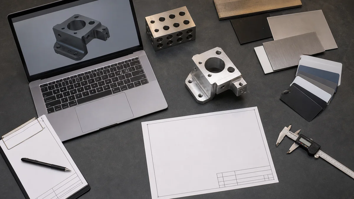
A 3D model communicates geometry but rarely defines every acceptance requirement. The controlled 2D drawing should identify tolerances, datums, GD&T, surface finish zones, threads, edge conditions, secondary operations, and inspection expectations. Model and drawing revisions must agree.
Use this CNC machining RFQ checklist10 prior to requesting a quotation:
- ☐ Native or neutral 3D model representing the intended geometry
- ☐ Controlled 2D drawing with matching part number and revision
- ☐ Material grade, temper, condition, or polymer specification as applicable
- ☐ Immediate quantity and realistic quotation tiers
- ☐ Prototype, validation, pilot, or repeat-production intent
- ☐ Functional, assembly, cosmetic, and non-critical features identified
- ☐ Critical size tolerances and applicable general tolerance note
- ☐ GD&T controls with clear functional datums
- ☐ Surface roughness values assigned to specific surfaces
- ☐ Coating, masking, polishing, grinding, marking, or other secondary operations
- ☐ Deburring, edge-break, and chamfer requirements where necessary
- ☐ Dimensions identified as applying before or after finishing
- ☐ First article, sampling, final inspection, and reporting expectations
- ☐ Material or finish documentation requirements
- ☐ Drawing standard and acceptance method where applicable
- ☐ Delivery expectations and partial-shipment permission
- ☐ Acceptable material, stock, or geometry alternatives clearly bounded
- ☐ Permission for manufacturing DFM feedback before production release
Avoid prescribing feeds, speeds, tool brands, or a detailed machining sequence unless the process itself is controlled. Specify the required final characteristics and explain why unusually difficult features matter.
Require the quotation to list assumptions involving stock selection, cutter access, setup count, thin walls, deep features, tooling, tolerance, finish, and inspection. Resolve them through a revised quotation or documented release before work begins. This makes comparisons more meaningful by exposing hidden differences in manufacturing and acceptance scope.
For a process recommendation or quotation, send the 3D model, controlled 2D drawing, material grade and condition, quantity, prototype or production intent, critical tolerances, surface finish, inspection expectations, revision level, and delivery requirements. Identify the features that control fit, sealing, alignment, or appearance so DFM changes remain functionally safe.
References
-
PLASTIC PART DESIGN FOR INJECTION MOLDING - Wall Thickness: Uniform wall thickness is crucial to avoid defects like warping or sink marks. Designers aim for consistent thickness, typically between 1.5mm ... ↩
-
Bar vs Plate Stock – Differences for CNC Machining | Bang Design - Bar and plate represent two fundamental forms of metal stock material used throughout manufacturing. The distinction between them goes beyond simple. ↩
-
How Corner Radius Affects CNC Machining - Protocase Blog - The gif shows two different corner radii. The red line indicates the tool path, and the yellow highlighted area indicates tool engagement. In ... ↩
-
Deep Hole Drilling Control - SME.org - With this fine-grained control, operators can adjust the feedrate and spindle speed to address issues like chip management and the straightness ... ↩
-
Blind Hole Tapping Guide: Machine Blind Holes in Engineering - This blind hole tapping guide breaks down what engineers, buyers, and machinists must understand before specifying or producing blind threaded holes. ↩
-
The ASME Y14.5 GD&T Standard - Depending on the profile shape and datums referenced, profile tolerances can control size, form, orientation, and/or location. The ASME Y14.5 ... ↩
-
How Anodize Thickness Changes Your CAD Dimensions - RivCut - Total Coating Thickness = Penetration (50%) + Buildup (50%). This buildup is what changes your part dimensions. Let us look at a standard coating. If the ... ↩
-
Aluminum 6061-T6 (UNS AA96061) | NIST - Where: Coefficients a–i are summarized in the appropriate table and T is the temperature in K (x-axis), and y is the property to solve for. ↩
-
CNC Machining RFQ Template Guide - uneed - prototype RFQs emphasize speed and DFM feedback. A production RFQ usually needs clearer annual quantities, packaging needs, and quality expectations. ↩
-
CNC Machining RFQ Checklist: Get Faster, Accurate Quotes - Use this CNC machining RFQ checklist to send the right files, tolerances, materials, and inspection needs—so you get faster, ... ↩