
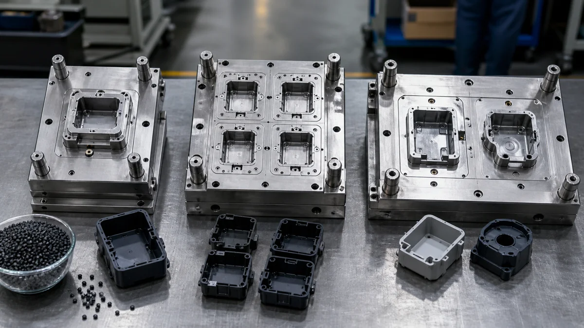
Choosing a mold configuration is not simply a tradeoff between tooling cost and output. The right strategy depends on what must leave the mold each cycle, how stable the design is, how the resin and geometry behave, and which features must remain consistent across production.
A single-cavity mold limits the initial tooling commitment. A multi-cavity mold increases output for one identical part. A family mold produces different related parts together, but only when those parts can share compatible molding conditions.
A sound decision therefore moves from cavity definitions to production intent, resin compatibility, geometry, inspection, total program economics, revision exposure, process balance, and a complete RFQ.
What Does Each Mold Strategy Produce per Cycle?
A single-cavity mold produces one part per injection cycle, a multi-cavity mold produces multiple identical parts, and a family mold produces different related parts together. Choose the definition that matches whether the program needs controlled development, higher output of one SKU, or synchronized production of several SKUs.
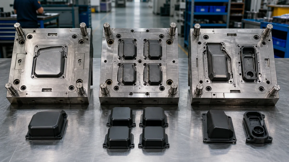
The cavity arrangement determines the physical output of each molding cycle. In plastic injection molding1, molten resin fills one or more mold cavities, cools into the required shapes, and is ejected. The number and identity of those shapes distinguish the three strategies.
| Mold strategy | Parts produced per cycle | Production purpose | Specification focus |
|---|---|---|---|
| Single-cavity | One | Limit initial tooling commitment | Control one part and one cavity |
| Multi-cavity | Multiple identical parts | Increase output of one stable SKU | Maintain cavity-to-cavity consistency |
| Family mold | Multiple different parts | Produce related SKUs together | Match resin, fill, cooling, and demand ratios |
A left housing and a right housing molded together form a family arrangement because the cavities produce different parts. Four identical covers made in one shot constitute a multi-cavity arrangement. This distinction affects tooling design, sample approval, inspection traceability, production output, and revision exposure.
These terms belong to plastic injection molding. CNC machining removes material from solid stock. CNC turret punching2 uses programmed physical punches to create sheet-metal features. Metal stamping cuts or forms sheet with dedicated dies. Broader sheet metal fabrication may combine cutting, punching, bending, hardware insertion, welding, and finishing.
“CNC turret punching, CNC punch press, CNC-controlled stamping equipment, or metal stamping depending on the actual process” is not one standard process term. An RFQ using that phrase should clarify whether it means CNC turret punching, a CNC punch press, CNC-controlled stamping equipment, or general metal stamping. None describes an injection mold cavity strategy.
Which Cavity Strategy Matches Your Production Intent?
Use a single-cavity mold when tooling exposure or design uncertainty is the main concern, a multi-cavity mold when stable demand supports greater output of one part, and a family mold when compatible related components must be produced in coordinated quantities. No universal volume threshold replaces a project-specific quotation.
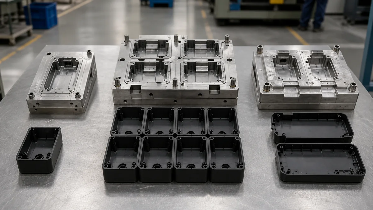
Begin with the program objective. Prototype learning, launch support, repeat production, and synchronized kit supply create different priorities even when the individual parts look straightforward.
Use these questions as an initial screen:
- Is the geometry released, or are wall thickness, draft, fastening features, and cosmetic surfaces still changing?
- What are the immediate quantity, annual demand, batch size, and expected program duration?
- Does the project need greater output of one SKU or matched quantities of several SKUs?
- Are related parts always ordered together, or could their demand ratios change?
- What sample approval and inspection work must occur before repeat production?
- Could mold size, shot requirements, or press availability restrict the proposed cavity count?
A single cavity may suit an evolving design because a revision is confined to one cavity. A multi-cavity tool may fit stable repeat demand when increased output justifies added tooling and validation. A family mold may suit parts consumed as a fixed set, but it is not merely a cheaper substitute for separate tools. The parts must also share compatible resin, filling, cooling, and ejection conditions.
Scenario: An assembly uses one upper housing and one lower housing, both in the same resin and color. A family mold deserves review if their geometries and processing windows3 align. If service demand later requires three upper housings for every lower housing, the fixed mold output can create inventory imbalance. Separate tools may provide better quantity control.
Treat published volume ranges as screening references. Part size, cycle conditions, design maturity, mold complexity, inspection scope, forecast confidence, and revision risk can all change the economic result.
Can the Parts Share the Same Resin and Processing Window?
Different parts should share a family mold only when their resin, color, wall geometry, flow behavior, cooling demand, and overall molding conditions are compatible. Identical-part multi-cavity tools avoid different-SKU compatibility problems, but they still require a runner and cooling design that supports balanced cavity performance.
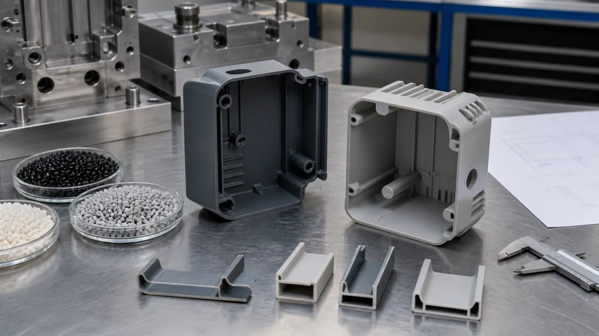
A molding process window4 is the range of conditions within which the specified resin and geometry can be filled, packed, cooled, and ejected acceptably. Family-mold parts occupy the same tool and share the overall cycle, so they cannot be managed as though each cavity had an independent process.
Evaluate these compatibility inputs when considering a family concept:
- Exact resin grade and permitted alternatives
- Color, additives, reinforcement, and cosmetic requirements
- Nominal walls and local wall-thickness changes
- Differences in part mass and flow length
- Thin regions, thick bosses, ribs, and abrupt transitions
- Gate restrictions and appearance-critical surfaces
- Cooling-sensitive sections likely to govern the cycle
- Draft, ejection needs, and delicate molded features
“Same plastic” is too broad for a tooling decision. Related resins or differently reinforced grades should not be assumed to require identical conditions. Even one resin and color do not prove compatibility: a small thin cover and a thick structural base may fill and cool differently.
An identical-part multi-cavity tool starts from more consistent geometry and material, but balance is not automatic. Runner length, gate position, cavity location, and cooling layout can still create cavity-to-cavity differences5. Material compatibility removes only one source of variation.
State fixed material requirements before the supplier develops the mold concept. If alternatives are allowed, identify the functional, appearance, and service requirements that must remain unchanged. This lets the molder review the actual resin grade with the part geometry rather than base the quotation on an undefined material family.
Does the Geometry Support a Family Mold?
Geometry supports a family mold when the different parts can fill, cool, and eject under compatible cycle conditions. Compare wall sections, flow lengths, mass, overall dimensions, draft, gate access, and ejection needs before combining cavities. Substantial differences may make separate tools the more predictable choice.
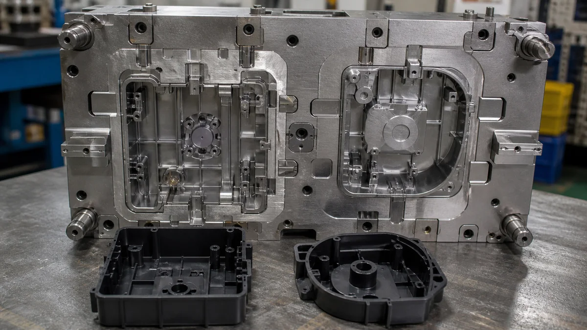
Family-mold feasibility should be evaluated feature by feature, not inferred from the fact that the parts belong to one assembly. Different cavities share one molding cycle, yet their geometries may respond differently during filling, cooling, and release.
| Geometry input | Practical consequence | Warning sign for family tooling |
|---|---|---|
| Wall sections | Affect flow and cooling response | One part is thin while another has heavy local sections |
| Flow length | Influences how resin reaches the end of each cavity | One path is short and direct while another is long or restricted |
| Part mass | Can determine which part controls cooling time | One component dominates the cooling requirement |
| Gate location | Affects resin delivery and visible gate evidence | Suitable gate positions conflict with balanced filling |
| Draft and ejection | Control reliable release from the tool | One part requires a substantially different ejection approach |
Draft is the taper that helps a molded feature release. Too little draft can increase ejection difficulty even when the cavity fills. Deep ribs, delicate clips, restrictive internal features, and cosmetic faces should therefore be identified during design for manufacturability review6.
Example: A thin cosmetic bezel and a thick mounting block may share a resin and color, but the block could govern cooling while the bezel presents a different filling or ejection risk. Their assembly relationship does not establish family-mold compatibility.
When shared processing conditions demand unacceptable compromises, compare separate single-cavity molds or multi-cavity molds dedicated to each SKU. Separate tools can isolate production quantities, revision timing, process adjustment, and inspection. They may require a greater tooling commitment, but geometry fit should be established before projected mold consolidation drives the decision.
How Should Tolerances and Cavity Inspection Be Specified?
Apply close tolerances to functional features and define inspection by cavity when cavity-to-cavity variation can affect acceptance. The drawing should identify critical datums, fits, seals, and alignment features, while the RFQ defines sample approval, measurement conditions, reporting, and the production evidence required after tooling release.
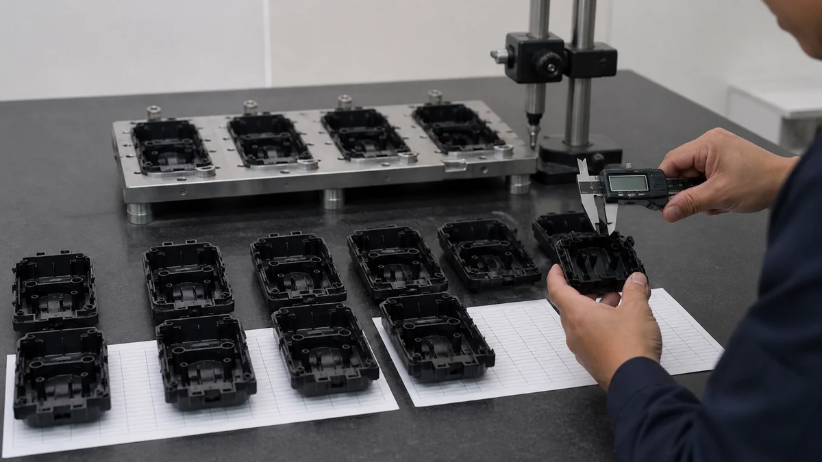
Cavity count does not establish dimensional capability. Molded dimensions can be influenced by resin behavior, wall geometry, cooling, cavity position, tool condition, and production repeatability. The drawing should separate function-controlling features from clearance and cosmetic geometry.
Prioritize characteristics such as:
- Bores or openings that locate hardware
- Mating surfaces and assembly interfaces
- Sealing lands and controlled gaps
- Alignment pins, slots, and functional hole patterns
- Clips, bosses, and fastening features
- Flatness or profile requirements that affect assembly
- Cosmetic zones with defined texture or surface-finish expectations
A datum is the reference used to locate or orient another feature. Clear functional datums matter when several molded dimensions combine in an assembly. Otherwise, individual dimensions may pass while the accumulated tolerance stack-up7 still causes poor alignment or an uneven gap.
For a multi-cavity tool, decide whether first samples and production records must identify the originating cavity. Cavity traceability8 helps distinguish a general process shift from a cavity-specific issue. In a family mold, each SKU needs its own critical-characteristic plan even though all parts share one cycle.
Define what will be measured, the measurement condition, the sampling requirement, and the result that authorizes repeat production. Specify whether approval requires first-article results, selected dimensional records, cavity-specific reporting, functional checks, or inspection of designated features. Do not assume formal reports are included.
Keep cosmetic acceptance separate from dimensional acceptance. Surface finish describes appearance or texture; dimensional tolerances control size, form, orientation, or location. A vague note such as “precision finish” does not establish an inspection method or an objective acceptance condition.
Which Mold Strategy Has the Best Total Program Economics?
The best economics come from the lowest-risk complete program, not automatically from the cheapest mold or highest cavity count. Compare tooling, cycle planning, expected demand, runners, cooling, press fit, validation, inspection, scrap exposure, revisions, inventory effects, and delivery requirements using the same part specifications.
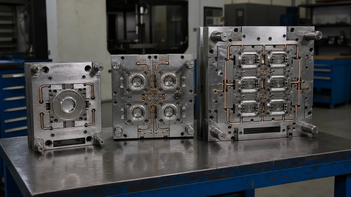
Initial tooling price and recurring part cost show only part of the economics. A single-cavity mold generally limits initial complexity but produces one part per cycle. A multi-cavity mold distributes a cycle across identical parts, although the larger tool requires broader design and validation. A family mold may replace separate tools, but balance and linked-SKU risks can offset that benefit.
| Program driver | Single-cavity | Multi-cavity | Family mold |
|---|---|---|---|
| Tooling commitment | One cavity and one part geometry | Several identical cavities | Several different part geometries |
| Output per cycle | One part | Multiple units of one SKU | Multiple related SKUs |
| Approval scope | One cavity | Dimensional and cosmetic consistency across cavities | Separate acceptance criteria for each family member |
| Inventory control | One SKU scheduled independently | Greater output of one SKU | Output ratio links SKU inventories |
| Revision exposure | Confined to one cavity | Repeated across identical cavities | One change can affect shared tooling for several SKUs |
| Main process concern | Limited output | Runner and cooling balance | Balance among dissimilar cavities |
Ask suppliers to separate tooling, sample approval, production, inspection, and secondary operations in the quotation. Mold size and shot requirements can affect press suitability. Runner and cooling design influence tool complexity, validation effort, and cycle planning.
There is no universal break-even quantity9. Annual demand, batch size, program duration, part size, resin, geometry, inspection level, expected scrap, inventory policy, and delivery pattern all affect the comparison. Each alternative must be quoted against the same material, tolerance, cosmetic, approval, packaging, and delivery requirements.
If one proposal excludes cavity-specific inspection or assumes a different demand ratio, its lower total does not represent an equivalent manufacturing plan. Compare delivered scope and program risk before comparing headline tooling or unit prices.
How Much Tooling Risk Does a Design Change Create?
Tooling risk rises as more cavities or SKUs become committed to an unsettled design. A single-cavity mold limits the immediate change exposure, while multi-cavity and family tools can require broader modification. Confirm the controlled revision, unresolved design risks, forecast confidence, and production intent before authorizing tooling.
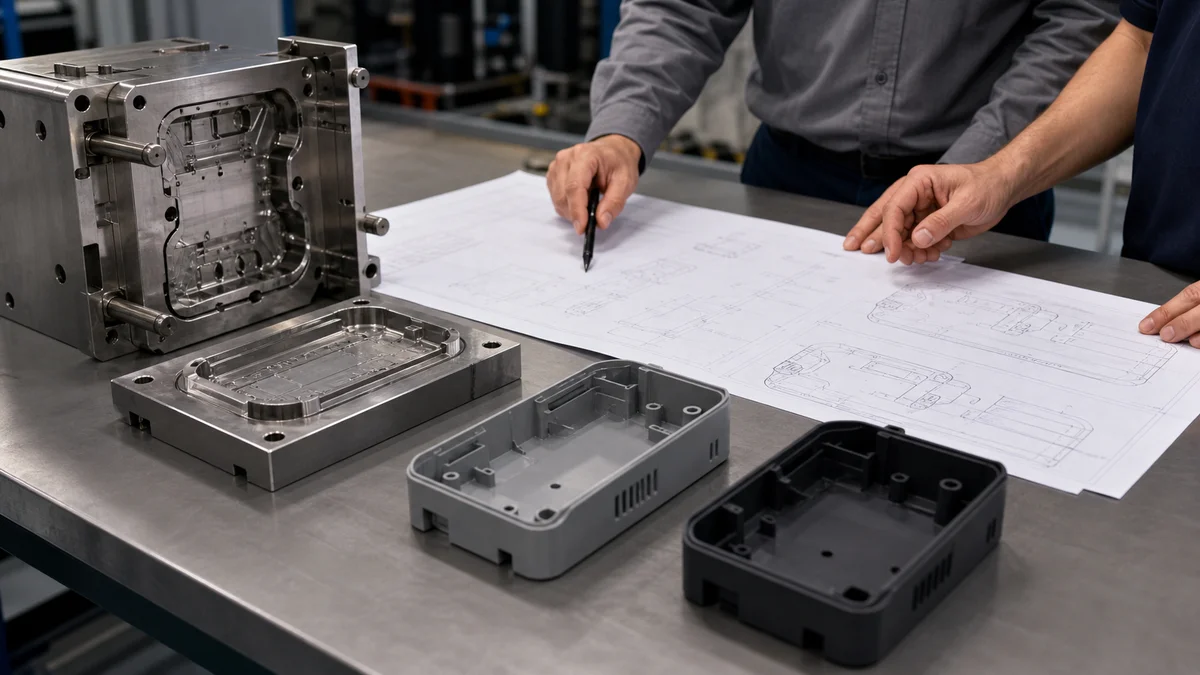
A mold converts released geometry into dedicated tooling. Programming changes alone cannot resolve every later revision, so design maturity10 should be an approval condition rather than an informal expectation.
A change to a single-cavity mold affects one cavity, although feasibility still depends on the feature and tool construction. In a multi-cavity mold, the revised feature may be repeated across several cavities. Modification can therefore extend across the tool and require renewed cavity-to-cavity approval.
A family mold links different SKUs. If one family member changes while another is stable, modification or renewed validation may interrupt production of the entire set. That coupling matters when the parts have different revision schedules or service demand.
Scenario: A family tool is proposed for a cover and base. The base is released, but the cover still has unresolved clip geometry and cosmetic-surface decisions. Combining them links the stable base to the cover’s revision exposure. Resolving the cover before release—or tooling the parts separately—may provide clearer control.
At tooling release, record the governing 3D model and 2D drawing revision, unresolved fit or appearance questions, expected changes to walls, draft, gates, bosses, clips, and interfaces, and the sample results required for release. Also state whether the parts support prototype, validation, bridge, launch, or repeat production.
A common specification mistake is presenting an evolving design as production-ready because the forecast appears attractive. High projected demand does not remove engineering uncertainty. The chosen cavity strategy should reflect both forecast confidence and the maturity of every feature being committed to the mold.
How Can Fill and Cooling Imbalance Be Addressed Before Tooling Release?
Address imbalance before tooling release by reviewing cavity geometry, runner delivery, gate locations, wall thickness, flow length, part mass, cooling demand, and ejection conditions together. Request DFM review or fill analysis when dissimilar cavities or critical features create uncertainty that cannot be resolved from nominal dimensions alone.
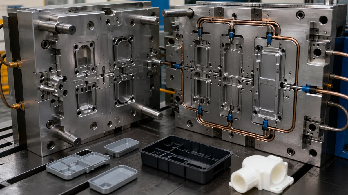
Cavity balance11 concerns whether resin can be delivered and controlled across the proposed layout without one cavity behaving as an uncontrolled exception. Cooling balance concerns whether all parts can reach an acceptable ejection condition within the shared cycle. The two issues interact, but they are not interchangeable.
Family molds are particularly sensitive because their cavities form different geometries. One part may have a longer flow path, thinner walls, greater mass, or a heavy local feature that behaves differently from its partner. Identical-part multi-cavity molds provide a more consistent starting point, yet runner paths, gate positions, cavity locations, and cooling layouts can still cause variation.
Before steel is cut, ask:
- How will the runner deliver resin to each cavity?
- Are runner paths and gate locations compatible with the parts and cosmetic zones?
- Which cavity or feature is expected to govern filling?
- Which wall section or part is expected to govern cooling?
- Are thick bosses, thin regions, long flow paths, or abrupt transitions process-sensitive?
- How will samples be marked and evaluated by cavity?
- Does the geometry justify formal fill analysis or further DFM review?
- Which geometry changes could improve balance before tooling commitment?
- How are expected scrap and sample-approval risks treated in the quotation?
Example: Placing two part shapes inside one mold base proves only that they fit the available layout. It does not prove that resin reaches both cavities appropriately or that both parts cool and eject under a stable common cycle.
Fill analysis can provide useful evidence about resin delivery, but it should support—not replace—controlled geometry, exact material data, functional requirements, cooling review, and an agreed approval plan.
What Should a Cavity-Strategy RFQ Include?
A cavity-strategy RFQ should define the controlled geometry, resin, quantities, demand pattern, production intent, critical tolerances, cosmetic requirements, inspection scope, revision status, and delivery expectations. It should also identify cavity-consistency needs, family-part relationships, design-change risks, and whether suppliers may quote alternative tooling configurations.
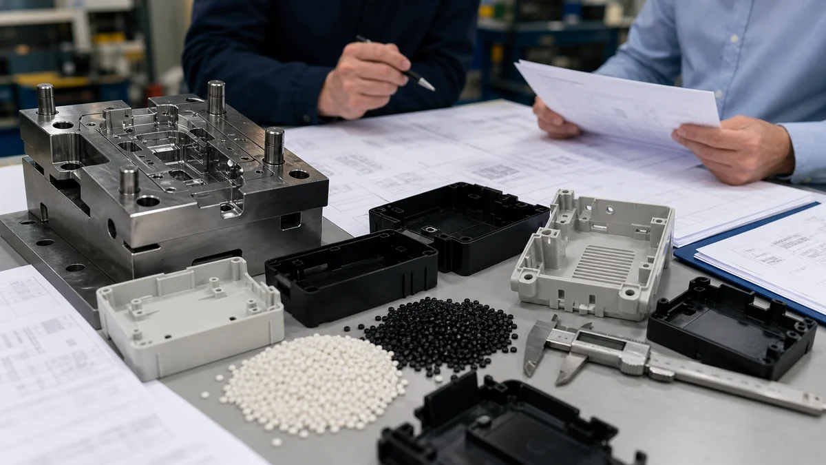
Give every supplier the same technical and commercial assumptions. Otherwise, quotations for single-cavity, multi-cavity, family, and separate-tool options may cover different tooling, validation, inspection, or production scopes while appearing directly comparable.
RFQ and tooling-approval checklist12
- 3D model: Include the complete moldable geometry, internal features, bosses, ribs, clips, draft, and assembly interfaces.
- Controlled 2D drawing: Identify the governing revision, functional datums13, critical dimensions, tolerances, cosmetic zones, and surface finish.
- Resin specification: State the exact material grade, color, additives, reinforcement, and permitted alternatives.
- Demand profile: Provide immediate quantity, batch size, annual demand, program duration, and forecast confidence.
- Production intent: Identify prototype, validation, bridge, launch, or repeat-production use.
- SKU relationship: For family tooling, list each part, its assembly relationship, demand ratio, and whether the parts must ship as a set.
- Geometry comparison: Supply wall-thickness ranges, mass differences, flow-sensitive regions, gate restrictions, draft concerns, and ejection-sensitive features.
- Cavity proposal: State a fixed cavity count only when required; otherwise, permit a supplier recommendation.
- Consistency criteria: Define the dimensions, functional results, and cosmetic characteristics requiring cavity-to-cavity control.
- Inspection and approval: State sample quantities, cavity identification, measurement conditions, inspection method, report expectations, functional checks, and release criteria.
- Revision exposure: Identify unresolved geometry, expected changes, and the documents controlling tooling release.
- Commercial scope: Define tooling ownership, packaging, delivery expectations, and whether tooling, samples, inspection, and production should be priced separately.
- Alternative configurations: Allow comparison of single-cavity, multi-cavity, family, or separate tools when the requirements permit them.
Do not ask for the “best mold type” while withholding demand ratios, resin grade, critical tolerances, or design maturity. Those inputs allow a supplier to recommend a cavity strategy instead of merely pricing the configuration named in an incomplete inquiry.
For a mold recommendation, sample plan, or quotation, send the 3D model, controlled 2D drawing, exact resin grade, quantity and annual demand, prototype or production intent, critical tolerances, surface finish and cosmetic zones, inspection expectations, revision level, SKU ratios, design maturity, and delivery requirements.
References
-
How to Determine Injection Molding Cooling Time - 85% of the cycle is spent cooling the part so that it can withstand the forces of ejection. ↩
-
Turret Punch Presses | CNC Sheet Metal Punching Machines - Turret punch presses are fundamental in sheet metal fabrication, providing high-speed, precise punching of holes, notches, and complex shapes. ↩
-
How To Select Injection Molding Material (2026) - Weilin Plastic - This guide breaks down the 7 critical material properties every injection molding engineer and quality manager must understand before approving a resin. ↩
-
The Cosmetic Process Window: Key to a No-Tweak ... - Establishing a process with the widest possible cosmetic window can help put your injection molding on cruise control. ↩
-
Filling-Balance-Oriented Parameters for Multi-Cavity Molds ... - by HH Tsai · 2022 · Cited by 19 — Using Moldex3D and the Taguchi method, this study reveals an approach to eliminate imbalanced filling of multi-cavity molds for PVC injection molding. ↩
-
Injection Molding Design Guide - Injection molding design requires careful control of wall thickness, draft angles, ribs, bosses, tolerances, and material selection to ensure manufacturability ↩
-
Datum shift + Stack-Up - The one piece of info I left off is that all GD&T is per ASME Y14.5M-1994. My datum stack used the pitch diameter tolerance from ASME B1.1 ... ↩
-
Injection Molding Quality Control: CMM Inspection, FAI ... - Traceability: Record material lot, cavity ID, machine parameters, and gauge ID for an audit-ready Quality Assurance system. ↩
-
Types of Injection Molds: Single, Multi-Cavity & Family - A single-cavity mold produces one molded part per cycle. No Universal Volume Threshold. If the higher-tooling option does not reduce recurring cost per ... ↩
-
Understanding Plastic Injection Molding Lead Times - Design for Manufacturability (DFM) analysis conducted before tooling release can save 2-3 weeks of engineering time by identifying issues when ... ↩
-
Impact of Runner Size, Gate Size, Polymer Viscosity, and ... - by M Chien · 2024 · Cited by 9 — This study examines the impact of runner size, gate size, polymer viscosity, and molding process on the filling imbalanced problem in multi-cavity injection ... ↩
-
Injection Molding RFQ Checklist for Accurate Quotes - HingTung - Learn what to include in a plastic injection molding RFQ, from CAD files and materials to tooling, quality, production volume, ... ↩
-
What Is ASME Y14.5? A Complete Guide to GD&T and ... - Define functional datums and build the Datum Reference Frame (DRF) Datums are reference surfaces, lines, or points used during inspection, ... ↩