

Parting lines, ejector marks, and gate vestiges are normal results of plastic injection molding. The specification challenge is not to demand a completely mark-free part, but to control where these witnesses may appear, what condition is acceptable, and how that condition will be inspected.
A useful drawing divides the part into functional and cosmetic surface zones. It protects sealing lands, mating faces, datums, logos, clips, and other critical features while leaving the mold designer enough freedom to develop workable parting, gating, and ejection strategies.
The goal is a specification that translates appearance preferences and functional risks into requirements the mold supplier can evaluate, quote, and verify during sample approval and production.
How Should You Classify Surfaces Before Specifying Witness Marks?
Classify every molded surface as cosmetic, assembly-facing, sealing, datum, or hidden before restricting witness marks. For each class, state whether parting lines, ejector marks, and gate vestiges are allowed, conditionally allowed, or prohibited so the toolmaker receives practical placement constraints.

Parting lines, ejector witnesses, and gate vestiges should be controlled as surface-zone requirements, not rejected as general workmanship defects. Plastic injection molding needs a mold split, a resin entry point, and a means of releasing the cooled part. The drawing must leave suitable locations for all three.
| Surface class | Acceptance risk | Specification direction | Suitable inspection basis |
|---|---|---|---|
| Primary cosmetic | Visible appearance | Identify permitted witness types and severity | Controlled visual comparison |
| Assembly-facing | Clearance or contact | Limit residual height within the assembly envelope | Dimensional or profile check |
| Sealing | Leakage or loss of compression | Prohibit disruptive flash, mismatch, and vestiges | Profile or functional check |
| Datum | Unstable location or measurement | Keep witnesses outside the datum contact area | Datum-contact verification |
| Hidden or non-critical | Low visual and functional exposure | Prefer for unavoidable witnesses | General visual acceptance |
Use the 3D model to show complete geometry and a controlled 2D drawing or surface-zone map to define acceptance. “No marks on visible surfaces” is incomplete unless those surfaces are identified. Conversely, classifying every external face as critical may leave no practical gate, split, or ejector location.
Example: A handheld enclosure can classify its front bezel as primary cosmetic, internal ribs as hidden, the perimeter tongue as sealing, and three mounting pads as datums. Ejector pins may then be proposed on supported internal ribs while the bezel, seal, and datum contact areas remain protected.
The classification should also say whether appearance or function governs. A faint line may be visually acceptable on a hidden wall yet unacceptable across a sealing land if mismatch interrupts contact. This distinction gives the supplier an actionable molded-part surface classification1 instead of an unrealistic request for a mark-free part.
Where Should the Parting Line Be Allowed or Prohibited?
Allow the parting line on low-visibility edges, ribs, transitions, or recessed areas when the pull direction and mold construction support that route. Prohibit it across logos, seals, snap interfaces, datums, and alignment features where flash or mismatch could impair appearance or function.

The parting line is the boundary where mold components meet. Its route depends on part orientation, pull direction, draft, undercuts, shutoffs, and any slides or lifters. Specify preferred and prohibited zones, but leave the toolmaker room to propose a feasible split.
During parting-line review:
- Favor a natural edge, sharp transition, rib, or recess when geometry permits.
- Keep the split away from primary cosmetic faces and molded logos unless an agreed witness is acceptable.
- Protect gasket paths, sealing lands, snap-fit contact areas, locating features, and datum surfaces.
- Determine whether flash or mismatch could obstruct assembly, alter a controlled profile, or create an objectionable handled edge.
- Confirm that the pull direction and draft support release without avoidable undercuts.
- Record the accepted route on the controlled drawing after mold DFM review.
A prohibition alone does not describe the failure condition. Mold mismatch can leave a local step; flash can project from the split. If either affects fit or sealing, define the protected area and use a measurable profile or flash limit developed with the supplier. If the concern is appearance, assign a visual inspection condition instead.
A common specification mistake is prohibiting a line across the entire exterior while also protecting every internal sealing face. That may force a stepped split, a different orientation, or added mold actions. Rank the cosmetic surfaces and preserve the sealing path as the functional priority.
The split should be settled before tooling details are fixed. Late changes can alter draft direction, shutoff geometry, undercut treatment, and ejector access. A documented mold parting-line review2 therefore protects both appearance and tool feasibility without pretending the buyer can design the complete mold from the part drawing alone.
How Should Gate Location and Vestige Form Be Specified Separately?
Specify gate placement and the remaining gate vestige as two separate requirements. Mark acceptable and prohibited gate zones first, then define whether the residual bump, depression, or trim scar may be flush, recessed, proud, or visibly trimmed on each affected surface class.

A gate is the restricted opening through which molten resin enters the cavity. Degating separates the runner or nozzle connection, but normally leaves residual geometry. An acceptable gate position does not make every resulting scar acceptable, so location and delivered condition need separate controls.
| Specification item | Drawing requirement | Practical consequence |
|---|---|---|
| Gate zone | Preferred, permitted, and prohibited regions | Preserves placement flexibility within functional limits |
| Vestige form | Flush, recessed, proud, or visibly trimmed | Defines the residual relative to the nominal surface |
| Protected feature | Seal, datum, clip, mating face, handled edge, or impact area | Prevents interference, leakage, or local weakness |
| Delivered state | As-molded, automatically separated, manually trimmed, or blended | Defines the condition presented for acceptance |
| Inspection method | Visual comparison, height measurement, or profile check | Replaces terms such as “minimal gate mark” |
Do not apply one universal gate-vestige limit3 to every resin, gate style, wall thickness, and surface. Define the functional clearance or cosmetic result, then ask the molder to propose a measurable residual compatible with the selected gate and trimming route.
Example: A molded cover has an internal battery-clearance pocket and a visible outer rim. The drawing may permit a proud, visibly trimmed vestige inside the pocket if it remains outside the battery envelope, while prohibiting gates on the rim. The supplier can then propose the gate style, vestige direction, and measurable limit for approval.
Gate restrictions should reflect local loading as well as appearance. Keep gates away from flexible clips, thin sealing edges, datum pads, and impact-sensitive corners when the residual or local processing condition could impair function. A general trimming note will not protect these features unless the prohibited gate zones and residual-form requirement are explicit.
How Should Gate Placement Balance Resin Flow, Packing, and Trimming?
Evaluate gate placement as a combined flow, packing, appearance, and trimming decision. A suitable location should support filling from thicker toward thinner regions, avoid obstructed or sensitive features, and leave enough access for consistent manual or automatic degating without damaging the finished part.

A cosmetically convenient gate can create a difficult flow path, while an effective flow location can leave an unacceptable scar. Review gate style and position with the exact resin grade, wall-thickness distribution, flow length, ribs, bosses, cavity obstructions, cosmetic zones, and production intent.
The gate generally needs to introduce resin through a substantial region so the cavity can fill and remain packable before gate freeze. The thickest wall is not automatically correct, however. It may sit beside a visible face, sealing feature, ejector restriction, or obstruction that makes trimming unreliable. The review should also consider pressure loss, hesitation, trapped air, sink, and weld-mark locations.
Should the buyer prescribe a gate style?
Prescribe one only when a functional, appearance, automation, or downstream-handling requirement demands it. Otherwise, define prohibited zones, permitted vestige form, cosmetic expectations, and production intent, then ask the supplier to propose the gate and runner arrangement.
Scenario: A rectangular electronics housing has a thicker rear connector wall, a thin front bezel, and a visible top face. A top gate may shorten the flow path but leave an exposed vestige. A rear-wall gate may protect appearance and support packing, yet the molder must determine whether resin can reach the thin bezel without hesitation, trapped gas, or an objectionable weld mark. The decision should compare complete outcomes rather than simply select the least visible point.
Manual degating may support simpler tooling, but trim access and operator variation affect the residual. Automatic degating may improve consistency for stable production, although it can require a different gate form and mold arrangement. In either case, define the delivered vestige condition rather than specifying the separation method alone. A coordinated resin flow and gate placement review4 is more useful than a cosmetic gate preference made without filling evidence.
Where Should Ejector Marks Be Allowed on a Molded Part?
Allow ejector marks on hidden, non-critical surfaces where pins or other ejector elements can push against sufficiently supported geometry. Prohibit them on primary cosmetic faces, sealing lands, functional datums, and mating interfaces, while confirming that the permitted locations still provide balanced and reliable release.
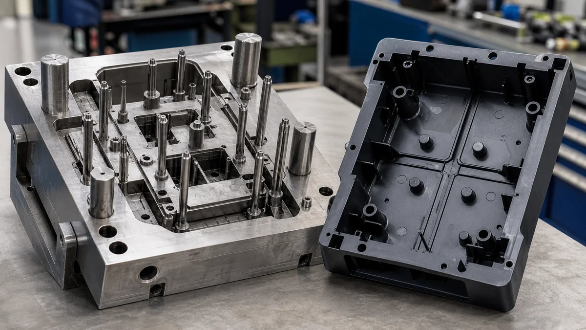
Ejector marks form where pins, sleeves, blades, or related mold elements push the cooled molding from the core. Their locations cannot be chosen by appearance alone. The system must apply sufficient, balanced force without causing sticking, whitening, cracking, distortion, or excessive local witness.
On the drawing and during DFM review:
- Mark primary cosmetic faces, sealing lands, datum contact areas, and mating interfaces as prohibited where a witness would affect acceptance.
- Prefer hidden pads, supported ribs, bosses, or non-critical internal surfaces for ejector contact.
- Avoid concentrating force on thin walls, tall ribs, unsupported spans, or impact-sensitive geometry.
- Confirm that the remaining locations distribute force across the part rather than pushing mainly from one side.
- Define whether an accepted witness may be flush, recessed, proud, discolored, or visible under the agreed inspection conditions.
Draft, draw depth, surface texture, wall thickness, resin shrinkage, cooling, and undercuts all affect the force needed for release. A deeply textured wall with inadequate draft may grip the core and increase pin loading. Moving ejectors away from every visible area without correcting release conditions can therefore worsen deformation or sticking.
Another frequent mistake is protecting entire internal pads when only small contact footprints mate with another component. That removes useful ejector locations unnecessarily. Mark the actual mating footprints and allow the surrounding supported area to be reviewed for ejection.
The toolmaker should present a complete ejector layout, not isolated pin positions. Sample approval should assess both each witness and the molded part’s free-state shape after ejection. An acceptable pin circle does not prove that the overall ejection strategy avoids distortion. This full-part ejector layout assessment5 connects cosmetic restrictions to draft, cooling, shrinkage, and structural support.
How Should Parting Lines, Ejector Marks, and Gate Vestiges Be Inspected?
Inspect each witness with a defined visual or dimensional method based on its risk. Specify the surface zone, lighting, viewing direction, viewing distance, comparison standard, measurement location, sampling frequency, and pass-or-fail criteria instead of relying on subjective terms such as minimal or smooth.
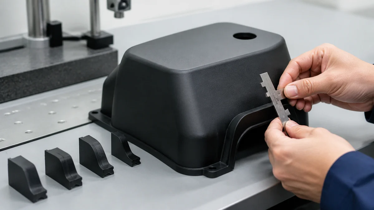
Appearance and functional geometry require different acceptance methods. A parting-line witness on a visible housing may need controlled visual review. A gate vestige near a mating feature may require a height or profile measurement. An ejector witness on a datum contact area may require verification that the usable datum remains unaffected.
For visual acceptance, specify:
- The cosmetic class or named surface being inspected.
- Lighting, viewing direction, viewing distance, and observation time.
- Whether the part is stationary, rotated, or held in assembly orientation.
- The approved color, texture, and finish condition.
- A boundary sample, reference image, or written pass-or-fail description when useful.
Dimensional acceptance should identify the characteristic, datum reference where applicable, measurement locations, allowed residual direction, and part condition. A profile measurement may be more meaningful than one height reading when flash or mismatch crosses a sealing or mating interface. Define the result that must be verified; prescribe a particular instrument only when a governing requirement makes it necessary.
State whether inspection covers initial samples, every cavity, selected production samples, or each critical area. Multi-cavity molds may require cavity identification because witness conditions can vary among cavities. The approved sample record should capture resin, color, cavity, molding state, drawing revision, and inspection conditions.
Avoid terms such as “smooth,” “minor,” or “cosmetic quality” without an acceptance basis. They allow buyer and supplier to inspect the same scar under different lighting or from different distances and reach different conclusions. A controlled visual inspection method6 keeps appearance decisions repeatable, while dimensional or profile checks protect clearance, sealing, location, and contact requirements.
How Do Witness-Mark Limits Affect Tooling Cost and Lead Time?
Restrictive witness-mark limits can change part orientation, parting-line routing, gate style, ejector layout, mold actions, degating, secondary blending, sampling, and inspection. Compare the complete tooling and production plan because a simple cosmetic prohibition can create meaningful design, validation, and handling work.
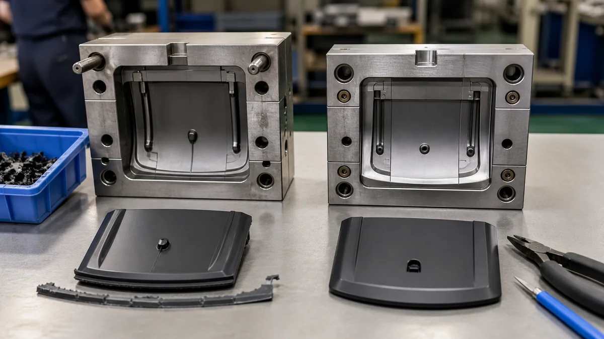
Witness restrictions affect mold architecture when they remove practical locations for the split, gate, or ejectors. The impact depends on geometry, resin, wall thickness, surface finish, quantity, cavity layout, design maturity, inspection level, and production intent. It cannot be reduced to a fixed price or schedule multiplier.
| Requirement | Potential tooling or production change | Decision to resolve before quotation |
|---|---|---|
| Broad no-parting-line zones | New orientation, stepped split, slides, or added shutoffs | Which surfaces genuinely require protection? |
| No visible gate vestige | Hidden gate, alternative gate style, automatic separation, or blending | Which residual forms actually fail acceptance? |
| Few ejector locations | Larger contact elements, added mechanisms, or greater distortion risk | Can prohibited areas be narrowed to actual contact footprints? |
| Automatic degating | More involved gate and mold arrangement | Does demand and design stability justify it? |
| Manual trimming | Recurring handling and trim variation | Is trim access practical and the residual measurable? |
| Tight cosmetic approval | More sampling, tool adjustment, and controlled inspection | Is there a zone standard or approved boundary sample? |
Manual trimming may simplify the mold arrangement but adds a repeated operation. Variation rises when the gate is difficult to reach or the required residual is close to the nominal surface. Automatic separation may reduce handling, yet the mold and gate must release consistently without tearing or marking the part.
Restrictions can also move a gate into a less favorable flow position or force ejectors onto weaker geometry. The mold may look cleaner conceptually while becoming harder to fill, pack, cool, eject, or inspect.
Ask each supplier to explain the complete tooling and degating tradeoff7, including molding, trimming, finishing, sampling, inspection, and maintenance. Quotations become comparable only when suppliers use the same resin, surface classes, vestige limits, quantity assumptions, approval method, and active revision.
What Should a Witness-Mark RFQ and Sample-Approval Package Include?
Submit a controlled model-and-drawing package that defines resin, demand, surface classes, witness permissions, residual conditions, draft, texture, critical tolerances, inspection, revision, and delivery expectations. Include sample-approval records so the quoted mold concept and accepted production appearance remain tied to the same requirements.
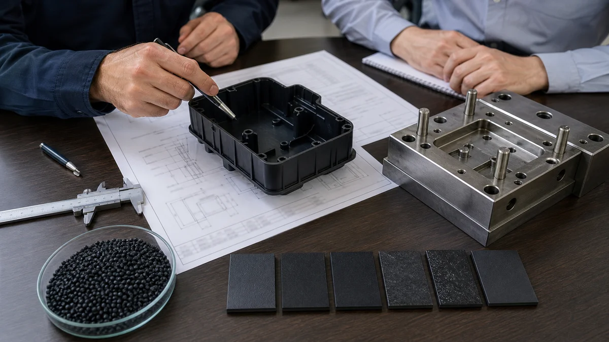
A complete package lets suppliers review parting, gating, ejection, trimming, and inspection on consistent assumptions. Send the 3D model and controlled 2D drawing together, identify the active revision, and state which document governs if they conflict.
Use this injection molding RFQ checklist8:
- ☐ Part number, drawing number, units, and active revision
- ☐ Native or neutral 3D CAD model and controlled 2D drawing
- ☐ Exact resin grade, color, additives, and approved alternatives
- ☐ Immediate quantity, annual demand, prototype or production intent, and design maturity
- ☐ Critical tolerances, functional datums, nominal wall thickness, draft, and texture
- ☐ Cosmetic, assembly-facing, sealing, datum, and hidden surface classes
- ☐ Preferred, permitted, conditional, and prohibited parting-line zones
- ☐ Permitted and prohibited gate zones plus acceptable vestige form
- ☐ Acceptable and prohibited ejector-witness zones
- ☐ Manual or automatic degating expectations and blending restrictions
- ☐ Visual inspection conditions and dimensional measurement requirements
- ☐ First-sample, cavity-specific, production-sampling, and reporting scope
- ☐ Approved boundary samples or reference images where applicable
- ☐ Finish, assembly, packaging, handling, and delivery expectations
- ☐ Required DFM outputs, mold-concept approvals, and revision-control steps
During sample approval, record the resin, color, cavity, process state, drawing revision, inspection conditions, and disposition of each witness zone. If an acceptance limit changes, update the controlled specification rather than relying on an email or an unmarked sample.
Name the manufacturing process correctly. Plastic injection molding fills a mold with molten polymer and ejects the cooled part. CNC machining removes material from solid stock. CNC turret punching uses programmed punch tools on sheet. Metal stamping cuts or forms sheet with dedicated dies. Sheet metal fabrication may combine cutting, punching, bending, welding, and finishing. These processes are distinct, and “CNC turret punching, CNC punch press, CNC-controlled stamping equipment, or metal stamping depending on the actual process” is not one standard process term. A process-correct mold RFQ prevents suppliers from quoting incompatible manufacturing assumptions.
For a mold recommendation, sample plan, or quotation, send the 3D model, controlled 2D drawing, exact resin grade, quantity, prototype or production intent, critical tolerances, surface finish and texture, witness-zone restrictions, inspection expectations, revision level, and delivery requirements.
References
-
Cosmetic Specifications of Injection Molded Parts - These specifications, separated into four grades, provide quantitative definitions and recommended methods of inspection and measurement to determine an ... ↩
-
Draft Angle Guidelines for Injection Molding - Draft is a slight taper on faces parallel to the mold's opening direction. It reduces scraping and sticking during ejection, preventing cosmetic defects, ... ↩
-
Gate Vestige in Injection Molding: Why It Happens and How to ... - Gate vestige is the visible or physical remnant left on a molded part after the gate separates from the part. ↩
-
A Strategic Approach to Gate Location in Injection Molding - a common best practice is to gate into the thickest cross-section of the part. This allows the material to flow from thick to thin sections, ↩
-
Injection Molding Guide: Process, Design Tips & Materials - A common starting point is 1 to 2 degrees, with more draft for textured surfaces. Ejector pins can leave marks, while undercuts may require side-actions, ... ↩
-
How Should Buyers Define Cosmetic Surface Standards for ... - A useful visual standard defines lighting, viewing distance, angle and inspection time. For example, a project may specify 500-1,000 lux, 0.5-1.0 m viewing ... ↩
-
Basics of Injection Molding Design - Be sure to allow for easy manual or automatic degating. Gate should minimize flow path length to avoid cosmetic flow marks. In some cases, it may be necessary ... ↩
-
Injection Molding Checklists by Project Stage: RFQ, DFM, ... - Examples of RFQ inputs, DFM review notes, trial records, and acceptance documents used to confirm technical alignment before tooling approval and production ... ↩