

Aluminum 6061 is often considered for CNC machined brackets, housings, shafts, fixtures, frames, and prototypes because it balances several useful characteristics. That does not make it the correct alloy for every aluminum component. Selection should begin with loading, environment, geometry, joining method, surface finish, tolerances, and production intent.
Temper matters as much as the alloy designation. A drawing that says only “aluminum” leaves sourcing and machining assumptions unresolved. Specifying 6061-T6 gives the supplier a clearer basis for reviewing stock, tooling, process sequence, finishing, and inspection.
The decisions below explain when 6061 is a sensible starting point, when another material or process deserves review, and what evidence a supplier needs to prepare a useful quotation.
When Does Aluminum 6061 Provide the Right Balance of Properties?
Choose aluminum 6061 when the part needs balanced machinability, moderate strength, low weight, corrosion resistance, weldability, and finishing flexibility. Review another alloy or process when exceptional strength, severe fatigue, extreme exposure, or extensive sheet forming is the dominant requirement.
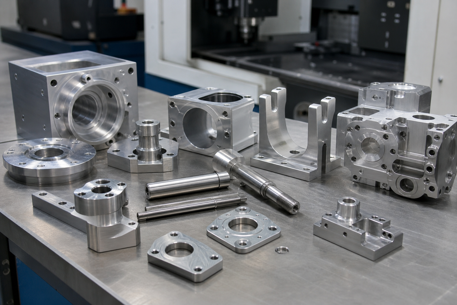
6061 is useful because it addresses several ordinary mechanical requirements without being selected for one exceptional property. Typical candidates include machined brackets, housings, fixtures, frames, and mechanical prototypes. The final choice still needs to reflect the actual load path, service environment, joining sequence, geometry, and acceptance criteria.
The 6061 material selection1 should connect every desired property to a defined requirement:
| Specification question | When 6061 may fit | When further material review is needed |
|---|---|---|
| How will the part be made? | Milling or turning from solid stock dominates | Deep forming, casting, or another route dominates |
| What mechanical duty applies? | Loads are moderate and understood | Exceptional strength or severe fatigue controls the design |
| What exposure is expected? | General corrosion resistance is sufficient | Aggressive or poorly defined exposure controls acceptance |
| Will the part be joined? | Welding or mechanical assembly is planned | Joining conflicts with the specified alloy or temper |
| Is secondary finishing required? | Anodizing, painting, or another compatible finish is planned | A specialized surface response is essential |
Avoid approving a material from vague labels such as “strong,” “lightweight,” or “weatherproof.” Those words do not define loading direction, stress concentration, service temperature, exposure duration, or the surfaces that must remain functional after finishing.
Example: A rigid equipment bracket with machined mounting faces, threaded holes, moderate service loads, and a localized cosmetic finish may justify reviewing 6061-T6 first. A fatigue-critical component under severe cyclic loading needs a more specific engineering assessment. The general-purpose reputation of 6061 is not sufficient evidence for approval.
Which CNC Machined Geometries Are a Good Fit for 6061?
6061 is a strong candidate for parts milled or turned from plate, bar, or other solid stock, including housings, shafts, fixtures, pockets, slots, and bores. Geometry still needs review because thin walls, deep features, small corners, and multiple machining orientations can dominate difficulty.

Begin with the dominant shape. Prismatic parts such as blocks, plates, housings, pockets, and mounting fixtures generally point toward CNC milling. Rotational parts such as shafts, bushings, flanges, and disks generally point toward CNC turning. A mostly round component with cross-holes, flats, or off-axis pockets may need separate milling or a turn-mill route.
A useful CNC machining geometry review2 should identify:
- Deep pockets and narrow cavities, where long tool reach can increase deflection, vibration, and chip-evacuation difficulty.
- Thin walls and broad plates, which may move under cutting or clamping forces.
- Small internal corner radii, because a rotating cutter cannot produce a perfectly sharp internal corner.
- Long unsupported sections that may be sensitive to chatter or workholding pressure.
- Features on several sides that require repositioning, indexing, or additional alignment checks.
- Tight face-to-bore and cross-side relationships that span different setups.
Features produced in one setup are generally easier to control relative to one another than features created after reclamping. Where several setups are unavoidable, the drawing should use functional datums and state whether position, perpendicularity, coaxiality, or another relationship controls assembly. This prevents tolerance stack-up from being hidden inside unrelated linear dimensions.
Scenario: Consider a 6061 housing with a deep central pocket, thin perimeter walls, and mounting holes on three sides. The alloy may cut cleanly, yet pocket depth, wall movement, tool access, clamping strategy, and cross-setup hole position will shape the quote. Mark the functional walls, bores, and hole relationships so the supplier does not treat every surface as equally critical.
If extensive bending or deep forming dominates, review a sheet metal material and fabrication route instead of defaulting to a stock-machined part.
Should You Choose 6061 When the Machined Part Will Be Welded?
6061 should be considered when a CNC machined component will later be welded or incorporated into a fabricated assembly. The RFQ must identify the complete joining and thermal sequence because welding can affect temper assumptions, distortion, dimensional acceptance, surface treatment, and inspection planning.

The decision is not simply whether 6061 can be welded. The supplier needs to know what happens before and after welding, which features establish the final assembly, and when dimensions will be accepted. Machining a feature first may improve access, but subsequent heat input and restraint can alter its position relative to other surfaces.
Which operations must be disclosed?
State whether the component will be welded, locally formed, thermally processed, straightened, anodized, painted, masked, pressure tested, or assembled. Identify who performs each operation and whether inspection applies to the separate component, the welded fabrication, or both. This allows the welding and machining sequence3 to be reviewed with stock allowance, workholding, datums, finishing, and dimensional acceptance.
A locating bore illustrates the sequence problem. If it is finished before the block is welded into a frame, welding distortion may change the bore’s position relative to the completed assembly. Machining the bore after welding may provide a clearer route when final alignment is critical. The drawing should define the assembly datums and the stage at which bore size and position are verified rather than leaving the supplier to infer them.
Do not assume that material supplied as 6061-T6 retains an identical condition after welding or other thermal operations. If the finished assembly depends on a particular condition, address that requirement for the completed manufacturing route. The starting temper alone does not explain the final state.
6061 may deserve preference over a less welding-friendly high-strength alloy when joining is essential. That comparison does not replace load analysis. Strength, fatigue, exposure, distortion, finish, and inspection requirements still need independent confirmation.
How Should Tolerances, Finishing, and Inspection Be Specified for 6061?
Specify 6061 tolerances by feature function, apply surface-finish requirements only where needed, and define whether dimensions apply before or after finishing. Pair every critical requirement with an appropriate inspection expectation instead of assuming the alloy designation establishes machining or measurement capability.
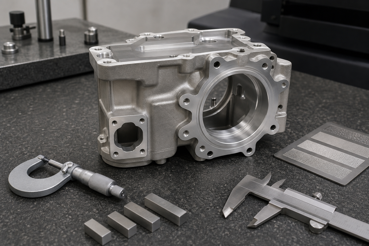
Use a tiered tolerance plan instead of applying one tight limit across the part. Bearing bores, sealing faces, dowel holes, press-fit areas, mating surfaces, and alignment features may need closer control than clearance pockets, cosmetic edges, lightening cuts, or non-contact surfaces.
For many non-critical aluminum features, ±0.10 mm to ±0.13 mm can serve as a practical quoting baseline when tighter control is unnecessary. This is supplier- and geometry-dependent, not a universal capability. A feature below about ±0.05 mm becomes a machining and inspection decision that may affect fixturing, tool-wear control, temperature management, process sequence, and measurement method.
| Feature type | Drawing control | Practical inspection question |
|---|---|---|
| Ordinary non-critical dimension | General tolerance note or applicable standard | Is routine dimensional verification sufficient? |
| Functional bore or mating size | Explicit feature tolerance | Which method can verify the stated size on this geometry? |
| Hole pattern or face relationship | Datums and focused GD&T | How will position, flatness, or orientation be established? |
| Finish-critical surface | Local Ra or defined cosmetic requirement | Is recorded roughness measurement or visual approval required? |
| Coated functional interface | Masking and acceptance-stage note | Does final acceptance apply before or after finish buildup? |
Use GD&T for functional relationships4 when position, flatness, perpendicularity, parallelism, coaxiality, or profile expresses assembly intent better than tighter size limits. Clear datums also reduce ambiguity from chained dimensions and tolerance stack-up.
Avoid a blanket fine-finish note. It can expand finishing passes and inspection without improving function. Mark sealing, sliding, bearing, mating, and visible cosmetic surfaces locally. For anodizing, painting, blasting, sanding, or chemical polishing, identify treated and masked areas, then state whether tolerance acceptance occurs before or after finishing.
When Can 6061 Help Control Machining Cost and Lead Time?
6061 can support cost and schedule control when suitable stock is readily available and the geometry permits efficient conventional machining. It does not guarantee a lower quotation or faster delivery because stock size, setups, material removal, finishing, inspection, quantity, and schedule still determine the manufacturing plan.

Treat availability and machinability as useful quote signals, not promised commercial outcomes. A supplier may commonly source 6061 plate or bar, but the exact temper, dimensions, quantity, material documentation, and destination can change purchasing assumptions. Request the specified material rather than assuming that the required stock is available locally.
Several factors can outweigh the alloy’s general machining advantages:
- Stock envelope: A component that barely exceeds an available plate or bar size may need a different starting blank and more material removal.
- Removed volume: A deep-pocketed housing can require substantial roughing even when the alloy cuts cleanly.
- Setup count: Multi-face features may require reclamping, dedicated workholding, and checks between orientations.
- Production intent: A prototype, pilot lot, and repeat production order can justify different fixturing, batching, and inspection plans.
- Secondary finishing: Anodizing, painting, blasting, polishing, masking, and cosmetic handling add separate process steps.
- Inspection scope: First article reports, full dimensional reports, sampling, or selected 100 percent inspection require different effort.
- Delivery conditions: Partial shipments, staged approvals, and requested delivery dates should be stated explicitly.
The CNC machining cost drivers5 should therefore be reviewed at feature level. A simple plate with accessible holes and ordinary tolerances is fundamentally different from a thin-walled housing made from the same 6061-T6 stock. Deep pockets, several machining orientations, local fine finishes, and documented positional inspection can dominate the second part’s plan.
Standardizing 6061 across repeat part families may simplify material purchasing and process planning when the same grade and temper genuinely satisfy each design. It should not override exceptional loading, corrosive exposure, welding sequence, stock-size constraints, or geometry that requires a different manufacturing route.
Why Must the RFQ Specify the Exact 6061 Temper?
The RFQ must state the exact 6061 temper because material condition affects sourcing assumptions, machining behavior, finishing, and compatibility with later forming or thermal operations. Specifying only “aluminum” or even “6061” leaves the supplier without a controlled basis for planning or acceptance.

The alloy designation and temper communicate different information. “6061” identifies the alloy family, while a designation such as T6 identifies a material condition. Omitting the condition can create disagreement about the stock being quoted, expected machining behavior, finishing response, and compatibility with later welding, forming, or thermal processing.
Softer or gummier conditions may require a different approach to tooling and chip evacuation. Built-up edge in aluminum machining6 occurs when material adheres near the cutting edge, changing cutting behavior and potentially degrading the generated surface. Chips that are not cleared effectively may be recut, which can affect finish and process stability.
The buyer should normally avoid prescribing feeds, speeds, tool geometry, coolant delivery, or air-blast settings. Those choices belong in the supplier’s process plan. The controlled specification should instead define material condition, geometry, critical tolerances, surface requirements, secondary operations, and acceptance evidence.
A frequent specification failure is sending a model marked only “aluminum, clear anodize” while an email or purchase request informally mentions 6061-T6. That leaves several questions open: Which document controls? Is T6 mandatory? Which surfaces are anodized or masked? Do critical dimensions apply before or after finish buildup? Resolve these points on the controlled drawing and identify the active revision.
If forming or thermal processing requires a different temper, do not transfer machining assumptions from 6061-T6 without review. State the operation sequence and required final condition. When material documentation, traceability, a preferred source, or buyer-supplied stock matters, include that requirement before quotation rather than treating it as a later purchasing note.
Is the Part Actually Intended for CNC Machining?
Confirm CNC machining when the part must be produced by removing material from solid 6061 stock. Do not use machining, turret punching, stamping, sheet metal fabrication, and plastic injection molding interchangeably; each process has different materials, geometry rules, tooling, tolerances, and RFQ requirements.
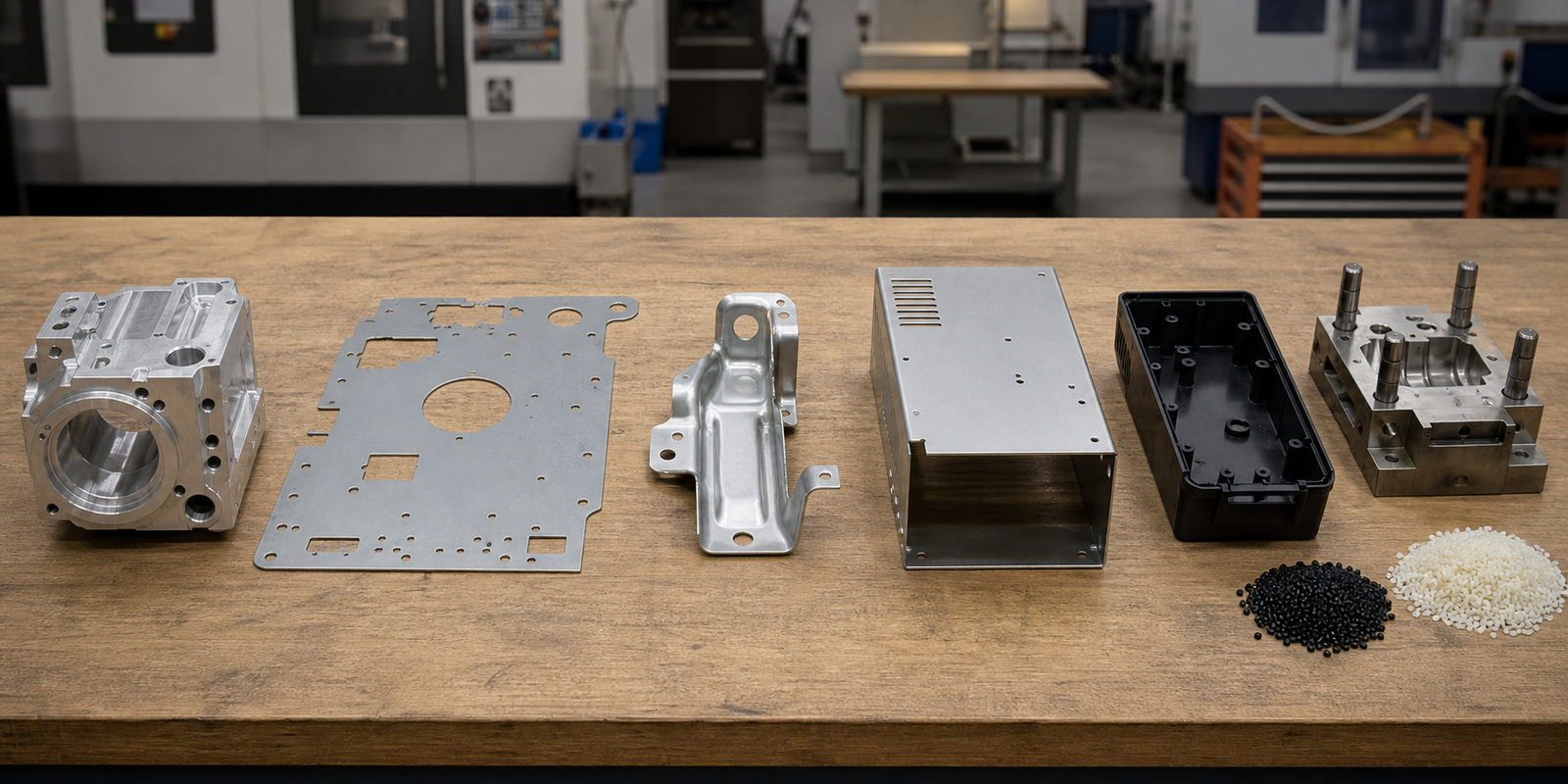
Identify the process before requesting a material quotation. A solid 6061 housing with milled pockets is not specified like a punched sheet bracket, a die-stamped component, or a molded plastic housing.
| Process | How the shape is created | Specification details that drive the quote |
|---|---|---|
| CNC machining | Milling, turning, drilling, boring, or reaming removes material from solid stock | Stock form, cutter access, setups, datums, tolerances, and machined finish |
| CNC turret punching or CNC punch press work | Programmed punch tools cut or form sheet | Sheet grade and thickness, feature geometry, burr direction, and downstream bends |
| Metal stamping | Dedicated dies cut or form sheet material | Material condition, die strategy, forming direction, springback, burr control, and production volume |
| Sheet metal fabrication | Cutting, punching, bending, welding, and finishing may be combined | Flat pattern, bend radii, joining, finish, and assembly sequence |
| Plastic injection molding | Polymer is formed inside a mold | Resin, wall thickness, draft, gate location, ejection, tooling, and production intent |
The phrase CNC turret punching, CNC punch press, CNC-controlled stamping equipment, or metal stamping depending on the actual process terminology7 is inherently ambiguous because “CNC turret punching, CNC punch press, CNC-controlled stamping equipment, or metal stamping depending on the actual process” is not one standard process term. It may refer informally to CNC turret punching, a CNC punch press, CNC-controlled stamping equipment, or general metal stamping. Replace it with the intended operation before quotation.
Example: A thin enclosure panel with punched ventilation slots and several bends is primarily a sheet metal fabrication part, even when CNC-controlled equipment performs the punching. Its drawing should address sheet thickness, bend geometry, springback, and burr direction. A thick 6061 enclosure milled from plate with pockets, threads, and precision mating faces is a CNC machined part. Tool access, datums, setup relationships, and machined finish control that quotation.
If the route remains open, define functional requirements and request manufacturing alternatives instead of assigning an inaccurate process name.
What Information Should a 6061 CNC Machining RFQ Include?
A complete 6061 CNC machining RFQ should define the controlled geometry, exact material and temper, quantity, production intent, critical features, finish, secondary operations, inspection evidence, revision, loading, exposure, and delivery expectations. These inputs allow the supplier to confirm material fit and quote manufacturing risk.
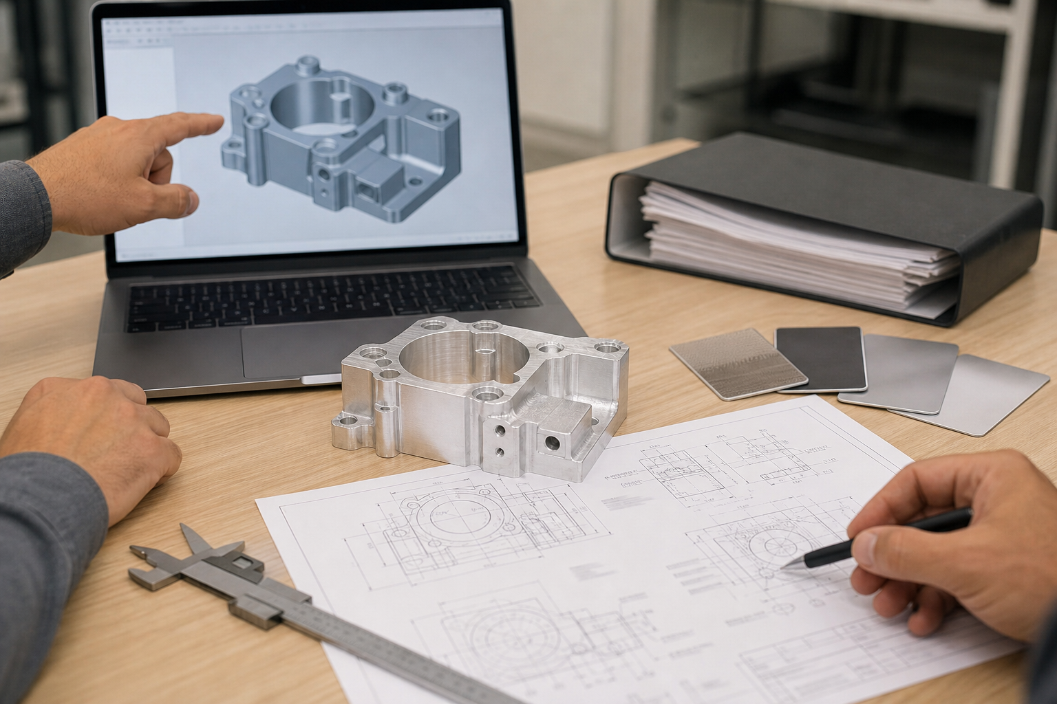
Send both a 3D CAD model and a controlled 2D drawing. The model communicates full geometry and supports manufacturability review. The drawing controls specifications that may not be reliable from the model alone, including tolerances, GD&T, datums, threads, surface finish, units, notes, inspection requirements, and revision. If the files disagree, identify which document governs before quotation.
Use this 6061 CNC machining RFQ checklist8 before release:
- ☐ 3D model in a usable format
- ☐ Controlled 2D drawing with part number, units, and active revision
- ☐ Exact aluminum grade and temper, such as 6061-T6 when required
- ☐ Material source, buyer-supplied stock, documentation, or traceability requirements where applicable
- ☐ Immediate quantity and prototype, validation, pilot, or production intent
- ☐ Estimated annual usage or repeat-order expectation when known
- ☐ Functional, assembly-related, cosmetic, and non-critical features identified
- ☐ General tolerances plus explicit critical tolerances
- ☐ GD&T controls with clear datums where feature relationships matter
- ☐ Surface-finish requirements assigned to specific surfaces
- ☐ Anodizing, painting, blasting, polishing, masking, deburring, edge, or marking requirements
- ☐ Statement of whether dimensions apply before or after finishing
- ☐ Welding, forming, thermal processing, assembly, or testing operations
- ☐ Inspection method, sampling level, reports, and delivery evidence required
- ☐ Relevant loading, fatigue, temperature, corrosion, or exposure concerns
- ☐ Required delivery date, partial-shipment expectations, and approval stages
Replace phrases such as “high precision,” “weatherproof,” and “best finish” with functional conditions and measurable acceptance requirements. Identify the features that control fit, sealing, alignment, motion, or appearance. This evidence allows the supplier to assess whether 6061 fits and whether geometry, tolerance, finishing, inspection, or secondary operations require clarification before a quotation is prepared.
For a material recommendation or quotation, send the 3D model, controlled 2D drawing, exact material grade and temper, quantity, prototype or production intent, critical tolerances, surface finish, inspection expectations, active revision, secondary operations, exposure conditions, and delivery requirements.
References
-
Aluminum 6061-T6 - ASM Material Data Sheet - Combines relatively high strength, good workability, and high resistance to corrosion; widely available. Mechanical Properties Hardness, Machinability 50 % 50 % ↩
-
How Should Engineers Redesign Deep Pockets, Thin Walls, and ... - Discover how CNC design flaws like thin walls and undercuts raise cost and how early DFM improves machining efficiency and stability. ↩
-
6061 Aluminum Alloy: Properties, Applications, and Machining Guide - ... welding or a symmetrical sequence to minimize residual stress and distortion. Welding Technique: Apply low-current, fast-travel welding to ... ↩
-
Relating the Secondary Datum Feature to Primary Datums - The ASME Y14.5 2009 Standard tells us, “A datum feature is selected on the basis of its functional relationship to the tolerance feature and the ... ↩
-
CNC Machining Cost Reduction Guide: How to Reduce CNC ... - Learn CNC machining cost reduction strategies for your parts. Discover how CNC machines, smart design, and material choices can reduce machining cost, ... ↩
-
Surface finish in high-speed CNC machining of aluminum - PatSnap - Thermal management at the cutting zone directly governs built-up edge formation, chip evacuation, and surface texture — and the evidence ... ↩
-
Metal Punching & Stamping: What You Need to Know - HRCCNC - Metal punching focuses on creating holes in sheet metal by removing material. Metal stamping, on the other hand, shapes metal into new forms using forming dies. ↩
-
CNC Machining RFQ Template Guide - uneed - A drawing confirms dimensional limits, tolerance zones, geometric dimensioning and tolerancing (GD&T) — according to ASME standards for geometric dimensioning ... ↩