

Choosing between aluminum 6061 and 7075 is not simply a question of which alloy is stronger. The right choice depends on what the CNC machined part must withstand, how it will be joined and finished, which dimensions control function, and how material identity and final conformance will be verified.
6061 is often the balanced option for general mechanical parts. 7075 becomes relevant when strength-to-weight performance or resistance to permanent deformation governs the design. Neither alloy is automatically superior for every bracket, housing, fixture, or structural component.
Start with the governing requirement, then connect alloy, temper, stock form, geometry, joining, finishing, tolerance, and inspection in one manufacturing specification.
Which Part Requirement Should Govern the Choice Between 6061 and 7075?
Choose the alloy from the requirement that controls part acceptance: load, fatigue exposure, resistance to permanent deformation, corrosion environment, joining method, or verification plan. Use 6061 for balanced requirements and consider 7075 only when its strength-to-weight potential addresses a documented design need.
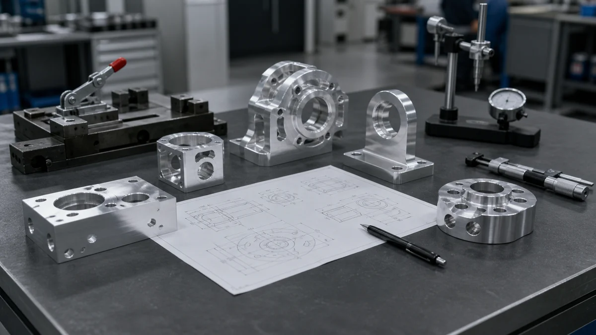
Treat 6061 and 7075 as different engineering options, not as lower and higher quality grades. First identify the failure mode the material choice must prevent. That might be excessive deflection, permanent deformation, fatigue damage, corrosion, an incompatible joining route, or inability to verify a critical feature.
Use a selection matrix to keep the decision tied to evidence:
| Governing requirement | Initial alloy direction | Evidence needed before release |
|---|---|---|
| Balanced mechanical and manufacturing needs | Start with 6061 | Loads, environment, geometry, joining, and finish |
| Strength-to-weight controls the design1 | Evaluate 7075 | Calculations, deformation limits, or supported validation requirements |
| Conventional fusion welding is mandatory | Give 6061 priority | Joint design, weld sequence, and final acceptance condition |
| Corrosion exposure is significant | Compare the complete alloy-and-finish system | Exposure description, protected surfaces, and inspection criteria |
| Tight interfaces control assembly | Do not select by alloy name alone | Datums, tolerances, stock form, fixturing risk, and inspection method |
The load case should define force direction, support conditions, peak loading, repeated loading, and the consequence of permanent set. Fatigue exposure should distinguish occasional loading from sustained cycling. Environmental information should identify moisture, chemicals, outdoor service, or contact with dissimilar materials where relevant.
A common specification mistake is writing “7075 for extra quality” without identifying a functional requirement. That gives engineering, purchasing, and manufacturing no objective basis for approving the added material and process implications. If both alloys satisfy the design, request alternatives and compare the complete machining, finishing, inspection, and supply plans rather than headline strength or raw stock cost.
When Is 6061 the Better Choice for a CNC Machined Part?
Choose 6061 when the part needs a balanced combination of machinability, corrosion resistance, stock availability, weldability, finishing compatibility, and cost rather than exceptional strength-to-weight performance. It is a practical starting point for many brackets, housings, fixtures, and general mechanical components.
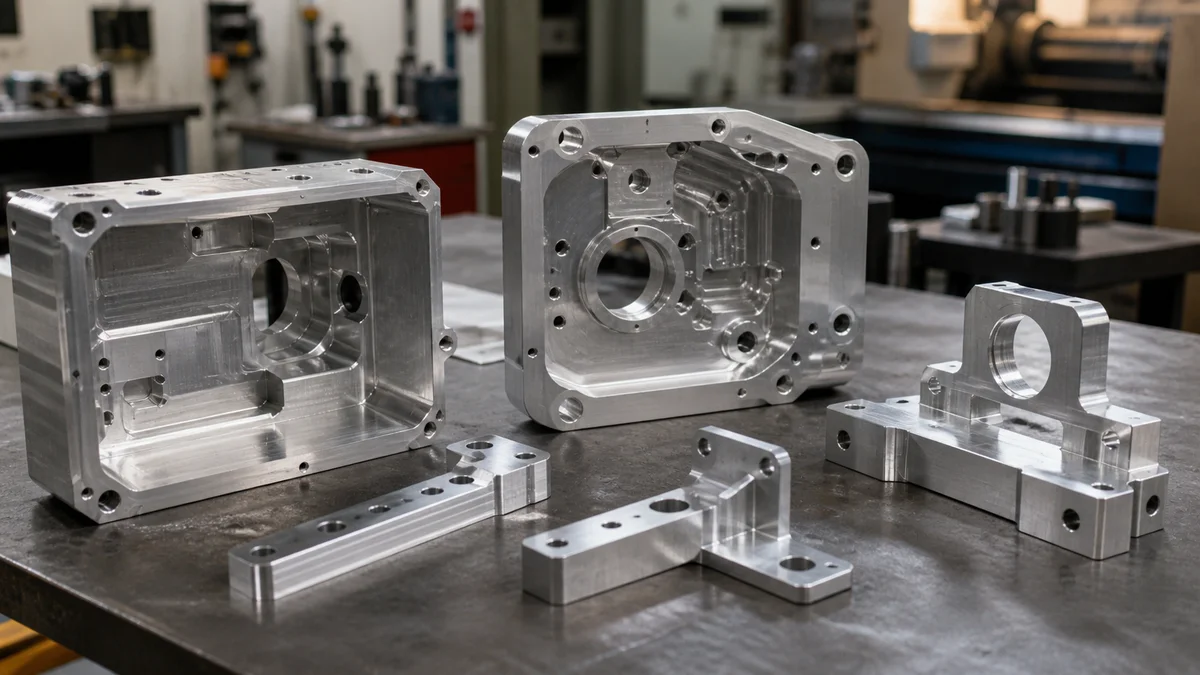
6061 is often appropriate when several moderate requirements matter at once. A housing may need accessible pockets, stable mounting faces, an anodized exterior, and practical corrosion resistance. A fixture may need threaded holes, repeatable datums, and straightforward stock replacement. In these parts, balanced manufacturing performance2 may be more useful than maximizing one mechanical property.
Use 6061 as the starting candidate when the part:
- Does not depend on the higher strength-to-weight potential of 7075.
- Will be milled or turned from plate, bar, or another solid stock form.
- May be welded or incorporated into a fabricated assembly.
- Needs anodizing, painting, blasting, or another defined secondary finish.
- Is a prototype or repeat component for which sourcing and machining efficiency matter.
- Faces an environment that can be addressed by the selected alloy-and-finish system.
Application names are filters, not proof. A bracket can be lightly loaded or structurally critical. A housing can be a protective cover or part of a load path. The specification still needs the operating load, environmental exposure, mating interfaces, wall thickness, surface treatment, and critical tolerances.
Does easier machining remove geometry risk?
No. Deep pockets, thin walls, long unsupported features, small internal radii, and details spread across several faces can create tool access, deflection, chip evacuation, and setup problems in either alloy. Machinability does not compensate for weak workholding geometry or an impractical cutter approach.
Cost also remains conditional. 6061 may simplify procurement or machining, but the finished quotation still depends on stock size, removed material, setup count, quantity, surface finish, secondary operations, inspection scope, and delivery expectations. Specify the exact temper and product form rather than assuming suitable stock is locally available.
When Does a Strength-Driven Design Justify 7075?
Consider 7075 when strength-to-weight performance or resistance to permanent deformation is a primary, documented design constraint. Confirm the load case, fatigue exposure, corrosion environment, joining method, finishing route, and inspection plan before specifying it, because higher strength alone does not make it universally preferable.
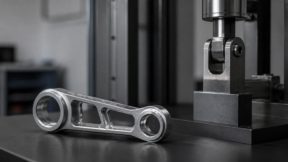
A defensible 7075 specification connects the material to a measurable design problem. The component may have a restricted envelope, a mass limit, or a load case that leaves insufficient margin with 6061. Record that reason through calculations, acceptance criteria, or a supported validation plan.
Do not stop at static strength. Repeated loading, stress concentrations, section transitions, fastener interfaces, surface condition, and the operating environment can all affect the decision. Geometry matters as well: thin walls, abrupt changes in section, deep material removal, or asymmetric features may introduce machining and dimensional risks that the alloy designation cannot resolve.
Scenario: A compact mounting link has a fixed external envelope and cannot be made thicker because adjacent components occupy the available space. Analysis indicates that a 6061 version does not meet the specified resistance to permanent deformation, while a 7075 design may satisfy the stated mass and load constraints. This is a valid reason to evaluate 7075, but it is a teaching scenario rather than a verified production case.
Before approving 7075, ask:
- Which load, mass, or deformation limit requires it?
- Is the loading static, cyclic, impact-related, or combined?
- Is conventional fusion welding part of the assembly route?
- Does the service environment require a defined protective finish?
- Will finish buildup affect fitted diameters or other critical dimensions?
- Can the required temper and stock form support the geometry and quantity?
- Which material records and dimensional results are required at delivery?
A common mistake is substituting 7075 into an existing 6061 drawing without reviewing joining, finishing, stock form, or process sequence. Material substitution should be a controlled engineering change with explicit approval criteria, not an informal purchasing upgrade.
Which Temper and Stock Form Should the Drawing Specify?
Specify the complete alloy, temper, and product form because “6061” or “7075” alone does not fully define the machining stock. Plate, bar, and extrusion can differ in availability, residual stress, geometry, and material-removal strategy, especially for thin, broad, asymmetric, or heavily pocketed parts.
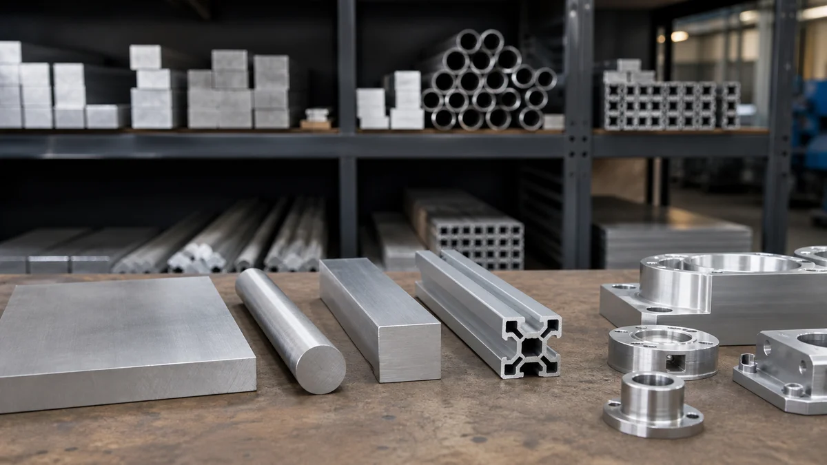
The material callout should tell purchasing and manufacturing what must be supplied. At minimum, state the alloy and temper or condition. If product form affects function, stability, traceability, or machining strategy, identify plate, bar, extrusion, or another approved form as well.
| Product form | Geometry it may suit | Machining risk to review | Drawing or RFQ requirement |
|---|---|---|---|
| Plate | Broad prismatic parts and housings | Movement after unbalanced face or pocket removal | Required thickness, critical faces, and orientation constraints |
| Bar | Smaller prismatic or rotational parts | Stock allowance and concentric material removal | Section or diameter and whether oversize stock is acceptable |
| Extrusion | Parts compatible with an existing profile | Profile variation, datum selection, and local cleanup | Profile, temper, machining datums, and allowable variation |
| Approved alternative | Programs needing sourcing flexibility | Changed properties, stability, or finishing response | Approval authority and characteristics that must remain equivalent |
Residual stress deserves attention when machining removes a large proportion of the starting material or leaves uneven sections. A broad plate with one deep pocket may move during roughing. Thin walls and asymmetric features can also respond to clamping and cutting forces. Either alloy may require a planned roughing sequence, balanced material removal3, stable workholding, and material left for final passes.
Should the drawing permit equivalent materials?
Only when engineering defines equivalence. Approval may depend on mechanical properties, temper, product form, corrosion behavior, finishing response, dimensional stability, or material documentation. A note such as “6061 or equivalent” transfers an unresolved design decision to purchasing or the supplier without supplying acceptance criteria.
Another mistake is using convenient prototype stock and silently assuming the production route will be identical. State prototype or production intent, immediate quantity, projected repeat demand, revision stability, and approved alternatives before quotation. That lets the supplier evaluate stock commitment and machining strategy without guessing.
Does Fusion Welding Rule Out 7075 for the Assembly?
If conventional fusion welding is a decisive assembly requirement, 6061 is generally the more practical choice, while 7075 is generally not selected for that route. Declare welding before quotation because it affects alloy selection, temper, machining sequence, distortion control, finishing, and final dimensional acceptance.
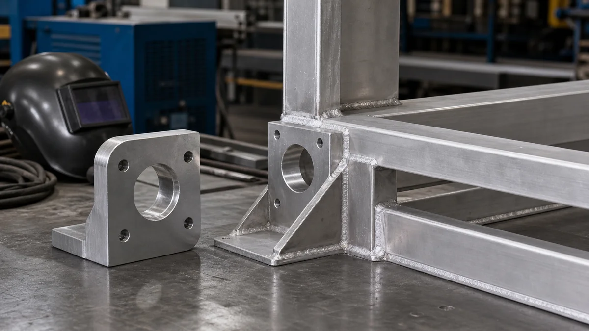
Welding belongs in the material-selection decision; it should not appear as an unreviewed secondary operation after the machining plan is complete. The RFQ should identify the joining process, joint location, assembly sequence, access requirements, and whether critical dimensions apply before or after welding.
A welded assembly review should establish:
- Whether fusion welding is mandatory or an approved mechanical joining method is possible.
- Which machined datums, bores, faces, or hole patterns could move during joining.
- Whether critical features require finish machining after welding.
- Which temper or final material condition governs acceptance.
- Whether anodizing, painting, masking, or another finish occurs before or after assembly.
- What inspection applies to the completed assembly rather than only the separate machined component.
Scenario: A machined mounting block will be welded to an aluminum frame, and its bore must align with a second bearing location after assembly. Selecting 7075 only because the block appears highly loaded conflicts with the planned conventional fusion-welding route4. A coherent review would reconsider 6061, examine the joint and load path, and determine whether the bore needs post-weld machining or final positional inspection. This is a teaching scenario, not a customer case.
The main specification failure is freezing the alloy before the joining route is known. Even with 6061, do not assume a component specified in the T6 condition retains identical characteristics after welding or thermal exposure. The full sequence needs engineering review, including likely distortion and the datum scheme used for final inspection.
If 7075 remains necessary for a documented strength requirement, the assembly may need a different joining strategy. That choice belongs with the responsible engineering authority; the machine shop should not resolve it through an undocumented substitution.
How Should Geometry, Tolerances, and Inspection Affect the Alloy Decision?
Do not use either alloy designation as a tolerance guarantee. Dimensional stability also depends on stock condition, geometry, balanced material removal, setup strategy, fixturing, finishing, and inspection temperature. Separate critical interfaces from ordinary features and define how each acceptance requirement will be measured.
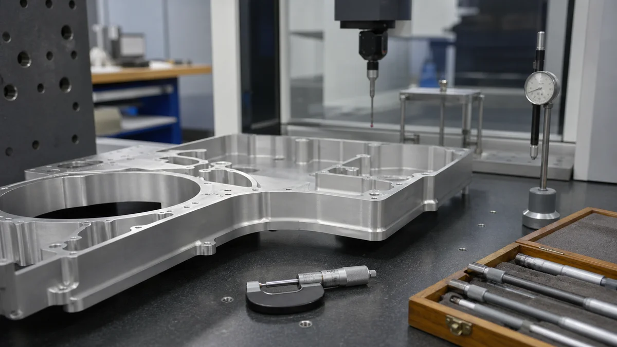
Tolerance planning should follow feature function. Bearing bores, sealing faces, dowel holes, mating surfaces, alignment features, and critical hole patterns may need closer control than clearance pockets, cosmetic edges, or non-contact faces. A tiered plan directs machining and inspection effort toward the features that affect assembly.
| Feature category | Specification method | Process risk to discuss | Inspection evidence |
|---|---|---|---|
| Functional interface | Explicit size tolerance or focused GD&T | Fixturing, tool wear, finish buildup | Actual result from the defined datum system |
| Assembly-related feature | Position, orientation, or fit control as required | Cross-setup tolerance stack-up | First-article, sampling, or selected full inspection |
| Non-critical geometry | General drawing tolerance | Unnecessary precision if individually tightened | Routine dimensional verification |
| Finish-sensitive feature | Pre- or post-finish acceptance note | Coating growth, masking boundary, final fit | Measurement in the stated finished condition |
For many non-critical aluminum features, approximately ±0.10 mm to ±0.13 mm can be a practical quoting baseline when tighter control is unnecessary. It remains dependent on geometry and supplier capability. Put the general tolerance in the title block5 or drawing notes, potentially by referencing an applicable standard such as ISO 2768, rather than repeating it on every dimension.
Requirements below about ±0.05 mm become process-and-inspection decisions. The supplier may need to consider workholding stability, tool wear, cutting sequence, machine and part temperature, and the measurement method. Broad plates, thin walls, asymmetric pockets, and relationships spanning several setups need particular review because material removal, reclamping, and datum transfer can reduce repeatability.
Use GD&T when function depends on flatness, position, perpendicularity, parallelism, coaxiality, or profile rather than size alone. Choose accessible functional datums and state the required inspection evidence. A blanket tight tolerance hides design intent and adds work without ensuring that the relationships controlling fit are actually protected.
How Should Anodizing and Other Finishes Be Specified for 6061 or 7075?
Specify anodizing or another finish by its function, location, and acceptance condition rather than assuming 6061 and 7075 respond identically. Define treated surfaces, appearance criteria, masking, electrical contacts, dimensional allowance, and whether critical dimensions apply before or after finishing.
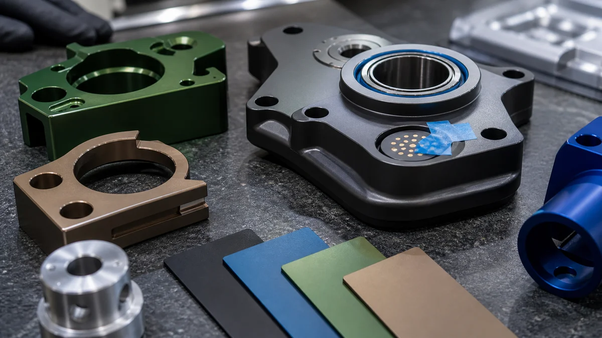
Finishing should solve a stated requirement: corrosion protection, wear resistance, appearance, coating preparation, conductivity control, or dielectric behavior. A note that says only “black anodize” does not identify the governing function, cosmetic surfaces, protected interfaces, or final inspection condition.
Before quotation, define:
- The finishing process and governing specification when one applies.
- Treated surfaces and areas that remain as machined.
- Functional and cosmetic zones, including any approved appearance sample or viewing criteria.
- Masking for bearing fits, threads, sealing faces, electrical contacts, grounding points, or adhesive areas.
- Permitted rack-mark locations where appearance or contact marks matter.
- Coating requirements that affect machining allowance or fitted dimensions.
- Whether dimensions and surface conditions apply before or after finishing.
- Inspection frequency, required records, and lot traceability when applicable.
Alloy, temper, starting surface, pretreatment, geometry, and process conditions can influence the finished appearance. Do not assume two parts with similar tool marks will look identical after treatment when one is 6061 and the other is 7075. If visual consistency matters, define it through explicit acceptance criteria or a controlled sample and request a review of the proposed alloy and preparation route.
Example: A bearing bore must remain uncoated while the exterior is anodized. The drawing should show the masking boundary and state that the bore is accepted in its specified final condition. Without that instruction, finish buildup, machining allowance, and the timing of dimensional inspection remain ambiguous.
Anodizing will not reliably hide scratches, variable cutter marks, or inconsistent blasting. Surface preparation and anodizing6 are coordinated but distinct requirements. Localize cosmetic and functional finish notes rather than applying a blanket condition to the entire part.
What Should the RFQ Include Before a Supplier Quotes 6061 or 7075?
Send a process-correct RFQ containing the model, controlled drawing, alloy, temper, stock form, quantities, production intent, loads, exposure, joining, finish, critical tolerances, inspection requirements, revision, and delivery expectations. Complete inputs let suppliers compare 6061 and 7075 without relying on hidden assumptions.
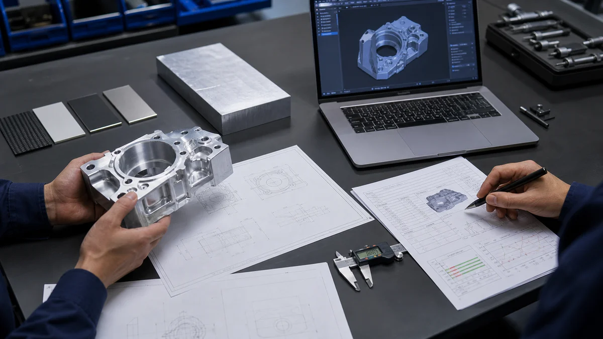
Name the intended process first. CNC machining removes material from solid stock by milling, turning, drilling, boring, reaming, and related operations. CNC turret punching7 or CNC punch press work uses programmed punch tools on sheet metal. Metal stamping cuts or forms sheet with dedicated dies. Sheet metal fabrication may combine cutting, punching, bending, welding, and finishing. Plastic injection molding forms polymer in a mold.
“CNC turret punching, CNC punch press, CNC-controlled stamping equipment, or metal stamping depending on the actual process” is not one standard process term. If it appears in a request, clarify whether it means CNC turret punching, CNC punch press work, CNC-controlled stamping equipment, sheet metal fabrication, or die stamping before discussing the material.
Use this RFQ and approval checklist:
- ☐ Current 3D CAD model showing the complete geometry.
- ☐ Controlled 2D drawing with units, part number, drawing standard, and active revision.
- ☐ Governing-document statement for any model and drawing conflict.
- ☐ Exact alloy, temper, and required stock form.
- ☐ Approved alternatives and the authority responsible for substitution approval.
- ☐ Required material documentation or traceability.
- ☐ Immediate quantity, quotation tiers, and projected usage when known.
- ☐ Prototype, validation, pilot, or repeat-production intent.
- ☐ Governing loads, fatigue concerns, deformation limits, and exposure conditions.
- ☐ Welding, fastening, assembly, and other joining requirements.
- ☐ Functional, assembly-related, cosmetic, and non-critical feature classification.
- ☐ Critical tolerances, functional datums, GD&T, and the general tolerance note.
- ☐ Surface roughness, anodizing, masking, cosmetic criteria, and pre- or post-finish dimension rules.
- ☐ Inspection method, reporting scope, sampling or first-article requirements, and measurement condition where relevant.
- ☐ Delivery expectations, partial-shipment needs, and revision stability.
Example: An RFQ for “aluminum CNC parts” that omits temper, quantity, finish, and inspection scope invites suppliers to quote different assumptions. The resulting prices may appear comparable while representing different stock, machining, finishing, and verification plans.
For a material recommendation or quotation, send the 3D model, controlled 2D drawing, proposed material grade and temper, stock form, quantity, prototype or production intent, critical tolerances, surface finish, joining method, inspection expectations, active revision, exposure conditions, and delivery requirements.
References
-
Aluminum 6061-T6 - ASM Material Data Sheet - MatWeb - Typical Mechanical Properties Hardness, Brinell 95. Strength 310 MPa 45000 psi AA; Typical Tensile Yield Strength 276 MPa 40000 psi AA; about 2% greater than ... ↩
-
Aluminum and Aluminum Alloys Subject Guide - 6061 is one of the most widely used of all aluminum alloys for general construction. The weldability of these alloys is excellent, and they have excellent ... ↩
-
Influence of Material Removal Strategy on Machining ... - PMC - by Y Li · 2023 · Cited by 14 — In this paper, the effects of material removal strategies and initial stress states on the machining deformation of aluminum alloy plates ... ↩
-
6061 Aluminum vs 7075 Aluminum: What are the ... - Conventional fusion welding is generally avoided with 7075 because cracking may occur. ↩
-
ISO 2768 Tolerance: Classes, Tables & How to Apply - ISO 2768 defines general tolerances for machined parts in 4 classes (f, m, c, v). Full tolerance tables, drawing examples, and common ... ↩
-
MIL-PRF-8625F : Anodizing - Type III coatings shall be the result of treating aluminum and aluminum alloys electrolytically to produce a uniform anodic coating on the metal surface. ↩
-
CNC Machining vs Stamping: Which Is Best for Your Project? - CNC machining removes material from a solid block using computer-controlled tools, making it ideal for complex parts and tight tolerances. Metal stamping uses ... ↩