

Choosing an inspection method for a CNC machined part begins with the drawing, not with a preference for the most advanced equipment. An accessible diameter with an independent size tolerance presents a different measurement problem from a visible edge profile or a hole pattern controlled relative to functional datums.
Hand gauges, vision systems, and coordinate measuring machines answer different specification questions. Their suitability depends on feature type, geometry, access, tolerance, inspection frequency, required documentation, production intent, and the conditions under which final measurements will be accepted.
A sound inspection plan assigns a method to each characteristic, separates production screening from dimensional audit, and defines the required evidence before quotation. The following decisions provide that characteristic-level framework.
How Do CMMs, Vision Systems, and Hand Gauges Measure CNC Parts?
Hand gauges directly measure accessible individual features, vision systems optically evaluate visible edges and profiles, and CMMs establish a coordinate system for three-dimensional relationships. Choose among them according to what the drawing controls: independent size, visible two-dimensional geometry, or features related to functional datums.
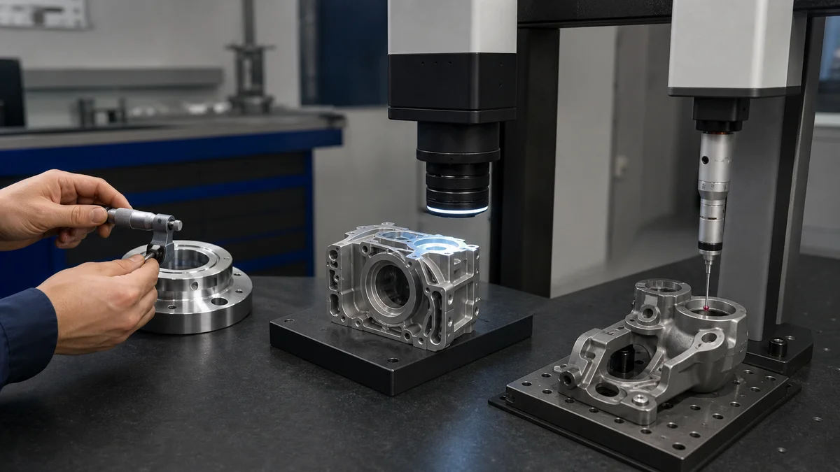
These methods are not three grades of the same inspection process. Each works from a different measurement principle, so the right choice follows the characteristic being accepted.
| Method | How it measures | Suitable characteristics | Main specification boundary |
|---|---|---|---|
| Hand gauges | Contact between an instrument and accessible surfaces | Diameters, thicknesses, lengths, depths, and defined comparative checks | Does not independently establish every relationship among multiple features |
| Vision inspection | Camera, optics, lighting, and software detect visible boundaries | Profiles, slots, radii, angles, hole outlines, and presence checks | Requires a clear optical path and repeatable edge definition |
| CMM inspection | A probe collects points within an established coordinate system | Datum-related geometry, GD&T controls, and three-dimensional relationships | Requires alignment, probe access, fixturing, programming, and suitable conditions |
A micrometer can show whether an accessible outside diameter is within its size limits. It does not establish where that diameter's axis lies relative to another bore or mounting face. A vision system can evaluate an exposed slot outline without contact, but it cannot infer a hidden wall. A CMM can align the part to specified datums and evaluate related features within the same frame.
Start by defining what the measurement must prove. Note the feature location, tolerance type, datum references, accessibility, sampling level, and required record. If no purchasing or design requirement mandates particular equipment, specify the acceptance evidence and let the supplier propose an appropriate dimensional inspection method1.
When Are Hand Gauges Enough for a CNC Machined Part?
Hand gauges may be sufficient when the drawing controls accessible diameters, lengths, depths, or thicknesses as independent sizes. The selected instrument must suit the feature and tolerance, while the inspection requirement must not depend on a shared coordinate system, hidden geometry, or formal datum-based evidence.

Hand gauging is often the direct choice when a CNC machined feature can be measured between suitable contact surfaces. A micrometer can check an outside size, a bore gauge can check an internal diameter, and a depth micrometer can check an accessible step or recess. A dial indicator may support comparative checks when the setup and reference are clearly defined.
Before assigning hand gauges, confirm that:
- The characteristic is an independent size rather than a location or orientation relative to datums.
- The instrument can contact the intended surfaces without interference.
- Contact will not mark the finish or deflect a thin wall.
- The instrument and method can resolve the specified tolerance.
- The same measurement technique can be applied consistently.
- The required sampling and actual-value records can be produced.
A frequent specification error is treating a diameter result as evidence of axis location. A bore can meet its size tolerance while its centerline is displaced relative to a mounting face or second bore. The diameter and the location are separate characteristics and may require different inspection methods.
Quantity also changes the decision. Hand gauges avoid CMM programming and alignment for a few direct checks, but repeated manual measurement and result entry can add labor when many parts or characteristics are involved. Conversely, a formal coordinate report may add work without improving acceptance of a few accessible, independent sizes. Base the choice on the characteristic, instrument suitability, inspection frequency, and reporting obligation—not on an assumption that more advanced equipment always produces a more useful result.
When Does GD&T Require CMM Inspection?
CMM inspection is usually appropriate when GD&T controls relate features to defined datums or require several features to be evaluated in one coordinate system. Position, perpendicularity, angularity, profile, and runout cannot be reduced reliably to isolated size measurements when their functional relationships govern acceptance.
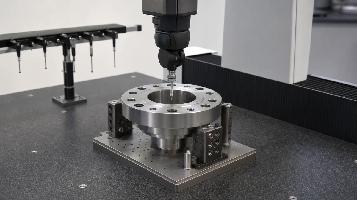
Geometric dimensioning and tolerancing separates feature size from form, orientation, and location. When acceptance depends on those relationships, the inspection method must reproduce the datum reference frame on the controlled drawing. A CMM can establish that alignment, collect points from the relevant features, and calculate the specified geometric deviation.
A feature can therefore pass its size tolerance and still fail its functional relationship. The report should show more than a general pass statement. Depending on the purchasing requirement, it may need the characteristic identifier, nominal requirement, tolerance, actual result, acceptance status, and applicable datum alignment.
Scenario: A machined flange has a bolt-hole pattern controlled by position relative to primary datum A and secondary datum B. A bore gauge can verify each hole diameter, but those readings do not show whether the pattern is correctly located or oriented. Coordinate measurement can align the flange to A and B and then evaluate the hole axes in that frame. This is a teaching scenario, not a customer case.
Does every GD&T control require a CMM?
Not automatically. The answer still depends on the control, geometry, access, tolerance, available fixtures, production intent, and evidence required. Some characteristics may be verified with a purpose-designed gauge or another suitable method. A CMM request should not replace a complete characteristic definition.
For quotation, state the drawing revision, controlled datum reference frame, characteristics requiring documented results, first-article or production sampling scope, and report format. That information lets the supplier plan the measurement program against an explicit GD&T inspection requirement2.
Which Visible 2D Features Are Suitable for Vision Inspection?
Vision inspection may suit exposed edges, profiles, slots, hole outlines, radii, angles, codes, and presence checks when lighting and contrast produce repeatable edge detection. It is not a complete replacement for CMM inspection when hidden surfaces, full three-dimensional form, or complex datum relationships determine acceptance.
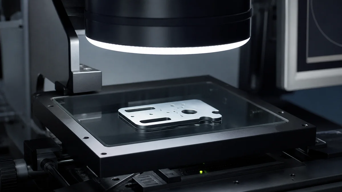
Vision systems measure boundaries that the optical arrangement can see and define consistently. The camera captures the part, lighting separates the target from its surroundings, and software identifies an edge or another visual feature. This makes the method useful when the inspection question is substantially two-dimensional and part presentation can remain stable.
Suitable candidates may include:
- Exposed slot length and width.
- A planar outside profile.
- Visible hole outlines when only planar dimensions are controlled.
- Accessible radii, angles, or edge breaks.
- Presence or absence of a specified feature.
- Repeated screening that should not apply contact force.
The drawing must distinguish an optical boundary from the complete feature requirement. A circular opening in a top view does not prove bore depth, cylindricity, axis direction, or location relative to a hidden datum. An exposed outline also says nothing about an obscured underside unless another view or method addresses it.
Edge definition3 is a specification issue, not merely a software setting. Reflective machined surfaces, transparent materials, weak contrast, burrs, shadows, inconsistent surface finish, and variable fixturing can shift the detected boundary. Where a chamfer or radius meets a face, identify which visible transition controls the dimension. Otherwise, the buyer and supplier may measure different edges while both believe they followed the drawing.
For repeat production, separate optical measurement candidates from presence-only checks and from features requiring a dimensional audit by another method. State whether the system must record actual values, pass/fail results, or both.
When Should a Delicate CNC Part Be Inspected Without Contact?
Non-contact vision inspection deserves consideration when a thin, soft, small, or surface-sensitive CNC part could be marked, deflected, or distorted by contact. The critical feature must still be optically visible and measurable; surface reflectivity, transparency, weak contrast, or recessed geometry may limit the method.

Contact force can change the very feature being measured. Thin walls may deflect, soft engineering plastics may deform, and cosmetic or finish-critical surfaces may be marked through handling. A non-contact method avoids loading the feature and may better represent the part in its free state4.
The benefit is conditional. Vision still needs a stable optical boundary. Polished metal can create glare, transparent plastic can produce ambiguous edges, and low contrast can make detection sensitive to lighting or background. Controlled lighting and fixturing may improve the image, but the supplier must review the actual material grade, surface finish, wall thickness, geometry, and feature orientation.
Example: Consider a thin machined polymer washer with an outside profile, an internal opening, and a scratch-sensitive display face. Vision inspection may measure both visible outlines without contact marks or wall distortion. If the drawing also controls parallelism between its faces or the opening axis relative to a functional datum, a second method may still be necessary. This is a specification example, not a verified production case.
State whether non-contact inspection is mandatory or merely preferred. Identify delicate surfaces, permitted handling zones, critical visible edges, and whether dimensions apply in a free or restrained condition. Also call out any coating or finish that changes reflectivity or edge contrast.
Where the part combines sensitive visible profiles with datum-controlled three-dimensional features, a mixed plan is usually more defensible than asking vision to prove geometry it cannot see.
Can the Inspection Tool Reach or See Every Critical Feature?
Select inspection equipment only after confirming physical or optical access to every critical feature. Hand gauges need suitable contact surfaces, vision needs an unobstructed line of sight, and CMMs need a workable probe path, stylus arrangement, datum access, and fixture that does not conceal required geometry.

A method can fit the tolerance in principle yet fail because the feature cannot be reached, seen, or held correctly. The supplier needs the full 3D model and controlled drawing to determine how the part will be supported, which surfaces establish alignment, and whether the measuring element can approach without collision or obstruction.
| Geometry condition | Hand-gauge access issue | Vision access issue | CMM access issue |
|---|---|---|---|
| Deep bore | Contact alignment and usable depth | Internal wall may not be visible | Stylus length, internal clearance, and probe path |
| Recessed pocket | Instrument body may block contact | Pocket walls can obscure boundaries | Probe approach and fixture clearance |
| Thin wall | Contact can deflect the surface | Visible edge may be measured without loading | Probing force and support need review |
| Intersecting holes | Individual contact may be restricted | Hidden intersection cannot be seen directly | Reach and feature construction must be planned |
| Obstructed datum | Reference surface may be inaccessible | Camera may lack line of sight | Fixture must expose enough datum area for alignment |
A cropped view can conceal internal steps, counterbores, undercuts, restricted openings, or wall thickness that controls measurement feasibility. Section views help, but the complete model gives the supplier a better basis for checking competing approach paths.
Fixturing also affects the result. Supporting a thin part may improve repeatability while restraining natural shape; the fixture may also cover a datum or critical surface. State whether the characteristic applies in a free state, an assembled state, or a defined fixture condition.
If particular equipment is mandatory, disclose that before quotation. Early probe access review5 can reveal whether a different stylus arrangement, optical orientation, purpose-designed gauge, or revised inspection sequence is required.
Where Should Final Dimensional Inspection Take Place?
Final inspection should occur under measurement conditions appropriate to the tolerance, material, part condition, and governing acceptance requirement. A controlled room can reduce temperature, coolant, and vibration influences, while production-area inspection may shorten feedback time but requires an environment suitable for the selected method.
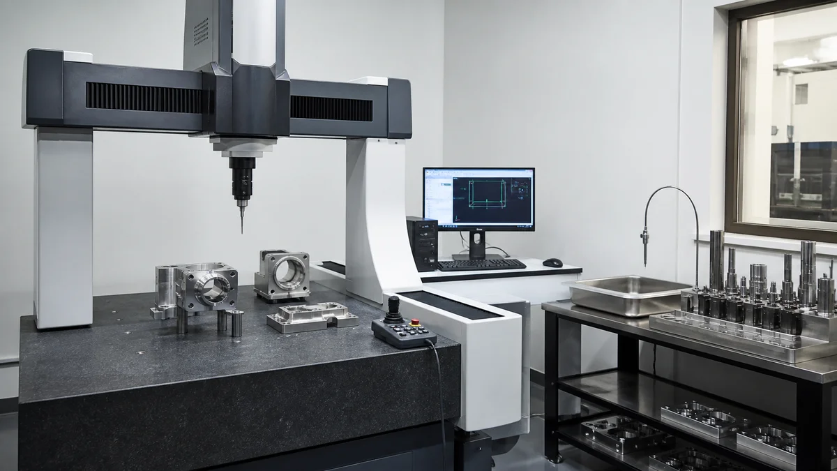
Measurement location affects both result credibility and manufacturing flow. A controlled inspection area can separate the part from machine heat, coolant residue, chips, vibration, and rapid environmental change. That control may matter when tolerances are close, dimensions are sensitive to temperature, or buyer and supplier results may be compared near a limit.
Moving parts away from production adds cleaning, identification, transport, stabilization, and re-fixturing. Production-area gauging or vision screening can provide faster process feedback, provided the environment is suitable for the characteristic and method. It should not automatically become the final acceptance condition.
Before quotation, define:
- Whether dimensions apply immediately after machining or after stabilization.
- Whether the part is measured clean, dry, coated, heat-treated, or otherwise in its delivered condition.
- The location and part condition that govern final acceptance.
- Any environmental requirement stated by the controlling specification.
- Whether measurement occurs free, restrained, or assembled.
- The procedure for comparing results close to a tolerance limit.
- The equipment and inspection-record identification required in the report.
Hand-gauge readings can change with alignment, contact pressure, and operator technique. Vision can be influenced by lighting, contamination, vibration, and presentation. CMM results depend on datum alignment, probing strategy, fixture condition, and environment.
A clear measurement condition prevents one party from checking a warm, recently machined part while the other checks a cleaned and stabilized part. The inspection state is therefore part of the tolerance agreement, not merely an internal shop preference.
Should Screening and Dimensional Audit Use Different Methods?
Screening and dimensional audit may use different methods because they answer different questions. Vision can check every part for stable visible conditions, while hand gauges or a CMM can record sampled dimensional evidence for selected characteristics. The RFQ must define coverage, frequency, actual-value reporting, and approval responsibilities.
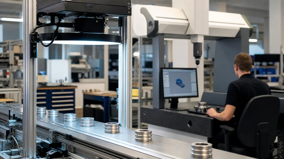
Screening asks whether each inspected part shows a defined condition. A dimensional audit records evidence that selected characteristics conform to the controlled drawing. Separating those purposes often produces a clearer plan than forcing one instrument to handle every characteristic.
| Inspection task | Candidate method | Scope that must be specified | Required evidence |
|---|---|---|---|
| Visible feature presence | Vision | Characteristics checked on every part | Screening result and rejection rule |
| Repeated exposed profile | Vision | Edge definition and coverage | Pass/fail record or actual values |
| Accessible diameter or depth | Hand gauge | Sample size and frequency | Actual result and instrument identification if required |
| Datum-related hole pattern | CMM | Datum frame and sampled parts | Geometric result and report scope |
| Periodic audit of screened features | Suitable dimensional method | Audit interval and reaction plan6 | Recorded values and disposition route |
Scenario: A stable production part has a visible slot, an accessible thickness, and mounting holes controlled from datums. Vision could screen slot presence and outline, a micrometer could sample thickness, and a CMM could periodically verify the hole pattern. This teaching scenario illustrates task separation; it is not a reported customer program.
Avoid the phrase “100% inspection” unless it identifies the characteristics included. Complete screening of one visible feature is not complete dimensional inspection of the part. A sampled CMM report likewise does not show that every delivered part was measured.
Define which characteristics receive complete screening, which are sampled, which need actual values, and which require formal coordinate results. Add the reaction plan for a failed screen or audit, including segregation, reinspection, documented disposition, or buyer review. Those decisions affect validation, labor, reporting, and quotation scope.
What Drives Inspection Cost and Lead Time?
Inspection cost and lead time depend on characteristic count, tolerance, feature access, quantity, sampling, programming, fixturing, environmental control, operator labor, and report detail. The lowest instrument time is not always the lowest total cost, and the most sophisticated method is not automatically the best value.
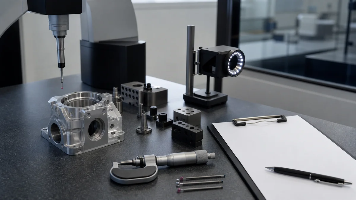
The inspection quote should reflect the complete measurement route rather than the perceived status of the equipment. Each method combines initial preparation with recurring work in a different way.
| Cost or schedule driver | Hand gauges | Vision inspection | CMM inspection |
|---|---|---|---|
| Initial setup | Instrument selection and work instructions | Lighting, fixturing, programming, and validation | Fixture, datum alignment, probe program, and report setup |
| Recurring effort | Handling, measurement, and result entry | Part loading and monitoring after setup | Loading, alignment, probing cycle, and report handling |
| Geometry constraint | Contact access and alignment | Line of sight and edge contrast | Probe access, datum exposure, and stylus arrangement |
| Documentation | Manual or digital recorded values | Screening records or optical measurements | Characteristic-level coordinate results |
| Workflow effect | Direct for a few accessible checks | Useful for stable repeated visible tasks | May require cleaning, stabilization, transport, and controlled measurement |
Quantity matters, but there is no universal breakpoint. A prototype lot with a few accessible sizes may suit hand gauges. Stable repeat demand may justify vision setup. A first article with multiple datum-controlled characteristics may need CMM inspection even when only a few parts are ordered.
Documentation can influence effort as much as the measurement itself. Recorded actual values for every critical characteristic differ from a pass/fail screen. A ballooned first-article package differs from periodic sampling. Adding a formal CMM report after quotation can introduce programming, alignment, and reporting work that was not priced initially.
For comparable quotations, provide realistic quantity, prototype or production intent, characteristic count, tolerance type, inspection frequency, sampling plan, and required records. This exposes the actual inspection cost drivers7 without relying on unsupported price or lead-time assumptions.
Why Should Inspection Be Chosen by Characteristic Rather Than Part Complexity?
Inspection should be selected characteristic by characteristic because overall part complexity does not reveal the actual measurement problem. A visually complex component may need only independent size checks, while a simple-looking plate may require coordinate inspection when hole location, orientation, or profile is controlled from datums.

Part appearance is a poor basis for specifying metrology. The real inspection risk comes from the tolerance definition, functional relationship, feature access, surface condition, reporting obligation, and production plan.
Common specification mistakes include:
- Requiring a complete CMM report because the part has many pockets, although acceptance covers only accessible independent sizes.
- Using a bore gauge to accept a hole whose axis position is controlled relative to datums.
- Treating a top-view vision result as proof of bore depth, internal form, or an obscured underside feature.
- Applying one inspection method to every characteristic without considering access or function.
- Requesting “full inspection” without stating whether that means every drawing characteristic, every critical feature, or every produced part.
Example: A rectangular machined plate may look simple, yet its mounting-hole pattern can be controlled by position relative to a primary face and two locating edges. Checking hole diameter and individual edge distances does not necessarily evaluate the defined datum relationship. Conversely, a sculpted cover may look complex while requiring documented measurement of only a few accessible mating features. This is a teaching example, not a customer case.
Classify each requirement as size, form, orientation, location, profile, surface finish, visual condition, or presence. Then record access, datum dependence, sampling frequency, actual-value needs, and the approval document required.
This characteristic-level inspection plan8 allows different methods on the same part. A CMM may verify a critical datum relationship, hand gauges may handle ordinary diameters, and vision may screen exposed edges. The result is tied to function instead of visual complexity.
How Does the Manufacturing Process Change the Inspection Plan?
The inspection plan must reflect how the part is manufactured because CNC machining, CNC turret punching, metal stamping, sheet metal fabrication, and plastic injection molding create different feature relationships and variation risks. Identify the actual process before defining datums, measurement condition, sampling, and acceptance evidence.
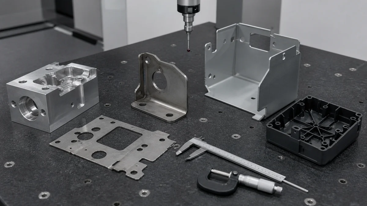
The same measurement technology may appear across several manufacturing processes, but the characteristics and final inspection conditions9 are not interchangeable.
| Manufacturing process | How the part is made | Process-specific inspection focus |
|---|---|---|
| CNC machining | Removes material by milling, turning, drilling, boring, reaming, or related operations | Bores, faces, pockets, tool access, setup relationships, datums, and machined finish zones |
| CNC turret punching or CNC punch press work | Uses programmed physical tools on sheet | Hole patterns, cut edges, formed details, burr direction, flatness, and sheet condition |
| Metal stamping | Cuts or forms sheet with dedicated dies | Die-related relationships, material flow, formed geometry, burrs, and repeat-production condition |
| Sheet metal fabrication | May combine cutting, punching, bending, welding, hardware insertion, and finishing | Bend dimensions, springback, weld condition, assembly datums, and final flatness |
| Plastic injection molding | Fills a mold with polymer, then cools and ejects the part | Shrinkage, warpage, draft, gate-influenced areas, wall thickness, cavity variation, and final molded dimensions |
“CNC turret punching, CNC punch press, CNC-controlled stamping equipment, or metal stamping depending on the actual process” is not one standard process term. An RFQ using it should clarify whether the route is CNC turret punching, a CNC punch press, other CNC-controlled stamping equipment, or general metal stamping with dedicated dies. That distinction changes tooling, geometry, variation sources, and inspection timing.
A hole punched into a flat blank may move relative to formed faces after bending because the final geometry includes bend sequence and springback. State whether the hole is accepted in the flat or formed condition. For molded plastic, wall thickness, draft, cooling, and gate location can affect shrinkage or warpage; inspect the delivered molded condition rather than treating it like stock-machined plastic.
Name the manufacturing route and delivered state before assigning hand gauges, vision, or CMM inspection. This prevents suppliers from quoting different process and acceptance assumptions.
What Inspection Information Belongs in a CNC Part RFQ?
A quote-ready CNC inspection RFQ should define the part, controlled revision, material, quantity, production intent, critical characteristics, datums, finish, measurement condition, sampling, reports, and delivery expectations. Specify mandatory equipment only when required; otherwise, define the acceptance evidence and let the supplier propose a suitable method.
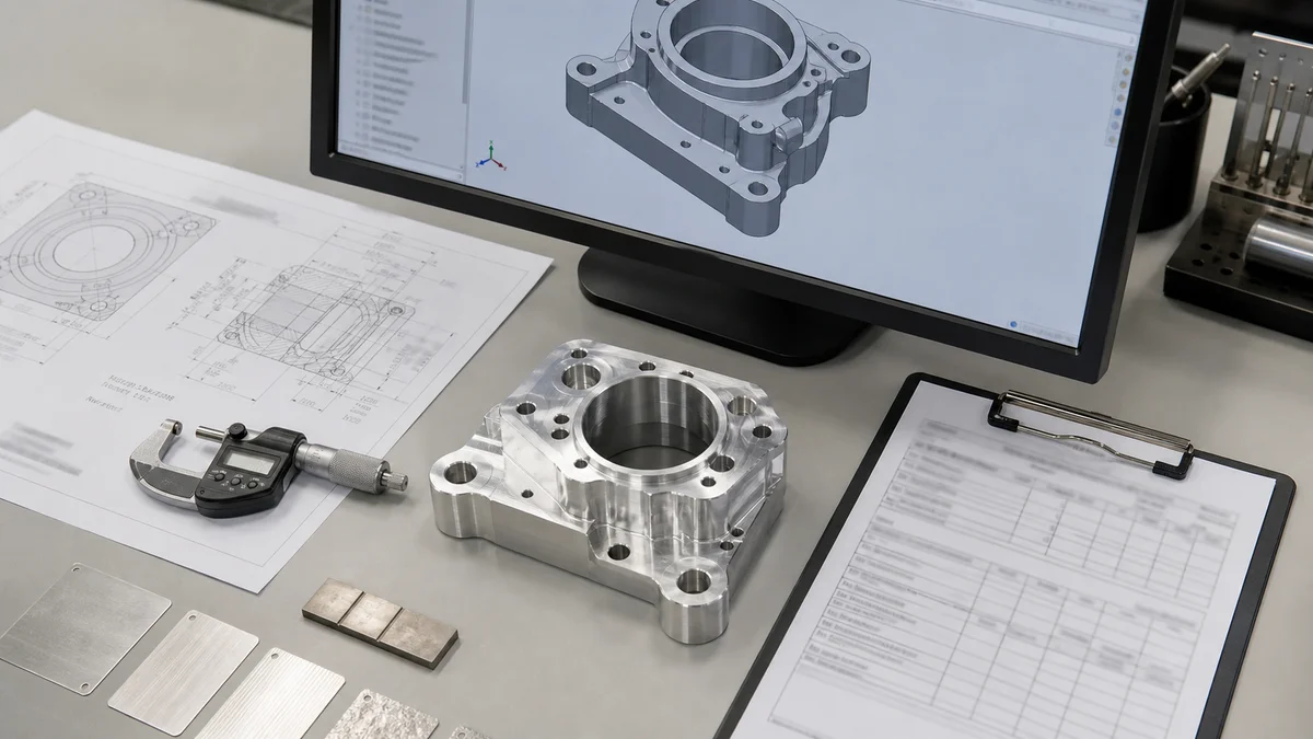
Inspection requirements belong in the RFQ because programming, fixturing, handling, reporting, and approval work affect the manufacturing plan. A complete package should connect every required result to the correct part, drawing revision, and delivered condition.
CNC part inspection RFQ and approval checklist
- ☐ Current 3D model showing complete internal and external geometry.
- ☐ Controlled 2D drawing with the active revision level.
- ☐ Statement identifying whether the model or drawing governs if they conflict.
- ☐ Exact material grade and condition.
- ☐ Quantity, lot size, and repeat demand relevant to inspection planning.
- ☐ Prototype, first production run, bridge production, or repeat-production intent.
- ☐ Critical dimensions, size tolerances, GD&T controls, and functional datum reference frames.
- ☐ Surface finish requirements, locations, and whether dimensions apply before or after any coating or treatment.
- ☐ Thin, soft, reflective, transparent, cosmetic, or scratch-sensitive areas.
- ☐ Views exposing deep bores, recesses, hidden surfaces, and restricted access.
- ☐ Characteristics requiring complete screening, sampling, or periodic audit.
- ☐ Required actual values, pass/fail records, dimensional reports, CMM results, or ballooned first-article records.
- ☐ First Article Inspection scope, sample expectation, and approval timing when required.
- ☐ Governing measurement condition, including stabilization, restraint, free-state requirements, and final finish state.
- ☐ Required instrument identification or traceability fields when the purchase requirement calls for them.
- ☐ Delivery expectations for both parts and inspection documents.
Do not use “CMM inspection required” as the entire quality instruction. Identify the characteristics, datum alignment, sampling, and evidence the CMM must provide. Likewise, “100% inspection” should identify exactly which characteristics are checked on every part.
A complete CNC machining RFQ10 lets suppliers assign hand gauges to accessible sizes, vision to suitable visible features, and CMM inspection to datum-based relationships without inventing acceptance assumptions.
For an inspection recommendation, sample plan, or quotation, send the 3D model, controlled 2D drawing, material grade, quantity, prototype or production intent, critical tolerances and datums, surface finish, inspection expectations, required reports, revision level, measurement conditions, and delivery requirements.
References
-
Dimensional Measurement Services | NIST - Engineering Metrology Toolbox-An array of tools available to help metrologists achieve high-accuracy dimensional measurements traceable to national and ... ↩
-
Advanced GD&T Techniques | Design for Inspection - ASME Y14.5-2009, on page 52. The most commonly used GD&T callouts are profile and position. less often we call out perpendicularity. There are no datums in the ... ↩
-
Dimensional Metrology Group | NIST - DMG's Dimensional Measurement Services program provides among the lowest uncertainty dimensional measurements and calibrations in the world—our best length ... ↩
-
Dimensioning and Tolerancing of Flexible Parts - We use ASME Y14.5-2009 as our standard for rigid and nonrigid parts (subject to free state variation - like sheet metal parts, etc) ↩
-
What Is CMM Programming? How It Automates Part Inspection - A coordinate measuring machine, or CMM, CMM programming converts engineering drawings, CAD models, GD&T requirements, and inspection plans into ... ↩
-
Dimensional Inspection Planning Methodologies - An international standard on product data representation and exchange for dimensional inspection planning is being developed. This paper provides a review ... ↩
-
Inspection Services - The spectrum of inspection capabilities includes dimensional layout and reporting, in-process inspection, sorting services, SPC data collection, and CMM ... ↩
-
The ASME Y14.5 GD&T Standard - Depending on the profile shape and datums referenced, profile tolerances can control size, form, orientation, and/or location. ↩
-
Precision Sheet Metal Fabrication Services: Achieving + - ... precision CNC machining, Sheet metal manufacturing, 3D printing, Injection molding. Metal stamping,and other one-stop manufacturing services. ↩
-
CNC Machining RFQ Template Guide - uneed - CNC Machining RFQ Template Guide: Get faster quotes! Use our checklist for tolerances, parts, and materials. Simplify your CNC machining quoting process. ↩