
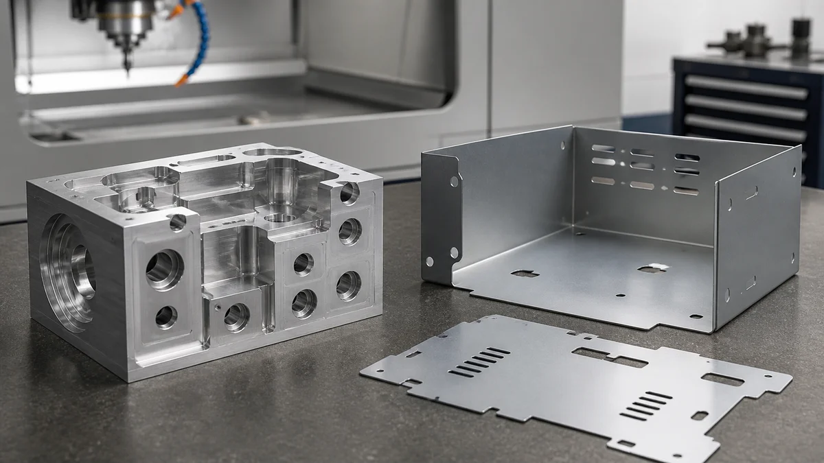
CNC machining and sheet metal fabrication can produce similar-looking metal parts, but they create geometry in fundamentally different ways. Machining removes material from solid stock. Sheet metal fabrication cuts and forms substantially uniform-thickness material, often followed by hardware insertion, welding, or mechanical assembly.
The better route depends on geometry, material grade, thickness strategy, critical tolerances, surface finish, assembly state, quantity, and revision risk. A bent bracket may clearly favor fabrication, while a compact housing with precision bores and localized thick sections may be more practical to machine.
The decisions below compare both routes at specification level, including the option to fabricate the main structure and machine selected interfaces afterward.
How Do CNC Machining and Sheet Metal Fabrication Differ?
CNC machining removes material from solid stock to create three-dimensional features, while sheet metal fabrication cuts and forms substantially uniform-thickness sheet. Their geometry, tooling, tolerance paths, and assembly requirements differ, so the intended process must be identified before suppliers can prepare comparable quotations.
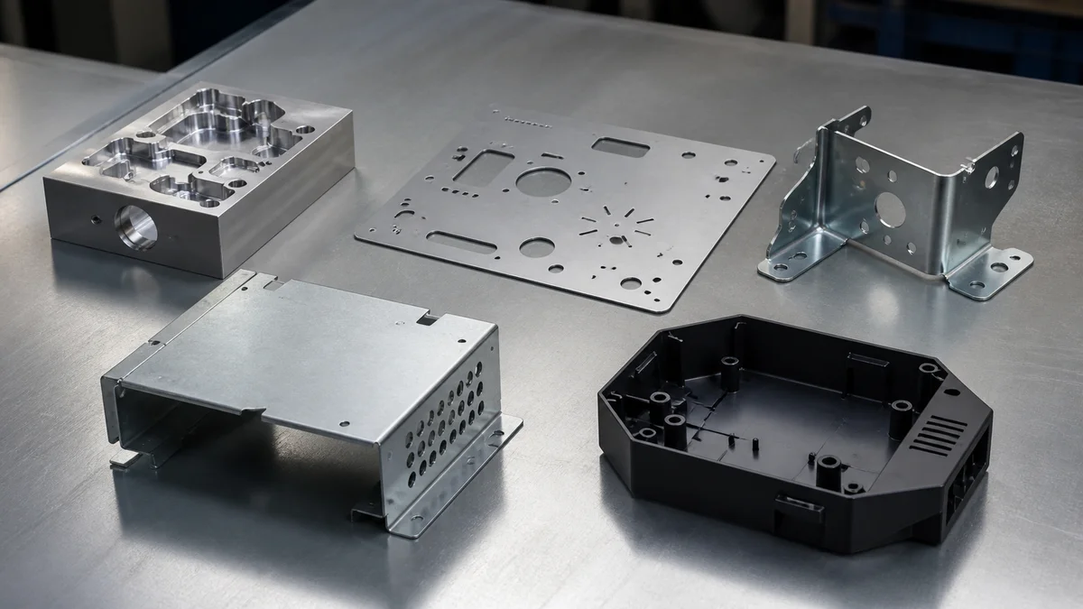
CNC machining includes milling, turning, drilling, boring, reaming, and related material-removal operations. Starting stock may be billet, bar, or plate. Cutters create pockets, bores, threads, faces, and localized thickness changes, provided the tool, holder, fixture, and machine orientation can reach the geometry.
Sheet metal fabrication starts with sheet of a specified material grade and gauge. Its route may include profile cutting, bending, forming, hardware insertion, welding, deburring, assembly, and finishing.
| Process | Starting material and action | Specification details that matter |
|---|---|---|
| CNC machining | Solid stock; material is removed | Tool access, setups, datums, bores, pockets, surface finish |
| Sheet metal fabrication | Uniform-thickness sheet; blanks are cut and formed | Gauge, bends, springback, joints, hardware, flatness, burr direction |
| CNC turret punching | Sheet; programmed punch tools cut or form features | Punch geometry, tool access, formed details, burr side |
| Metal stamping | Sheet; dedicated dies cut or form parts | Stable geometry, die commitment, production demand |
| Plastic injection molding | Polymer; molten material fills a mold | Molded geometry, material selection, tooling and production intent |
“CNC turret punching, CNC punch press, CNC-controlled stamping equipment, or metal stamping depending on the actual process” is not a standard process name. It may be intended to mean CNC turret punching, CNC punch press work, CNC-controlled stamping equipment, or general metal stamping. Replace it in the RFQ with the actual operation. Plastic injection molding remains a separate polymer process and should not be presented as a type of metal fabrication.
The practical distinction is the material transformation1: a machining plan removes stock to reveal the part, whereas a fabrication plan preserves sheet thickness while changing profile and shape.
Which Process Fits the Part’s Dominant Geometry?
CNC machining generally fits solid three-dimensional geometry with pockets, precision bores, turned features, or thickness changes. Sheet metal fabrication generally fits brackets, covers, chassis, panels, and enclosures that obtain their shape from cut profiles, bends, formed details, and joined sections.
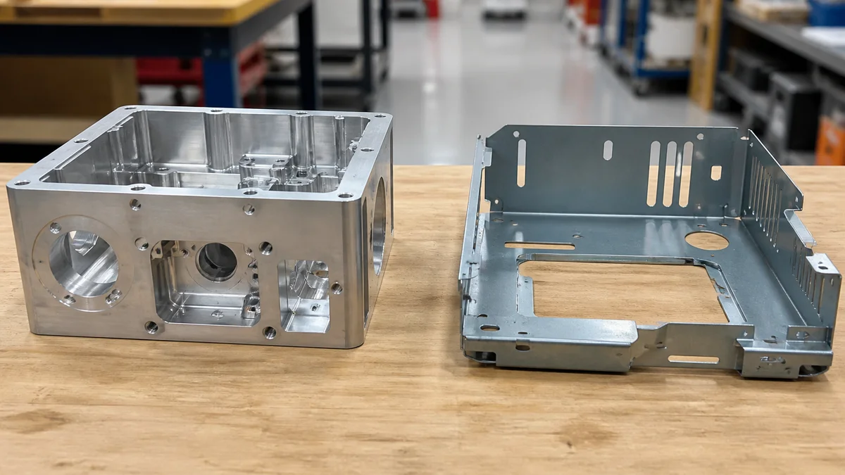
Classify the part by how it carries load, locates mating components, and creates its working envelope. A machined part need not have every surface under close control, but its dominant geometry normally depends on removing material from a solid form. A fabricated part need not remain flat, but its geometry should remain compatible with a substantially constant gauge.
Features that may favor CNC machining include:
- Precision bores, bearing seats, sealing faces, or locating holes.
- Deep or localized pockets that cannot be replaced by open construction.
- Turned diameters or other rotational geometry.
- Significant thickness changes within one component.
- Closely controlled relationships between several faces.
Features that may favor sheet fabrication include:
- Brackets shaped by one or more bends.
- Covers, guards, chassis, panels, and enclosures.
- Broad surfaces where low mass matters more than solid section thickness.
- Cutouts, formed details, inserted hardware, and joined corners.
- Assemblies that divide naturally into practical flat blanks.
Example: A rectangular electronics enclosure looks three-dimensional after assembly, but its dominant geometry may still be flat panels and bent flanges. A compact housing with a precision bore, recessed sealing face, and different wall sections is more likely to depend on solid-stock geometry.
Use a complete 3D model to show internal cavities, bend regions, mounting interfaces, and thickness transitions. The controlled 2D drawing should identify functional features and datums2. Otherwise, the supplier must infer process fit from the external shape, which hides the geometry that often determines setup count and inspection effort.
Can a Uniform Sheet Gauge Deliver the Required Function?
Sheet metal fabrication is suitable when one substantially uniform gauge can provide the required structural, enclosure, mounting, and assembly functions. CNC machining becomes more relevant when the part depends on localized thick sections, deep pockets, precision interfaces, or geometry that bending and joining cannot reproduce efficiently.
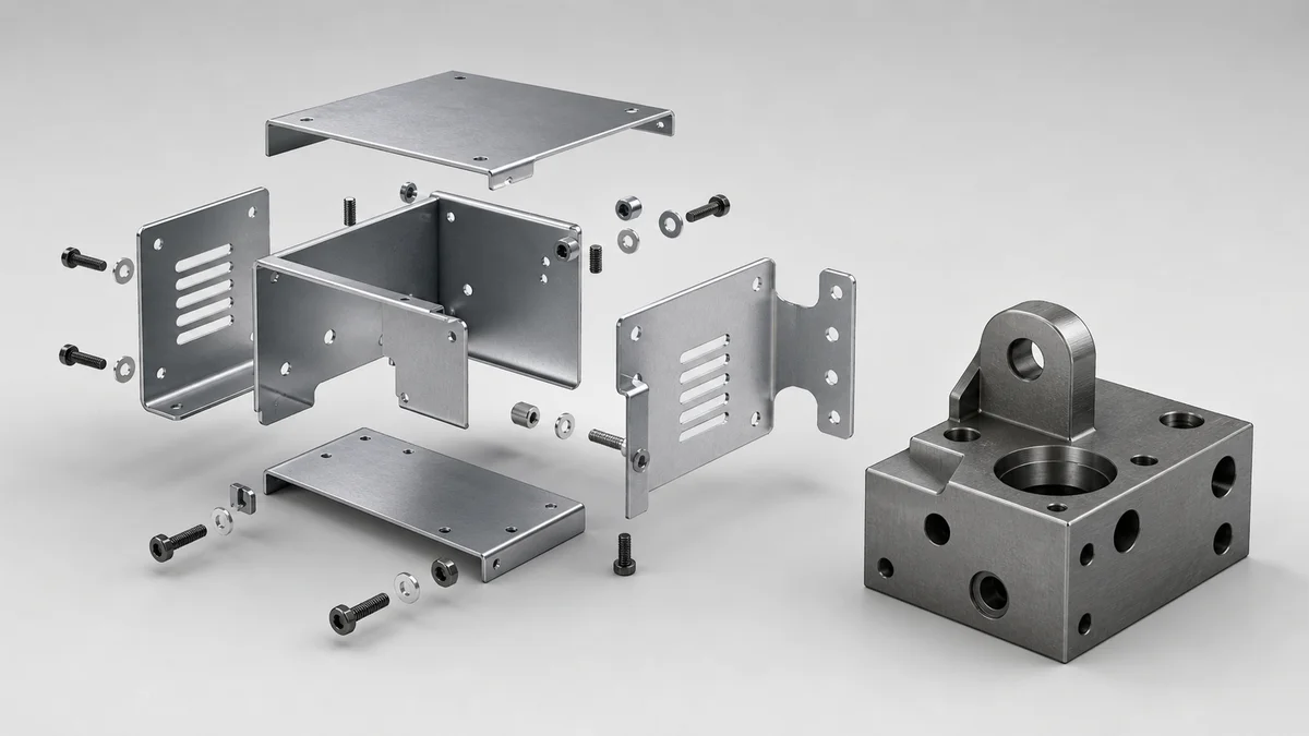
Gauge is the specified thickness of the starting sheet. A fabricated component can gain stiffness through bends, flanges, ribs, returns, or joined sections without becoming a solid block. The real question is whether those features satisfy the load path and assembly requirements while preserving practical forming, fastening, finishing, and inspection access.
Review a uniform-gauge proposal against these points:
- How loads pass through flat areas, bends, flanges, and joints.
- Whether hardware interferes with bends or mating components.
- Whether welds or fasteners are acceptable in service.
- Whether cosmetic surfaces can tolerate the joining and finishing route.
- Whether critical interfaces remain stable after forming and assembly.
CNC machining may be more direct when the component requires a thick boss around a bore, a recessed sealing land, a deep enclosed pocket, or accurately related features on different levels. Fabrication can sometimes recreate those features with plates, spacers, welded blocks, or inserted hardware, but every addition creates another tolerance path and assembly operation.
Scenario: A solid mounting block is redesigned as bent sheet solely to reduce stock removal. The revised design then needs a welded reinforcement, inserted threads, and secondary machining on a locating face. This teaching scenario does not prove that fabrication is wrong; it shows why the complete route must be compared before approving the redesign.
Specify the exact material grade and sheet gauge rather than writing only “steel” or “aluminum.” If alternatives are acceptable, define the required final properties and invite a design-for-manufacturing review3 instead of leaving substitution authority unclear.
Do Tool Access or Bend Constraints Control Feasibility?
Feasibility depends on whether machining tools can reach every required feature or sheet material can be cut and formed without impractical interference. Review cutter approach, holder clearance, workholding, bend access, springback, nearby features, burr direction, and joining sequence before treating either route as straightforward.
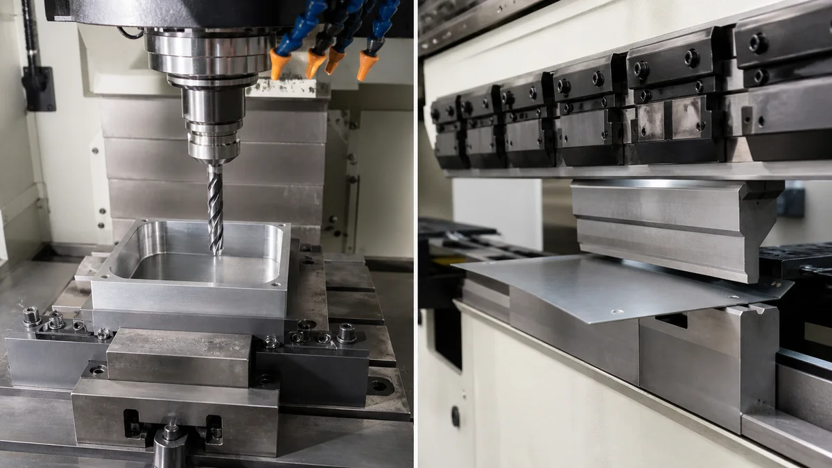
Machining access is not defined by a pocket or hole alone. The cutter, tool holder, fixture, and approach direction all need clearance. Deep pockets, narrow openings, undercuts, obstructed bores, and features spread across several faces can require longer tools, additional setups, or revised geometry. Reorientation also changes how datums transfer between operations.
For machining, check whether:
- The cutter and holder can approach without collision.
- Internal corners are compatible with a rotating cutter.
- Deep features require long, less rigid tooling.
- Critical relationships cross between setups.
- Workholding covers or distorts an important surface.
Sheet metal has a different constraint set. Bends need tooling access and room for the workpiece to move during forming. Features near a bend may distort or shift. Springback is the partial elastic return after the forming load is removed; it changes the resulting angle and must be considered in the bend plan.
Burr direction is equally practical. Cutting can leave a raised edge on one side of the blank. If that side faces a gasket, sliding component, cosmetic surface, or handling edge, assembly or finish acceptance can be affected. Mark the required burr side when function depends on it.
For fabrication, identify bend lines, bend sequence, formed details, hardware locations, weld access, cosmetic faces, and edge requirements. Supply the finished model and relevant flat-pattern information, but let the fabricator confirm production bend allowances.
A frequent specification mistake is providing only the exterior model. Section views and controlled details expose hidden pockets, tool approach restrictions, and bend interference before quotation.
How Should Tolerances Change with the Manufacturing Route?
Tolerances should follow the route that creates each feature. Machined relationships depend on tool access, workholding, and setup changes, while fabricated dimensions can accumulate variation through cutting, bending, springback, welding, and assembly. Reserve close control for features affecting fit, sealing, alignment, or performance.
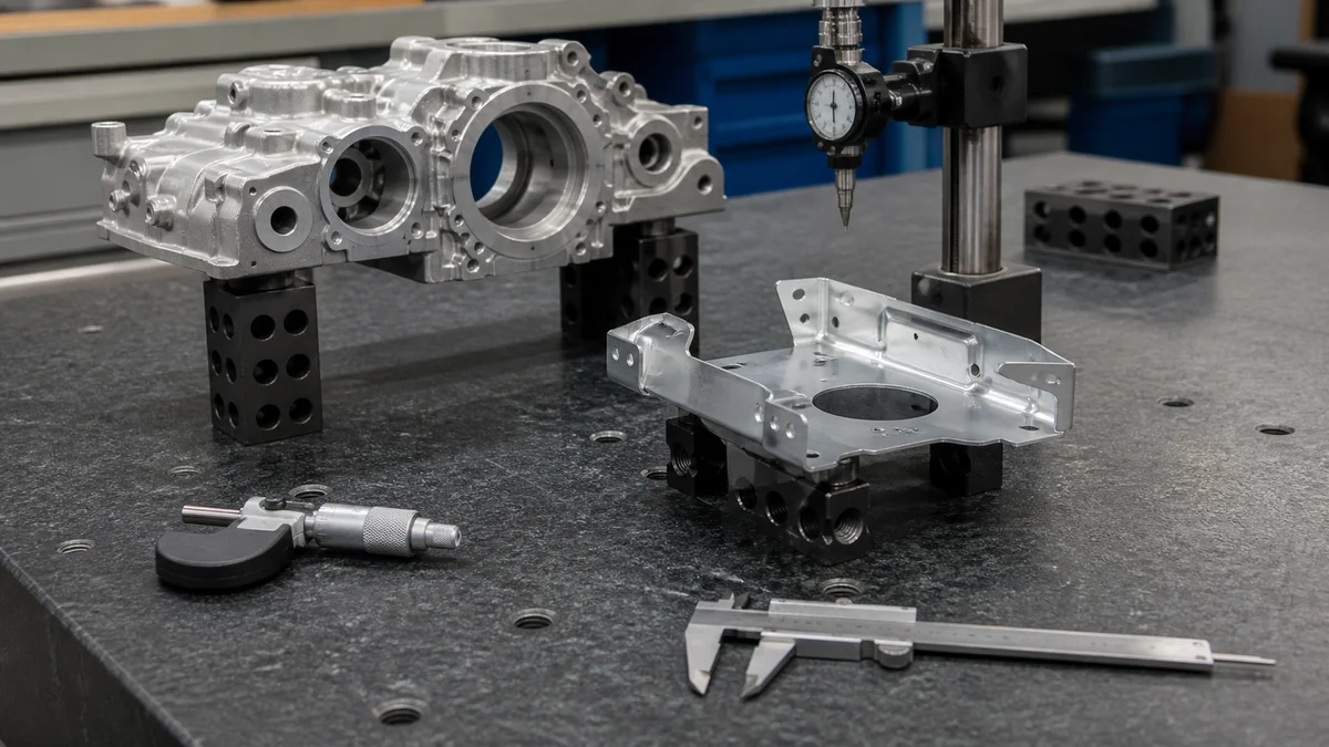
Tolerance difficulty is feature-specific. A bore and mating face produced in one machining setup may be easier to relate than features created after reclamping. In fabrication, a hole located from a flat blank edge follows a different tolerance path from one measured across several formed flanges.
| Functional requirement | CNC machining risk | Sheet fabrication risk | Drawing response |
|---|---|---|---|
| Bore or fitted hole | Tool condition, rigidity, setup transfer | Hole movement after forming | Define final size, datum, and inspection state |
| Hole-pattern location | Cross-setup alignment | Bend sequence and springback | Apply position from functional datums |
| Flat mating face | Stock stress, clamping, material removal | Forming, welding, assembly distortion | Specify final-state flatness only where needed |
| Sealing interface | Machining and finish sequence | Joint design or secondary machining | Mark the controlled surface and final condition |
| Assembly envelope | Multi-face relationship | Accumulation across bends and joints | Control the interfaces that drive fit |
Separate functional, assembly-related, cosmetic, and non-critical features. Bearing bores, sealing faces, locating holes, mounting patterns, and mating surfaces may justify close control; clearance cutouts and hidden non-contact edges often do not.
GD&T can express position4, flatness, perpendicularity, parallelism, or profile when a simple size tolerance does not protect function. Datums should reflect how the component assembles and how it can reasonably be inspected.
Example: A mounting hole cut before bending may shift relative to a mating flange. If its final location controls assembly, dimension it from functional datums in the formed state. The supplier can then decide whether forming control is sufficient or post-bend machining is warranted. Blanket tight tolerances do not repair an undefined process path.
What Inspection Scope Does Each Process Require?
Inspection should verify the features and final condition that control acceptance, rather than applying one method to every characteristic. Machined parts may emphasize bores, faces, and datum relationships; fabricated parts may require checks after bending, welding, hardware insertion, finishing, or final assembly.
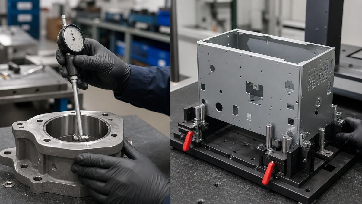
Define inspection with the tolerances, not after production planning. The supplier needs to know what must be measured, when measurement occurs, how frequently results are recorded, and what evidence accompanies delivery. A dimension checked on a flat blank cannot confirm the same relationship after bending and welding.
For machined parts, inspection may cover:
- Bore size, position, and alignment.
- Sealing or mating faces.
- Flatness and orientation from functional datums.
- Threads, pockets, and cross-face relationships.
- Controlled surface-finish zones.
For fabricated parts, it may cover:
- Material grade and gauge.
- Formed angles and final-state flatness.
- Hole locations after bending.
- Hardware type, position, and orientation.
- Specified weld or assembly condition.
- Burr direction, edge condition, and cosmetic zones.
The inspection method should match feature risk and access. Calipers or micrometers may suit accessible size checks; geometric relationships, hole patterns, or assembled structures may require a structured coordinate or fixture-based method. The drawing should define the characteristic and datum frame before it prescribes how to measure it.
State whether the order needs first-article inspection5, in-process checks, batch sampling, final dimensional reporting, or documented checks of selected critical features. A hybrid component machined after forming should be verified from its post-form datums after machining and any finish that affects acceptance.
Common specification mistake: The drawing requires a hole pattern to align in the completed enclosure, but the purchase requirement requests inspection only on the flat blanks. That evidence cannot demonstrate final alignment. Inspect the state in which the feature performs its function.
Should the Part Be Machined as One Piece or Fabricated as an Assembly?
Choose between one-piece machining and fabricated assembly by comparing material use, weight, joints, hardware, tolerance stack-up, finishing, inspection, and service requirements. A consolidated machined part can simplify interfaces, while a fabricated assembly can avoid removing large amounts of solid stock.
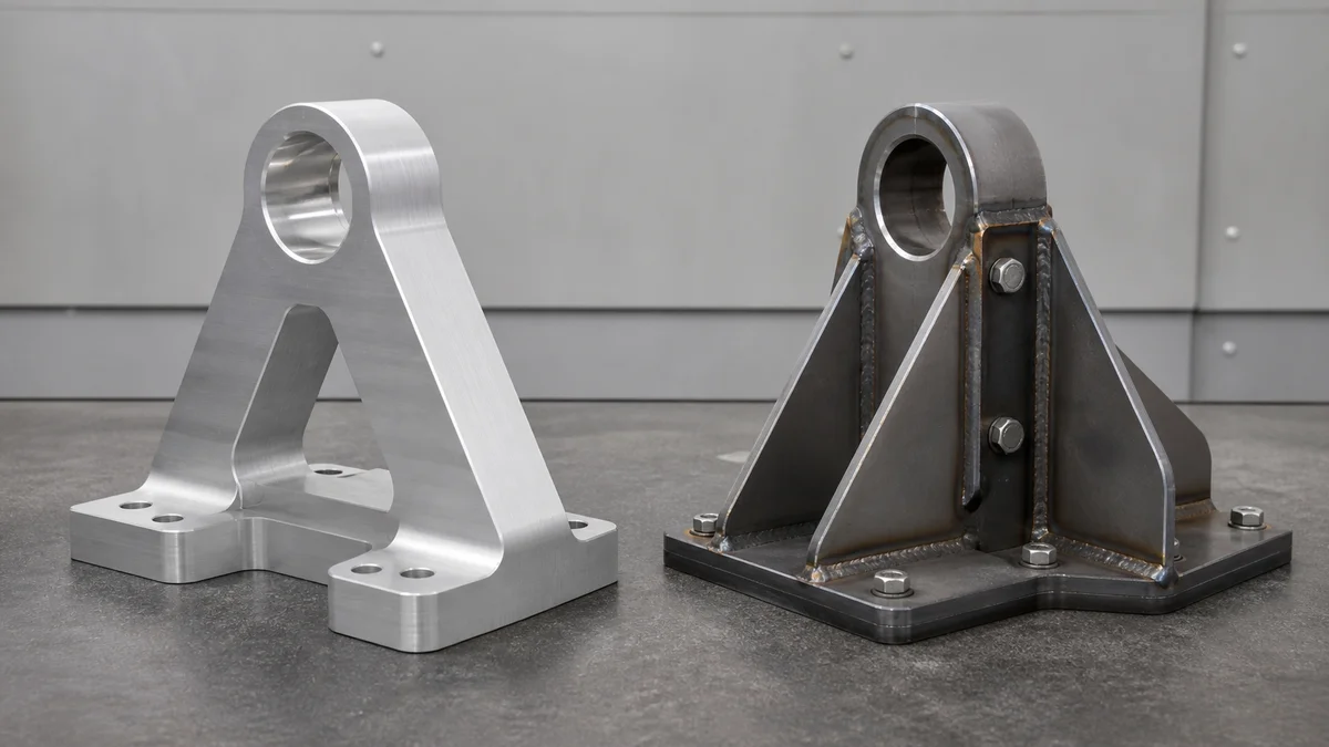
One-piece construction can eliminate welds, fasteners, inserted hardware, and inter-part alignment steps. It may also let critical bores, faces, and mounting features share a coherent datum structure. The tradeoff is a larger stock envelope, greater material removal, more machining setups, or difficult internal access.
A fabricated assembly divides the design into flat blanks and bent components. This can reduce solid-stock use and mass, but it introduces joint design, bend variation, hardware installation, weld effects, finishing access, and final assembly inspection.
| Decision factor | One-piece CNC machining | Fabricated assembly |
|---|---|---|
| Material strategy | Solid stock with material removed | Sheet blanks shaped and joined |
| Interfaces | Fewer inter-part interfaces | More joints, fasteners, or welds |
| Datum control | Related features can share datums | Relationships cross component boundaries |
| Weight strategy | May retain more material | Supports open, thin-wall construction |
| Revision impact | Programming, stock, or fixture changes | Blank, bend, joint, or hardware changes |
| Acceptance state | Machined component | Components plus completed assembly |
Scenario: A rigid equipment support can be machined as one block or fabricated from bent plates with a welded reinforcement. This process-selection scenario is not a customer case. Machining may simplify locating features; fabrication may reduce material use. Required stiffness, allowable joints, final weight, critical interfaces, cosmetic expectations, quantity, and inspection scope determine the better route.
Tolerance stack-up is the accumulated effect of variation across multiple components and operations. Consolidation can reduce that stack, but only if the resulting one-piece geometry remains accessible and inspectable.
Define whether the quotation covers loose components, a fastened assembly, a welded assembly, or a fully finished and inspected unit. Otherwise, suppliers may price materially different deliverables.
How Do Quantity and Revision Risk Affect Process Cost?
Quantity changes how programming, setup, forming tools, fixtures, and inspection effort are distributed, but no universal crossover determines the cheaper process. CNC machining may suit changing designs or lower-volume precision work, while stable sheet designs may benefit from efficient material use and repeat fabrication.
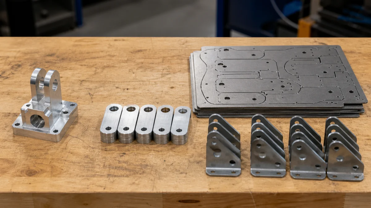
Evaluate cost against the project stage. A prototype intended for fit checks may use flexible programming and simple workholding. Stable repeat production may justify developed fixtures, forming tools, batch planning, or a more formal inspection routine even when the part geometry stays unchanged.
CNC machining avoids dedicated forming dies, although it still requires programming, workholding, setup, and tool planning. A revision may change toolpaths, stock selection, or fixtures. That flexibility can be valuable while precision interfaces are moving or demand remains uncertain.
Sheet fabrication may use material efficiently because blanks can be arranged within the available sheet. Its complete cost can still include programming, cutting, bend setup, forming tools, hardware, welding, deburring, finishing, inspection, and assembly. Dedicated tooling risk6 becomes more important when the design needs specialized formed features or may transition to metal stamping.
Request quantity tiers that correspond to actual decisions:
- Immediate prototype or validation quantity.
- Pilot quantity for assembly and process review.
- Expected repeat lot size.
- Projected annual demand, if known.
- Design-freeze or expected-revision status.
- Partial-delivery requirements.
Ordering extra parts solely to reduce unit price can create obsolete inventory when revisions remain likely. Conversely, repeatedly buying a stable fabricated assembly as isolated one-off work may prevent suppliers from proposing better workholding, tooling, nesting, or batch strategies.
Compare material utilization, setup count, forming-tool exposure, joining, finishing, inspection, documentation, and delivery assumptions at every requested tier. The useful question is not which process is always cheaper, but which cost structure matches current production intent and revision risk.
When Does a Hybrid Sheet Metal and CNC Machining Route Make Sense?
A hybrid route makes sense when sheet fabrication can create the main structure efficiently but selected interfaces need precision after forming. Machined holes, sealing faces, pockets, or datum features should be added only where their functional value justifies another setup, operation sequence, and inspection stage.
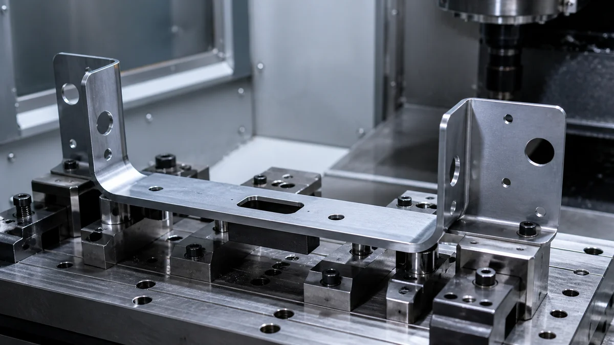
Hybrid manufacturing7 separates structural geometry from local precision. The base component may be cut, bent, formed, or joined before it is located for CNC machining. This preserves uniform-gauge construction while adding control where assembly, sealing, alignment, or motion requires it.
Suitable post-form features may include locating holes, fitted bores, sealing faces, datum pads, and selected pockets. The drawing should distinguish features created in the flat blank, features produced by forming, and surfaces finished afterward.
Which operation should establish the final datum?
The datum should represent the functional interface and remain accessible after forming. Referencing an unstable or non-functional formed edge can produce a precise machined feature that is poorly related to the actual assembly. Define functional surfaces or datum targets clearly enough for both fixture and inspection planning.
Example: A bent mounting frame needs two holes to align with a precision mating component. Cutting those holes before bending leaves their final relationship dependent on bend variation and springback. Machining after forming may protect alignment if the frame can be located and supported consistently. This is a teaching example, not a capability claim.
The RFQ should identify:
- The required operation sequence or final characteristics.
- Post-form datums and critical tolerances.
- Surfaces machined after bending or welding.
- Whether dimensions apply before or after finishing.
- Finish buildup on fitted or sealing interfaces.
- Final inspection and reporting requirements.
Ask suppliers to compare the hybrid route with fully machined and fully fabricated alternatives. Secondary machining is valuable when it solves a defined interface problem; it should not be used to compensate for ambiguous bend, weld, finish, or assembly requirements.
Why Is Unit Price Alone an Incomplete Comparison?
Unit price is incomplete when quotations cover different material, assembly, finishing, inspection, or delivery states. Compare equivalent finished configurations and the complete manufacturing route, including setup, forming, joining, hardware, secondary machining, surface treatment, documentation, and risk created by multiple operations.
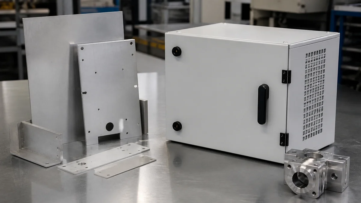
The primary-operation price does not establish total delivered cost. A sheet-cutting quote may exclude bending, hardware, welding, deburring, finishing, assembly, or inspection. A machining quote may exclude requested material documentation, secondary treatment, reporting, or assembly hardware. Neither offer is comparable until scope is aligned.
Use one quotation basis for every process option:
- Exact material grade, condition, stock form, and sheet gauge where applicable.
- Immediate quantity and prototype, pilot, or production intent.
- Programming, fixtures, setups, forming tools, and dedicated tooling assumptions.
- Cutting, machining, bending, welding, fastening, and hardware insertion.
- Deburring, edge treatment, burr direction, and cosmetic requirements.
- Surface finish, coating, masking, and dimensional condition before or after finish.
- Inspection scope, documentation, and final acceptance state.
- Packing, partial delivery, and external process dependencies.
A coating can create finish buildup8 on fitted features, and welding can affect final geometry. These are not optional details when dimensions or assembly interfaces are evaluated after processing.
Example: One quotation covers loose unfinished enclosure panels; another covers a welded, coated, hardware-installed, and inspected assembly. The lower unit price does not identify the better offer because the deliverables differ. This is a quotation-review example, not a customer case.
Risk also has structure. A machined part concentrates stock and machining effort in one component. A fabricated assembly distributes work across several blanks but adds interfaces and process handoffs. Resolve price gaps by checking geometry, material, tolerances, finish, quantity, inspection, assembly state, revision, and delivery assumptions—not by treating price alone as evidence of quality.
What Should a Process-Neutral RFQ Include?
A process-neutral RFQ should define the required final part without forcing an unsupported manufacturing route. Provide controlled geometry, material, quantity, functional tolerances, finish, inspection, revision, assembly state, and delivery expectations, then state whether suppliers may propose machining, fabrication, or a hybrid alternative.
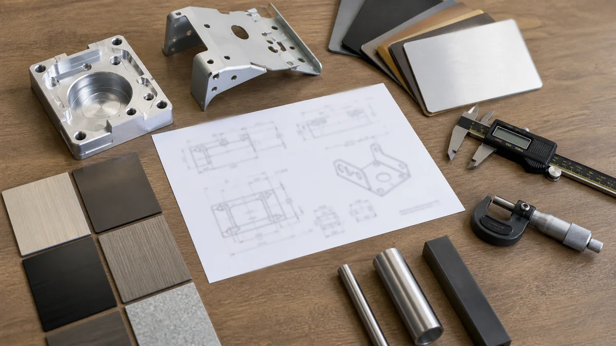
A complete RFQ lets suppliers compare routes against the same acceptance requirements. It also limits assumptions caused by missing geometry, unclear revisions, or undefined inspection scope.
Use this RFQ and approval checklist:
- ☐ Provide the complete 3D model, including hidden geometry and assembly interfaces.
- ☐ Provide the controlled 2D drawing and identify the governing document if files conflict.
- ☐ State the part number and current revision level.
- ☐ Specify the exact material grade and condition.
- ☐ Identify the required stock form or authorize alternatives.
- ☐ For sheet options, state the gauge or permitted gauge range.
- ☐ State quantity, prototype or production intent, repeat demand, and revision stability.
- ☐ Separate functional, assembly-related, cosmetic, and non-critical features.
- ☐ Identify critical tolerances, datums, GD&T, flatness, and assembly relationships.
- ☐ Define bends, formed details, welds, hardware, joints, and required assembly state.
- ☐ Mark surface-finish zones, cosmetic surfaces, masking, coating, and edge requirements.
- ☐ State burr direction where it affects handling, assembly, sealing, or appearance.
- ☐ Clarify whether dimensions apply before or after finishing.
- ☐ Define inspection expectations, sampling, first-article needs, and required reports.
- ☐ State delivery expectations and whether partial shipments are acceptable.
- ☐ Authorize or prohibit machining, fabrication, or hybrid alternatives explicitly.
Do not request “CNC turret punching, CNC punch press, CNC-controlled stamping equipment, or metal stamping depending on the actual process” without clarification. State CNC turret punching, CNC punch press work, CNC-controlled stamping equipment, or metal stamping as appropriate. Plastic injection molding should appear only as a separate polymer process if it is genuinely an allowed alternative.
Before approval, compare each offer against the same manufacturing RFQ package9 and record supplier exceptions. A process recommendation is meaningful only when every route is evaluated against one controlled final requirement.
For a clear process recommendation or quotation, send the 3D model, controlled 2D drawing, material grade, quantity, prototype or production intent, critical tolerances, surface finish, inspection expectations, revision level, required assembly state, and delivery expectations.
References
-
Sheet Metal Fabrication vs. CNC Machining - CNC machining involves manufacturing parts out of metal. Sheet metal forming involves the various manufacturing processes used to manipulate ... ↩
-
A Conceptual Data Model of Datum Systems - by MR McCaleb · 1999 · Cited by 19 — The technical drawing presented in Fig. 3 shows a datum plane that is established from two datum features (datum features A and B). ↩
-
Sheet Metal Design for Manufacturability - A +/- 1 degree tolerance on all bend angles is generally acceptable in the industry. Flange length must be at least 4 times the material thickness. ↩
-
Understanding ASME Y14.5.1: Mathematical Definitions of ... - These relate features to datums, such as parallelism, perpendicularity, and angularity. Mathematically, Y14.5.1 defines them as zones parallel ... ↩
-
What is AS9102 First Article Inspection? - In the AS&D industry, when a new or revised part is produced for the first time, it must be verified to ensure all requirements have been met. ↩
-
Advanced Metal Stamping Tool Design - This concept is ideal for projects with forecasted lower volume production, enabling clients to invest in tooling that aligns with their specific demands ... ↩
-
CNC Machining vs Sheet Metal Fabrication - PCB Manufacturer - Hybrid approaches are common and often optimal: a sheet metal base with critical precision features added by secondary CNC machining, or a CNC ... ↩
-
Chapter 8: Practical Design Guidelines for Surface Engineering - The thickness of a surface coating or case depth is governed by both the process characteristics and the cost. For example, in theory it would be possible to ... ↩
-
RFQ Checklist: What to Include for Faster Quotes - A manufacturing RFQ includes the 3D model, 2D drawing, material specification, quantity, lead time, tolerance requirements, surface finish, and inspection level ... ↩