
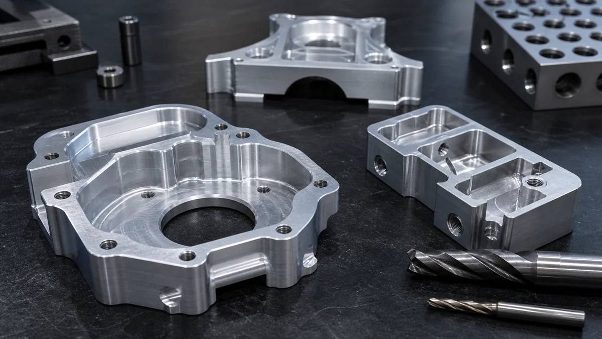
Undercuts and internal corners may look simple in a 3D model, yet they directly affect cutter access, tool rigidity, setup planning, inspection, cost, and lead time. A rotating milling cutter naturally leaves an internal radius. An undercut blocks a normal straight approach and may require a lollipop, T-slot, or dovetail cutter.
Good design begins with function. Retain difficult geometry only when it supports fit, sealing, retention, clearance, or assembly. Then coordinate its dimensions with material grade, pocket proportions, tolerance, surface finish, inspection method, quantity, and production intent.
The decisions below separate necessary features from avoidable machining constraints and show what a supplier needs to evaluate the part without adding conservative assumptions.
When Should You Keep or Remove an Undercut?
Keep an undercut only when it provides necessary retention, clearance, sealing, or assembly function. If an accessible recess, revised mating component, or split-part construction can achieve the same result, removing the undercut will usually simplify tooling, setups, inspection, and quotation.
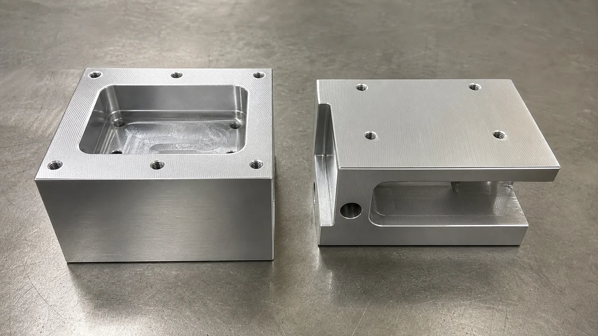
An open pocket can be approached directly with a standard end mill. An undercut leaves material above or beside the cutting area, blocking that straight approach. Reaching behind the obstruction may require a lollipop, T-slot, or dovetail cutter.
Classify the feature before approving it:
- Functional: It retains a seal, captures a component, provides necessary clearance, or creates a required mating profile.
- Assembly-related: It permits installation or movement that cannot occur through an open direction.
- Non-critical: It remains because of modeling convenience, appearance, or an inherited design with no confirmed purpose.
Even a functional undercut is not automatically the best solution. Compare it with an open-sided recess, through-slot, removable insert, or split assembly. Splitting the part may add fasteners and tolerance stack-up—the accumulated dimensional variation between assembled components—but can improve machining and inspection access. Material grade, quantity, revision stability, finish, and critical feature relationships should guide the choice.
Example: A molded housing concept is converted into a machined prototype without removing a side-action undercut. Plastic injection molding uses mold parting, draft, gate location, and sometimes side actions; CNC machining removes material with cutting tools. A feature justified by mold operation may have no useful role in the machined version.
For an early prototype, simpler geometry usually preserves more revision flexibility. For stable production geometry, an undercut can remain when its function is documented and both the cutting path and inspection method are practical. This undercut design review1 should happen before the drawing is released for quotation.
How Much Clearance Does an Undercut Tool Need?
Provide clearance for the complete cutter, shank, holder, entry motion, cutting path, and withdrawal—not just the finished undercut. Clearance of at least four times the undercut depth is a useful review reference, but actual feasibility depends on geometry, tooling, material, fixtures, and machine access.
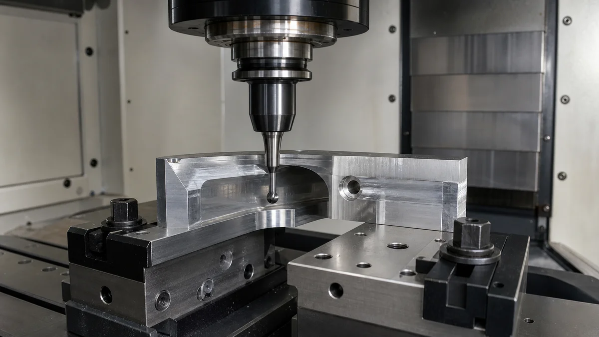
Evaluate undercut access as a motion envelope. The cutter must enter the cavity, move behind the obstructing wall, generate the profile, and withdraw without striking adjacent geometry or workholding. The shank and holder may require substantially more space than the cutting head.
Clearance equal to at least four times the undercut depth is a useful DFM reference for identifying restricted internal geometry. It is not a universal capability limit. The actual undercut clearance requirement2 depends on cutter diameter, neck and shank proportions, tool reach, access angle, material behavior, fixture position, and whether the part must be indexed or reclamped.
Scenario: A housing contains a circumferential recess behind a narrow opening. The recess appears compatible with a small lollipop cutter, but a nearby wall blocks lateral entry. Increasing the recess diameter does not solve the access problem. Widening the opening, moving the wall, changing the approach direction, or splitting the housing may work better. This is a teaching scenario, not a customer case.
Restricted access has predictable consequences. It may force a smaller cutter, increase tool overhang, reduce rigidity, and raise exposure to chatter or deflection. Another orientation may be required, adding setup and datum-transfer considerations. The fixture must also stay outside the entry and withdrawal path, while the finished feature must remain accessible for inspection.
Show the approach direction in the 3D model and add a section or detail view to the drawing. If surrounding geometry may change, identify the permitted adjustment range. That freedom helps the supplier choose the simplest viable access strategy instead of pricing around an assumed collision risk.
How Deep Should a CNC Machined Undercut Be?
Keep undercuts shallow relative to cutter or blade diameter whenever function allows. Features below about two times tool diameter favor more rigid access, three to four times diameter warrant careful review, and depths beyond six times diameter should trigger direct supplier evaluation rather than automatic approval.
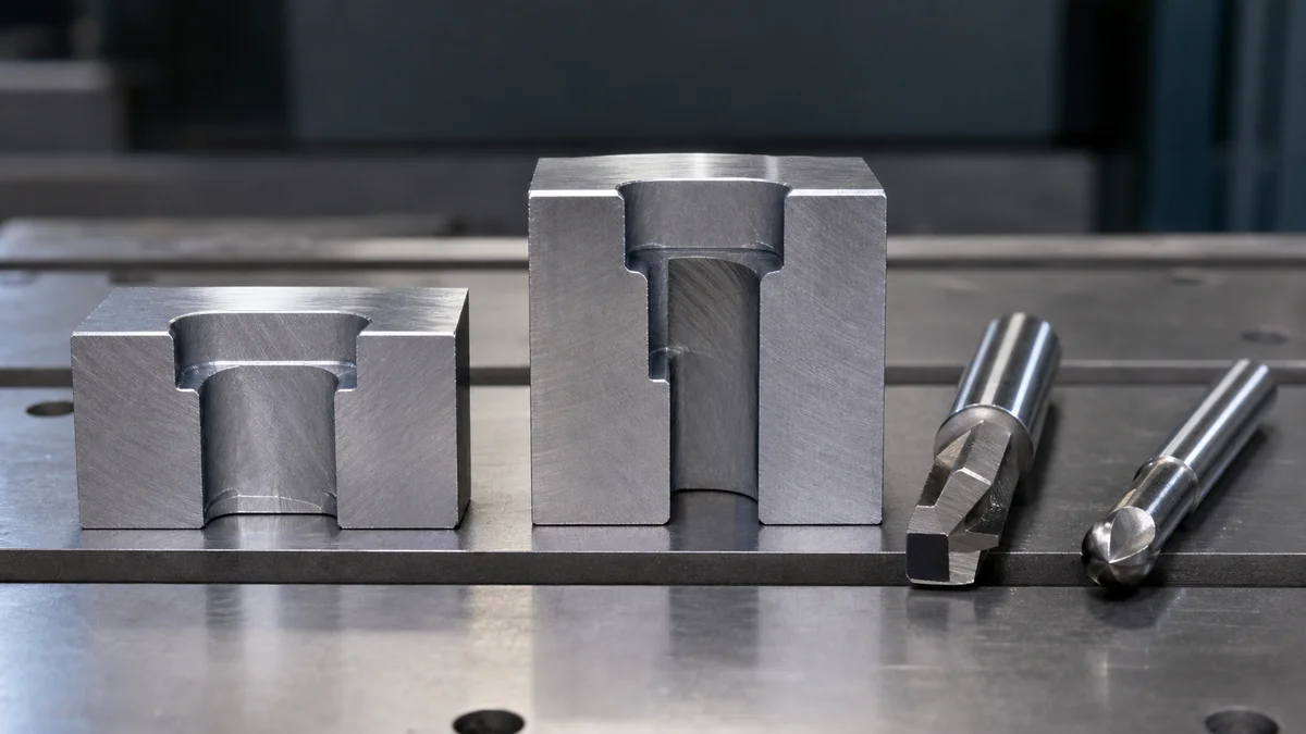
Undercut depth determines how far the cutting element must reach behind a wall or into a restricted area. As reach grows, the tool becomes more sensitive to deflection and vibration. Protecting dimensions and surface finish may then require lighter passes, adjusted cutting conditions, specialized tooling, or another setup.
The supported depth-to-tool-diameter guidance is best used as a review framework:
| Undercut depth relative to relevant tool diameter | Tooling concern | Drawing or RFQ action |
|---|---|---|
| Below about 2×D | More favorable for rigid access | Confirm profile, entry path, and required finish |
| About 3–4×D | Reach and cutter form need review | Ask the supplier to assess material, neck clearance, and setup |
| Above about 6×D | Deflection and access risk become more significant | Evaluate less depth, more diameter, wider entry, or redesign |
These ranges are DFM signals, not guaranteed process limits. The diameter must refer to the relevant cutter or blade geometry, not an unrelated pocket dimension. A T-slot cutter includes a head, neck, and shank; each can become the limiting feature.
If the functional depth cannot decrease, check whether cutter diameter can increase, the opening can widen, or another orientation can provide shorter reach. Material grade matters because tool wear and cutting behavior can make the same geometry more demanding in one material than another.
Avoid combining a deep undercut with blanket close tolerances and fine surface finish unless each requirement protects a defined function. Depth, restricted access, finish, and extensive inspection can make one feature dominate the manufacturing plan. A clear undercut depth ratio3 gives the supplier a better starting point for that review.
What Internal Corner Radius Should You Specify?
Specify the largest internal corner radius that preserves fit and clearance, and keep it larger than the intended cutter radius. The research supports practical references from about 0.3 mm to 0.5–0.8 mm, but cutter size, pocket depth, material, finish, and supplier capability remain controlling factors.
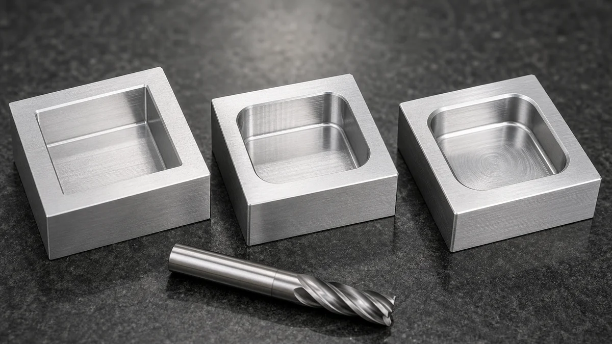
A rotating milling cutter cannot directly produce a perfectly sharp internal corner. Its circular geometry leaves a radius where pocket walls meet. Reducing that radius normally requires a smaller cutter, which is usually less rigid than a larger tool when reach and cutting conditions are comparable.
The supported guidance recommends making the specified part radius larger than the cutter radius. About 110% of tool radius is presented as a minimum review reference, while roughly 130% is cited as a common target. The additional space lets the cutter follow a smoother path instead of becoming heavily engaged or rubbing in the corner.
| Specified corner condition | Practical tooling consequence | Specification response |
|---|---|---|
| Sharp internal corner | Not a normal direct milling result | Define its function and evaluate a secondary process or relief |
| Very small radius | May force a small cutter with reduced rigidity | Localize the requirement to the mating area |
| Radius slightly larger than cutter radius | Provides room for cutter movement | Confirm the intended radius relationship during DFM review |
| Largest radius allowed by fit | Supports larger, stiffer tooling | Use as the preferred default |
The references from about 0.3 mm to 0.5–0.8 mm are starting points, not universal minimums. A shallow aluminum pocket and a deep pocket in a more demanding material do not present equal risk merely because their radii match.
Place vertical corner radii on the controlled drawing and use detail views when the model could be misread. State whether the value is mandatory or whether the supplier may increase it. Clear internal corner radius guidance4 prevents a nominal CAD detail from being priced as a precision-critical feature.
How Should Corner Radius Change with Pocket Depth?
Increase internal corner radii as pocket depth and tool reach grow, while also reviewing pocket width and opening clearance. A generous radius cannot fully correct a deep, narrow cavity that still forces a long, slender cutter or blocks the tool holder.
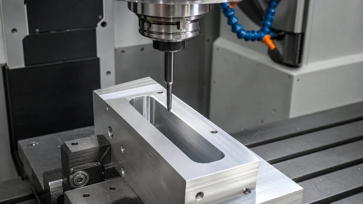
Corner radius, pocket depth, width, and opening size form one tooling decision. A larger radius may allow a larger cutter, but that benefit disappears when the cavity still requires excessive reach. Long tools are more sensitive to chatter and deflection, while deep narrow pockets can also restrict chip evacuation.
Cavity depth around four times cavity width is a practical review reference. It should trigger discussion, not serve as a universal rejection limit. Material grade, wall thickness, workholding, local tolerance, surface finish, and the available approach direction all influence feasibility.
Scenario: A rectangular pocket is wide enough for a larger cutter, but a hidden shoulder near the opening blocks the holder before the tool reaches the bottom. Enlarging only the lower corner radius does not solve the problem. The designer could shorten the pocket, remove the shoulder, widen the upper opening, or permit another machining orientation. This is a teaching scenario.
Diagnose the geometry in this order:
- Increase the radius while preserving assembly clearance.
- Widen the pocket and its entry opening where possible.
- Reduce depth or divide the cavity into accessible levels.
- Align major walls with a principal machining direction.
- Remove shoulders that obstruct the shank or holder.
- Check whether indexed or 5-axis access offers a real advantage.
Do not prescribe 5-axis machining simply because a pocket looks complex. A direct 3-axis approach may remain appropriate when all critical surfaces are accessible. Multi-axis machining becomes relevant when tilting or indexing creates shorter, clearer access. The final pocket depth and width decision5 should follow the actual cutter and holder path, not the pocket outline alone.
What Should You Specify When a Sharp Internal Corner Is Essential?
Treat a sharp internal corner as a nonstandard requirement and identify exactly where and why it is needed. Standard CNC milling leaves a cutter radius, so the supplier may need EDM, a secondary finishing operation, alternate mating geometry, or a split assembly.
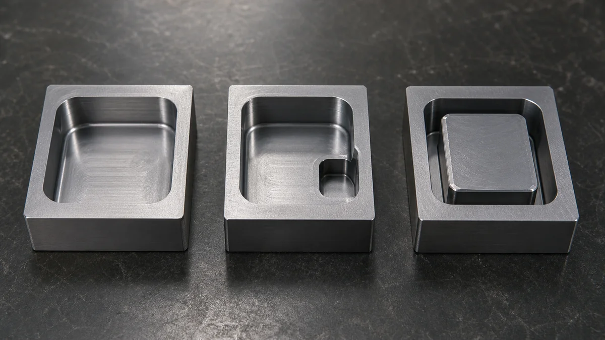
The word “sharp” is not a complete specification. It could mean no visible radius, minimal residual material, clearance for a square mating component, or a local condition needed for sealing or retention. Each interpretation can lead to a different process and inspection plan.
Define the functional condition before selecting a process:
- Which corner, edge, or depth range is affected?
- What mating feature creates the requirement?
- What maximum radius can the assembly accept?
- Would a dog-bone relief, local clearance, or mating-part chamfer work?
- Must the condition continue through the full pocket depth?
- What inspection method will establish acceptance?
EDM may be considered when a rotating cutter cannot produce the required geometry, but it should not be prescribed automatically. Depending on material, depth, access, tolerance, surface condition, quantity, and production intent, a supplier may recommend secondary finishing, a revised pocket, a modified mating component, or a split assembly.
Example: A square insert seats against two pocket walls, but only its outer tip conflicts with the milled radius. Requiring all four corners to be perfectly sharp adds work that does not protect the fit. A localized relief or small chamfer on the insert may resolve the interference. This is a teaching example, not a customer case.
A blanket “SHARP CORNERS” note creates no measurable acceptance criterion. One supplier may assume a normal cutter radius; another may include secondary processing. Replace it with a dimensioned local requirement, identify acceptable alternatives, and describe the functional sharp corner requirement6 in terms the machinist and inspector can verify.
How Should You Tolerance and Inspect Hidden Undercuts?
Tolerance only the hidden undercut dimensions and relationships that control fit, sealing, retention, or alignment, then select an inspection method that can physically reach them. Define functional datums, measurement conditions, inspection frequency, and required reporting before quotation so acceptance is both practical and unambiguous.
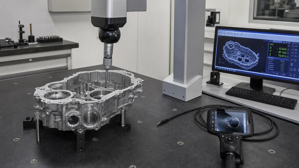
A hidden undercut can carry separate requirements for profile width, depth, diameter, angle, corner radius, datum location, and surface finish. Do not tighten every characteristic equally. Identify what controls function, then leave clearance and cosmetic geometry under a suitable general tolerance where possible.
Use GD&T when a relationship matters more than feature size alone. Profile or position relative to a functional datum may express retention or alignment more clearly than several chained dimensions. Chained dimensions create tolerance stack-up, while a functional datum provides a common origin. The datum must remain accessible and repeatable during machining and measurement.
| Characteristic to verify | Possible inspection method | Information the drawing must provide |
|---|---|---|
| Accessible width or depth | Caliper, micrometer, or suitable depth measurement | Contact surfaces and required measurement direction |
| Hidden profile or datum location | CMM or optical method where access permits | Datum scheme, tolerance zone, and critical surface |
| Internal visual condition | Borescope where appropriate | Defined visual acceptance condition |
| Repeated functional fit | Purpose-designed gauge where justified | The mating or retention condition represented by the gauge |
These are possible methods, not mandatory equipment requirements. The supplier should propose an approach suited to the geometry, tolerance, quantity, and reporting scope.
Common specification mistake: A close tolerance is applied to a hidden recess without a datum, probe path, or inspection frequency. The supplier must estimate both manufacturing and acceptance risk. State whether verification applies to the first article, a production sample, every part, or a final report. If anodizing, plating, or another treatment reaches the undercut, specify whether dimensions apply before or after finish buildup. A workable hidden feature inspection plan7 must account for that final dimensional condition.
What Should an Undercut and Internal-Corner RFQ Include?
Submit both the 3D model and controlled 2D drawing, define every access-critical feature, and state which design alternatives are acceptable. Add material, quantity, production intent, tolerances, finish, inspection, revision, and delivery requirements so the supplier can quote tooling, setups, verification, and schedule coherently.
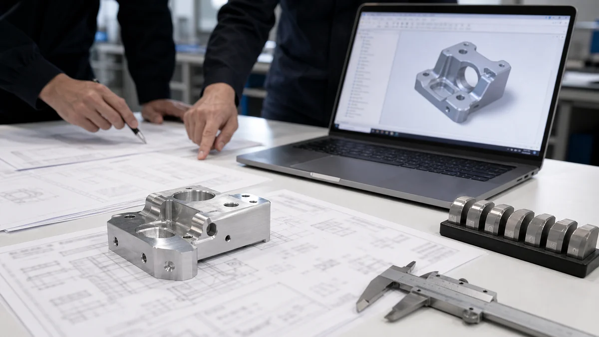
The 3D model communicates complete geometry and supports tool-motion review. The controlled 2D drawing defines requirements the model may not convey reliably: tolerances, datums, surface finish, units, inspection notes, and revision. Section and detail views should expose hidden profiles and access directions.
Use this CNC machining RFQ checklist8:
- ☐ Current 3D CAD model and controlled 2D drawing
- ☐ Active part number, units, and revision level
- ☐ Exact material grade and condition or temper
- ☐ Undercut profile, depth, width, angle, and access direction
- ☐ Internal corner radii and any acceptable radius range
- ☐ Pocket depth, width, entry opening, and hidden shoulders
- ☐ Functional, assembly-related, cosmetic, and non-critical features
- ☐ Critical tolerances, functional datums, and focused GD&T
- ☐ Surface finish localized to the surfaces that require it
- ☐ Deburring, coating, masking, and secondary operations
- ☐ Whether dimensions apply before or after finish buildup
- ☐ Inspection intent, method, frequency, and reporting scope
- ☐ Quantity and prototype, pilot, or production intent
- ☐ Expected revisions or annual usage when known
- ☐ Delivery expectations and partial-shipment requirements
- ☐ Permission to propose larger radii, shallower undercuts, other setups, or split construction
- ☐ Controlling document identified if model and drawing conflict
Confirm the process name. CNC machining removes material from solid stock. CNC turret punching and CNC punch press work use programmed punches on sheet. Metal stamping uses dedicated dies and must address matters such as burr direction and springback. Sheet metal fabrication may combine cutting, punching, bending, welding, and finishing. Plastic injection molding forms polymers in a mold and introduces different considerations, including draft and gate location.
“CNC turret punching, CNC punch press, CNC-controlled stamping equipment, or metal stamping depending on the actual process” is not one standard process term. Specify whether the request concerns turret punching, a CNC-controlled stamping machine, general die stamping, or another process. This process terminology clarification9 prevents incompatible tooling and geometry assumptions.
For a manufacturability recommendation or quotation, send the 3D model, controlled 2D drawing, material grade, quantity, prototype or production intent, critical tolerances, surface finish, inspection expectations, revision level, delivery requirements, and any undercut dimensions or corner radii that cannot change.
References
-
Undercuts in Machined Parts: Design Tips - American Micro Industries - Learn about undercuts in machined parts! This guide covers design considerations, machining techniques, and when undercuts are necessary. ↩
-
Tips For CNC Machined Parts With Undercuts Machining - SANS - Keeping the main width four times the undercut depth will help ensure that the knife has enough clearance to work properly. ↩
-
CNC: How to design quality parts for CNC machining (tips & tricks) - Cavity depths should not exceed 3 to 4 times their diameter. Ten times the tool diameter, or 25 cm, is advisable. Tool deflection, chip evacuation, and ... ↩
-
Milling inside corners - Sandvik Coromant - Alternatively, use a smaller DC cutter to mill the desired corner radius. Mill a larger component radius, Corner radius = 75% x DC. Use a smaller cutter, ↩
-
How to design parts for CNC machining | Protolabs Network - Recommended cavity depth: 4 times cavity width. Limiting the depth of the cavity to four times its width ensures good results. If larger depths parts with a ... ↩
-
Essential Strategies in CNC Machining Sharp Inside Corners - For extremely sharp corners, you can use a small fillet with an internal corner radius of 0.2mm to reduce the stress during machining. Specify a ... ↩
-
Metrology Services | CMM Inspection & First Article Inspection - Our metrology services can help your team with everything from CMM inspection, 3D laser scanning, reverse engineering service, and more. ↩
-
CNC Machining RFQ Template Guide - uneed - The package typically starts with a 3D CAD model, often a STEP file, and a 2D PDF drawing that defines tolerances, GD&T, notes, surface finish, and material ... ↩
-
Differences Between Metal Punching and Stamping - RapidDirect - Metal stamping Vs punching, stamping fabricates complex sheet metal parts, but punching is only for holes Learn their key differences. ↩