
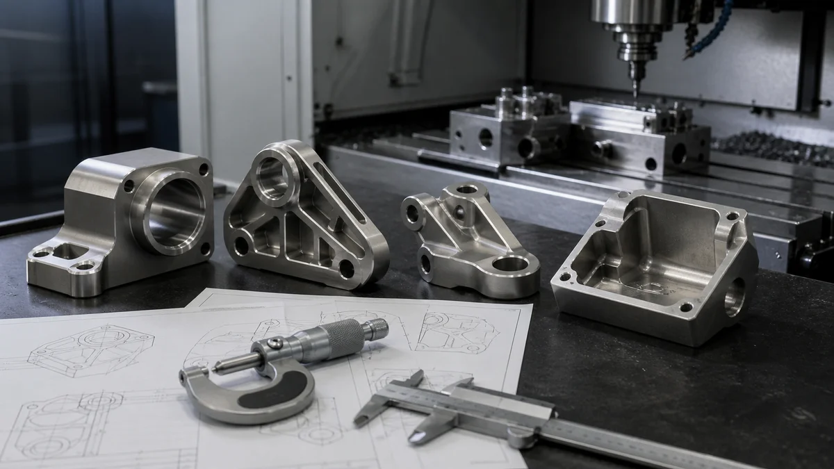
Titanium can be a practical choice when strength, corrosion behavior, weight, or service conditions justify it. Yet material selection alone does not make a titanium part economical. Internal radii, pocket depth, wall stiffness, cutter access, setup count, tolerances, surface finish, stock form, and inspection scope all shape the manufacturing plan.
Cost-effective design protects the features that make the part work while relaxing details that add cutting, tooling, fixturing, or inspection effort without improving performance. Engineering and procurement teams therefore need to show what is critical, what may change, and where suppliers may propose alternatives.
The following decisions provide a structured way to review a titanium design before quotation, compare manufacturing routes consistently, and prepare an RFQ that supports useful DFM feedback.
Is CNC Machining the Right Process for the Titanium Part?
Choose CNC machining when the part must be produced by removing material from solid titanium stock and its geometry, quantity, tolerances, or production stage support that route. Confirm the process name before quotation because machining, punching, stamping, sheet fabrication, and molding involve different materials, tooling, and design constraints.
CNC machining covers subtractive operations1 such as milling, turning, drilling, boring, and reaming. It can suit titanium prototypes, changing designs, precision interfaces, and production parts, but the route should follow the actual geometry and production intent rather than a habitual process label.
| Process | Starting material and operating principle | Typical design basis |
|---|---|---|
| CNC machining | Removes material from solid stock | Three-dimensional parts, pockets, bores, turned profiles, and precision relationships |
| CNC turret punching | Uses programmed punch tools on sheet metal | Sheet holes, cutouts, and supported formed features |
| Metal stamping | Cuts or forms sheet with dedicated dies | Stable sheet geometry and production demand that can justify tooling |
| Sheet metal fabrication | Combines cutting, punching, bending, welding, and finishing | Parts based on substantially uniform sheet thickness |
| Plastic injection molding | Forms molten polymer inside a mold | Moldable polymer geometry and dedicated production tooling |
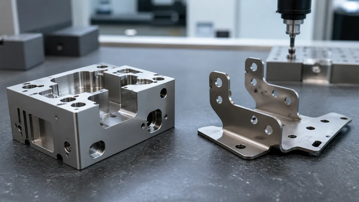
“CNC turret punching, CNC punch press, CNC-controlled stamping equipment, or metal stamping depending on the actual process” is not one standard process term. It might be intended to mean CNC turret punching, CNC punch press work, CNC-controlled stamping equipment, or general die stamping. Replace it in the RFQ with the exact operation so suppliers do not price different manufacturing routes.
Example: A solid titanium housing with pockets, threaded holes, and a controlled sealing face is fundamentally different from a titanium sheet bracket with punched holes and bends. Describing both as “CNC work” hides the stock form, tooling, dimensional relationships, and inspection assumptions needed for comparable quotations.
Process selection should also reflect quantity and design maturity. Machining may limit dedicated-tooling exposure while revisions remain likely, but that does not make it the lowest-cost route for every stable geometry or production program.
Which Titanium Grade Meets the Requirement Without Adding Unnecessary Machining Cost?
Specify the least demanding titanium grade and condition that satisfies the documented load, corrosion environment, service conditions, and production requirements. A higher-strength grade should solve a defined engineering need because grade selection influences stock availability, cutting behavior, tool wear, material verification, and the complete delivered-part quotation.
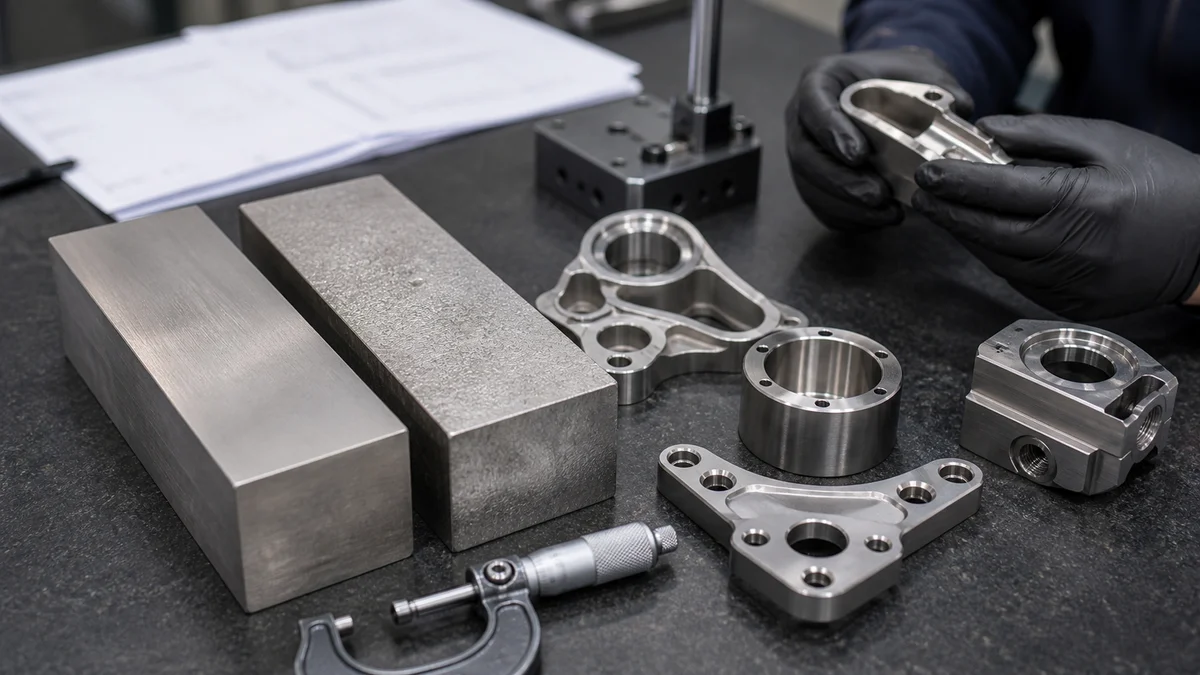
Begin with the operating requirement that makes titanium necessary. Strength, corrosion behavior, temperature, weight, joining, and required documentation may all influence the selection. Titanium grades are not steps on a general quality ladder.
| Selection factor | Commercially pure Grade 22 | Ti-6Al-4V Grade 5 |
|---|---|---|
| Conditional fit | Function does not require the higher-strength alloy | Documented loading or strength-to-weight needs justify it |
| Machining consideration | May be easier to machine when suitable for the application | May create greater cutting and tool-wear demands |
| Drawing callout | Exact grade, condition, and applicable product form | Exact grade, condition, and applicable product form |
| RFQ evidence | Service environment and required material records | Load requirement, service environment, and required material records |
| Specification risk | Selection without confirming mechanical requirements | Default selection without showing why the additional strength is needed |
Grade selection and tolerance capability are separate decisions. Specifying Grade 5 does not automatically produce a more accurate bore, surface, or hole pattern. Geometry, workholding, tool access, setup relationships, surface finish, quantity, and inspection method still determine manufacturing difficulty.
The drawing should name the exact titanium grade and condition. The RFQ should state whether substitutions are prohibited or may be submitted for engineering approval. If material documentation, source restrictions, or heat-number traceability are required, request them before quotation. Dimensional inspection cannot verify that the specified alloy was used, and traceability effort should not be presumed to accompany every order.
When either grade could satisfy the design, invite suppliers to state their stock, machining, and documentation assumptions. Compare the complete delivered-part route instead of considering raw material alone.
How Should Internal Corner Radii Be Designed for Titanium Milling?
Use the largest internal corner radii that preserve mating clearance and functional geometry, and standardize repeated radii where practical. Larger radii allow the supplier to consider larger, more rigid cutters, while small or near-sharp corners can increase chatter risk, tool changes, finishing passes, tool wear, and machining time.
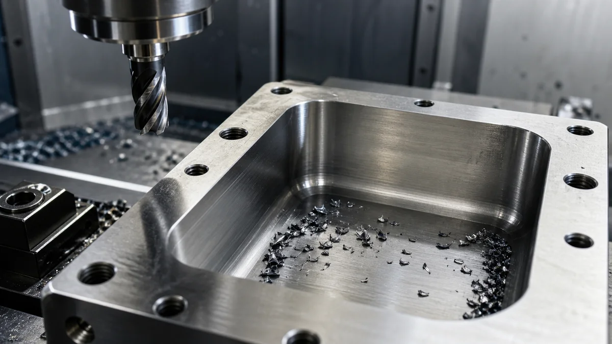
A rotating milling cutter naturally leaves a radius in an internal corner. Ordinary milling cannot directly produce a perfectly sharp internal corner, so modeling one without explaining its function creates uncertainty. The supplier may assume a fillet is acceptable, select a small cutter, or include a separate finishing operation.
Review each corner with practical questions:
- Does a mating component genuinely need to occupy the corner?
- Could that component receive a chamfer or relief instead?
- Can one common radius be reused across several pockets?
- Does the selected radius permit a practical cutter path at the full pocket depth?
- Does a near-sharp region need a detail view and measurable acceptance condition?
Radius and pocket depth must be reviewed together. A radius that appears generous in plan view may still require a long, slender cutter when the cavity is deep. Opening width, adjacent walls, corner transitions, toolholder clearance, tolerance, and surface finish all affect whether a rigid cutter can reach the feature.
Example: A rectangular pocket has four near-sharp corners, but only one protects assembly clearance. Specifying that corner as an exception and enlarging the other three can preserve the interface without forcing small-tool finishing around the complete pocket.
Treat any published minimum radius as a DFM review reference rather than a universal capability limit. If a corner must be sharp, identify the functional portion and permit the supplier to evaluate relief geometry, another machining operation, or a revised mating feature. Ambiguous sharp corners tend to produce either conservative pricing or conflicting interpretations of the finished part.
How Can Deep Pockets and Restricted Tool Reach Be Reduced?
Reduce deep-pocket cost by shortening the cavity, widening its opening, increasing internal radii, or exposing the feature from a more direct machining direction when function permits. Deep, narrow titanium geometry requires longer tools and can increase deflection, vibration, heat concentration, chip evacuation difficulty, finishing effort, and dimensional risk.
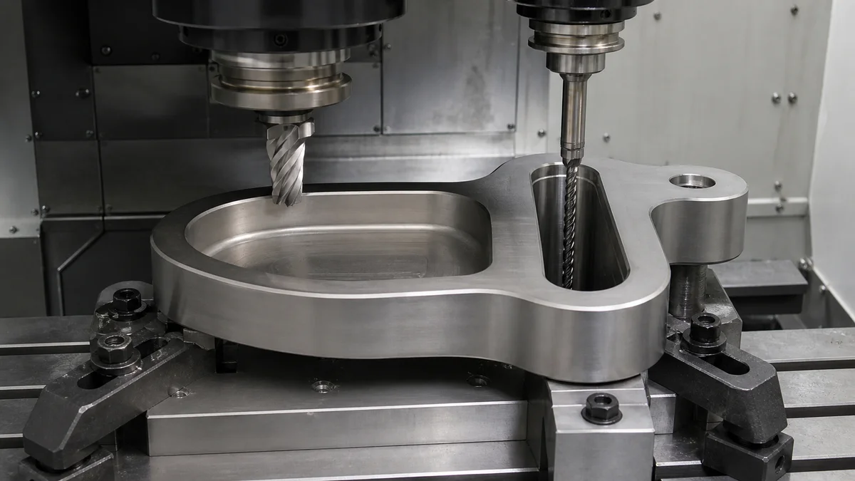
Pocket depth alone does not determine difficulty. The supplier must consider opening width, internal radii, wall height, obstructions, toolholder clearance, required floor and wall conditions, and whether another setup is needed. A broad, open cavity may be less demanding than a shallower feature hidden behind a narrow entry.
Before releasing the design:
- Remove depth that does not support weight reduction, clearance, flow, or assembly.
- Widen narrow entries where adjacent components allow it.
- Replace deep cosmetic recesses with shallower visual features.
- Increase vertical corner radii so a larger, more rigid cutter can enter.
- Consider access from the opposite side when critical datum relationships remain protected.
- Classify pocket floors and walls as functional, clearance, cosmetic, or non-critical.
Should a deep pocket be divided into separate parts?
A split design can provide direct access and shorter tools, but it introduces fastening, alignment, sealing, assembly, and inspection requirements. Compare the delivered assembly rather than assuming division automatically lowers cost. A one-piece design may remain preferable when it removes a critical joint or avoids tolerance stack-up between components.
A common specification mistake is applying the same tight tolerance and fine surface finish to every wall and floor of a deep cavity. If only a mounting ledge or sealing land controls function, localize the requirement there and leave clearance surfaces under general machining requirements.
The drawing should communicate the finished geometry and critical surfaces, not prescribe unsupported feeds, speeds, coolant pressure, or toolpaths. That separation lets the supplier plan tool reach3, chip evacuation, roughing, finishing, and inspection around the actual risk.
How Should Thin Walls and Tall Ribs Be Stabilized During Machining?
Keep titanium walls and ribs thick, short, and supported enough to resist cutting and clamping forces for the actual geometry. Where thin sections are unavoidable, identify their function and measurement condition, provide stable workholding regions, balance material removal, and allow the supplier to review temporary support or revised machining sequences.
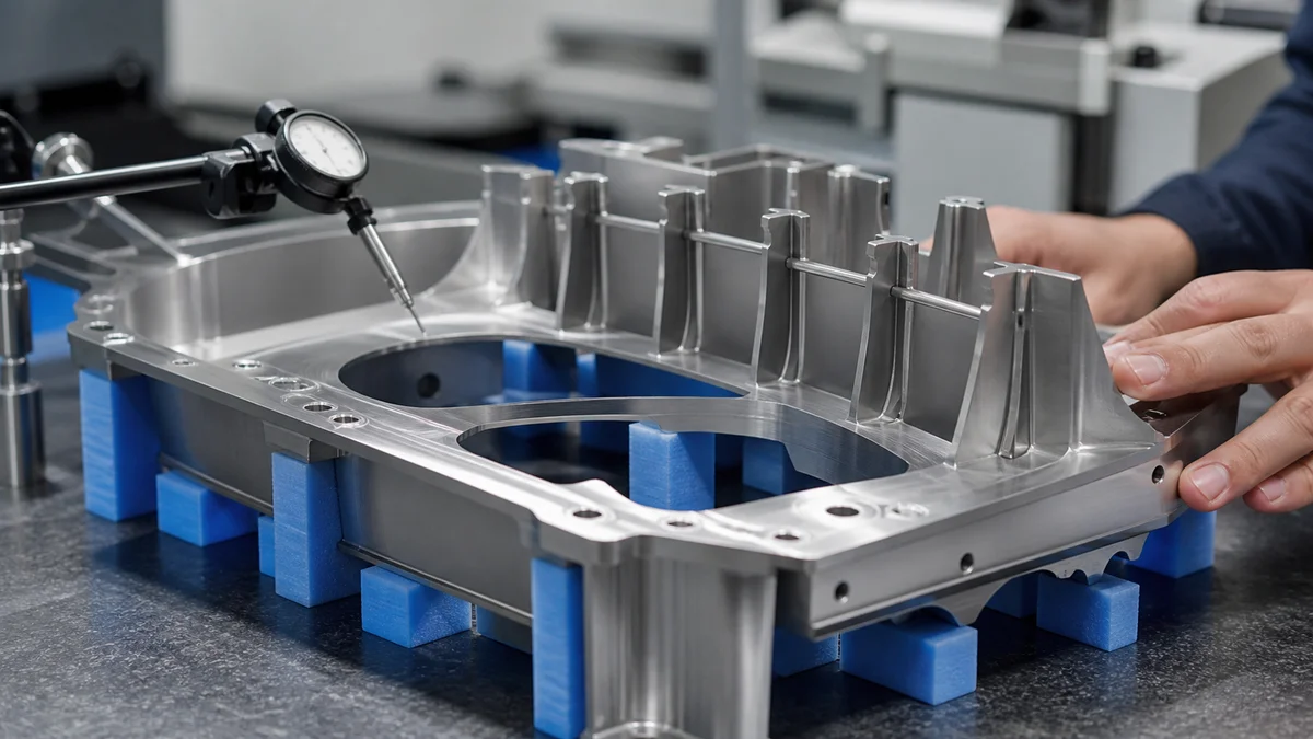
Wall thickness cannot be evaluated independently of wall height, unsupported length, nearby pockets, grade, tolerance, finish, and clamping access. A nominally substantial wall can still behave poorly when it is tall, interrupted, isolated, or surrounded by heavy material removal. Deflection during cutting may create chatter or taper, while clamping may temporarily force a flexible section into a shape that changes after release.
Stability can often be improved by shortening unsupported spans, increasing thickness locally, adding a flange or accessible rib, maintaining more uniform sections, or leaving temporary material through roughing. Temporary bridges and support stock must remain accessible for complete removal, and the model or drawing should distinguish sacrificial material from permanent geometry.
Workholding deserves equal attention. Provide stable regions that may be clamped without marking cosmetic surfaces or deforming delicate features. Instead of prescribing an unsupported fixture design, identify no-clamp zones, functional datums, finished surfaces, and features that must be measured after unclamping.
Scenario: A titanium cover has a broad thin wall surrounding a deep pocket. Tightening the wall-thickness tolerance does not solve the manufacturing risk. A useful review asks whether the pocket can be shallower, whether temporary support can remain during roughing, whether removal can be balanced across the part, and whether final flatness applies in a free or defined restrained condition.
The inspection condition matters because a flexible wall can appear acceptable while held and change when released. State the condition representing delivery or assembly. Quantity and production intent also affect whether flexible workholding or a more developed repeat-production fixture is reasonable.
How Can Setup Count Be Reduced Without Losing Critical Feature Relationships?
Arrange titanium features around the fewest practical machining orientations while identifying the relationships that must remain controlled from common functional datums. Fewer setups can reduce workholding, alignment, datum-transfer, probing, and inspection effort, but additional axis motion is justified only when it improves access or protects a real functional relationship.

A setup begins when the workpiece is located and secured for machining. Repositioning can add fixture preparation, alignment, datum transfer, tool access, and inspection work. Features produced in one clamping are generally easier to relate than features completed after the part is released and located again.
| Strategy | Geometry or relationship it may suit | Approval question |
|---|---|---|
| Conventional 3-axis setup | Accessible faces, pockets, and holes | Can critical features be reached from primary directions? |
| Indexed multi-axis setup | Fixed-angle or multi-face features | Does indexing reduce fixtures and datum transfers? |
| Simultaneous multi-axis machining | Continuously changing cutter orientation | Does the geometry genuinely require continuous movement? |
| Multiple conventional setups | Accessible geometry with manageable cross-setup controls | How will the part be relocated and verified? |
| Split-part design | Inaccessible one-piece geometry | Do assembly, sealing, and tolerance stack-up outweigh easier access? |
The drawing should establish functional datums that represent how the part locates in assembly. Identify critical face-to-bore, hole-pattern, angular, or cross-side relationships. Do not tighten unrelated dimensions merely to signal precision, and do not require five-axis machining solely because the part appears complex.
Example: If an angled bore must remain perpendicular to a mating face, producing both from one clamping may reduce datum-transfer risk. If the bore is only a clearance passage, another setup may be acceptable. The functional relationship—not the number of visible faces—should drive the route.
Ask suppliers to compare complete process plans covering fixture preparation, setup count, programming, machining, inspection, material exposure, quantity, and revision stability. A higher machine rate may still produce a lower total route when it eliminates several fixtures and transfers, but that conclusion must remain geometry-dependent.
Which Tolerances, Surface Finishes, and Inspection Requirements Are Truly Critical?
Reserve close tolerances, controlled surface finishes, and documented inspection for features that govern fit, sealing, bearing, alignment, motion, or appearance. Use general requirements for ordinary geometry, clear datums and GD&T for functional relationships, and an inspection scope that identifies what must be measured, how often, and with what evidence.
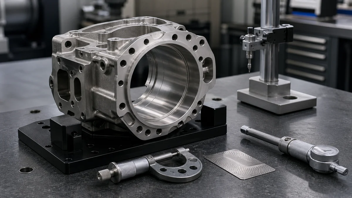
Tolerance, finish, and inspection should operate as one specification system. A close dimension without a defined function may trigger additional finishing passes and process checks. A fine surface requirement may change machining or add secondary processing. Documented inspection adds measurement and reporting effort. Applying all three everywhere compounds cost without necessarily improving the part.
| Feature class | Specification focus | Inspection requirement to define |
|---|---|---|
| Functional | Fit, sealing, bearing, motion, or load transfer | Selected dimensions, geometric controls, or roughness results |
| Assembly-related | Hole position, mating faces, and alignment | Datum-based verification and sampling scope |
| Cosmetic | Visible zone, texture, and permitted marks | Viewing criteria or approved comparison basis |
| Non-critical | Clearance or non-contact geometry | General drawing requirements unless a specific risk exists |
Use plus-or-minus tolerances when size alone controls function. Use GD&T when form, orientation, or position matters, with datums that represent assembly location and can be established during inspection. Surface finish should identify the parameter, value, unit, and exact face rather than rely on phrases such as “smooth finish.”
One common mistake is combining a blanket fine-finish note with tight general tolerances. This turns clearance pockets and hidden faces into precision features. Another is requesting a comprehensive inspection report without identifying characteristics, sample quantity, or reporting frequency.
The RFQ should state whether acceptance requires first-article results, in-process checks, batch sampling, final dimensional reporting, roughness readings, or documented checks of selected critical features. Inspection methods should follow geometry, access, tolerance, and datum relationships. A bore size, positional control, surface profile, and cosmetic face do not necessarily require the same measurement approach.
How Should the Part Envelope Be Matched to Titanium Stock?
Match the finished envelope to a practical titanium bar, plate, billet, or near-net form that satisfies grade, condition, and documentation requirements while limiting excess removal. Give suppliers controlled flexibility to review stock orientation and approved alternatives because purchased size, availability, workholding, chip volume, and scrap exposure affect total cost.
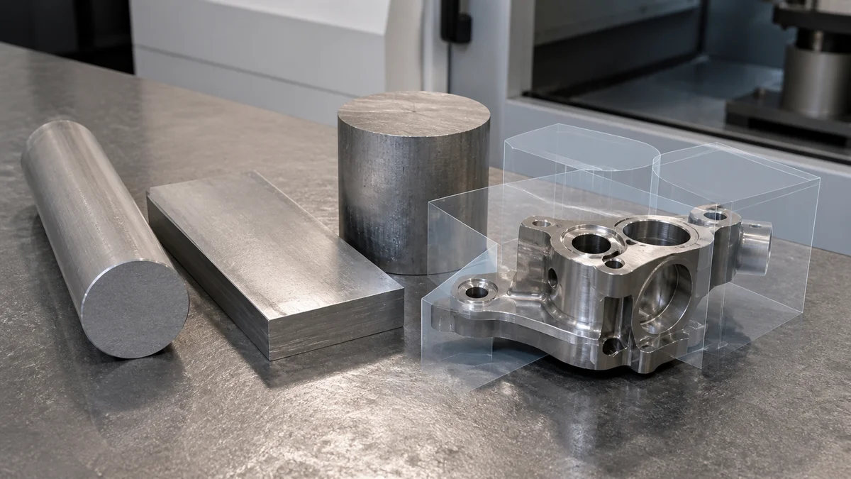
Titanium cost is influenced by the stock purchased, not only the material left in the finished component. A compact part cut from an unnecessarily large blank may require more purchased material, roughing, tool engagement, chip handling, and machine time. Stock selected too close to the final envelope, however, may leave inadequate material for workholding, cleanup, or datum establishment.
Review stock selection using these inputs:
- Exact titanium grade and condition
- Finished envelope and protruding features
- Candidate bar, plate, billet, or near-net form
- Part orientation within the starting stock
- Stable surfaces or extra material needed for workholding
- Required material documentation or heat-number traceability4
- Immediate quantity and projected repeat demand
- Permitted stock-form or geometry alternatives
Orientation can change the purchased blank dimensions and the volume removed. It may also determine how the workpiece is supported and which faces become primary datums. The orientation with the least apparent waste is not necessarily the best if it creates difficult clamping, long tool reach, added setups, or unbalanced material removal.
Should the drawing prescribe the raw blank?
Prescribe the stock form when engineering properties, traceability, grain or product-form requirements, or an established production route make it mandatory. Otherwise, state the required final characteristics and let the supplier propose an economical blank for approval.
Do not design around a published stock list without confirming availability. Regional inventory, source, grade, condition, dimensions, and quantity can vary. For repeat production, ask whether prepared blanks or another near-net option would change material use and setup planning, then compare sourcing commitment, machining, inspection, and revision exposure together.
Which Geometry Combinations Create Unstable Titanium Cutting?
The highest machining risk often comes from combining several demanding features in one region, such as a deep pocket, small internal radii, thin walls, restricted entry, interrupted cutting, and a fine finish. Simplify non-functional details and request DFM review before these interacting constraints are frozen into the controlled design.
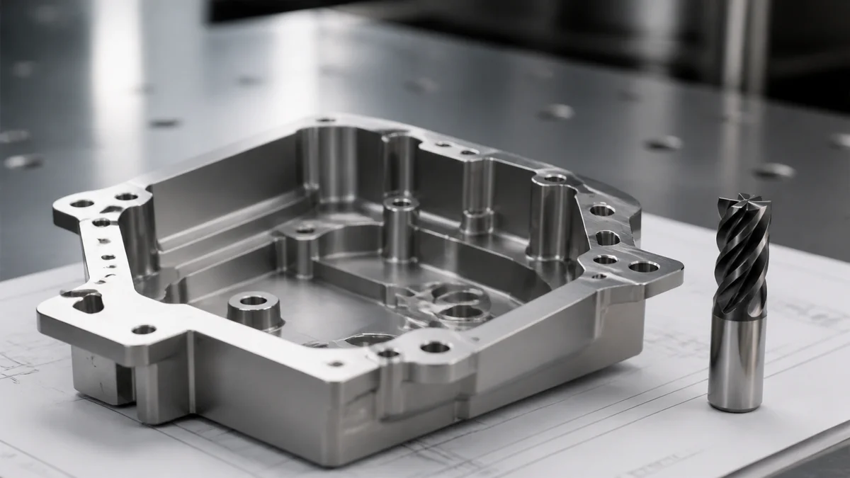
A feature that is manageable by itself can become expensive when combined with other constraints. A deep pocket may be practical with a broad opening but substantially more demanding when it also has small corner radii and a flexible wall. A thin rib may be manageable with open access but unstable when hidden behind a narrow entry and assigned a demanding finish.
Combinations that deserve focused review include:
- Deep cavities with small internal corner radii
- Thin walls beside heavy one-sided material removal
- Narrow entries requiring long tool overhang
- Interrupted surfaces carrying fine finish requirements
- Multi-face features with close cross-setup relationships
- Hidden geometry that is difficult to inspect
- Numerous nonstandard holes, threads, and radii that increase tool changes
Example: A pocket combines a thin perimeter wall, near-sharp corners, a fine finish on every internal face, and a tight profile control relative to a bore on another side. Reducing the pocket depth alone may not resolve the risk. A useful DFM review determines which wall is functional, which corner protects clearance, which surfaces need controlled roughness, and whether the bore relationship must cross setups.
The drawing should define delivered geometry, functional requirements, datums, finish zones, and acceptance criteria. It should not normally prescribe coolant pressure, feeds, speeds, ramping methods, or a specific toolpath. Those decisions depend on the supplier’s tooling, workholding, and process strategy.
The goal is not to make every titanium component simple. It is to prevent non-functional details from forcing unstable cutter engagement, excessive tool changes, conservative finishing, and broad inspection across the complete part.
What Should a Titanium CNC Machining RFQ Include?
A titanium CNC machining RFQ should combine the current model, controlled drawing, exact material requirement, demand context, critical specifications, inspection scope, revision, and delivery expectations. It should also distinguish functional and non-critical features and identify where suppliers may propose stock, geometry, setup, or process alternatives through DFM review.
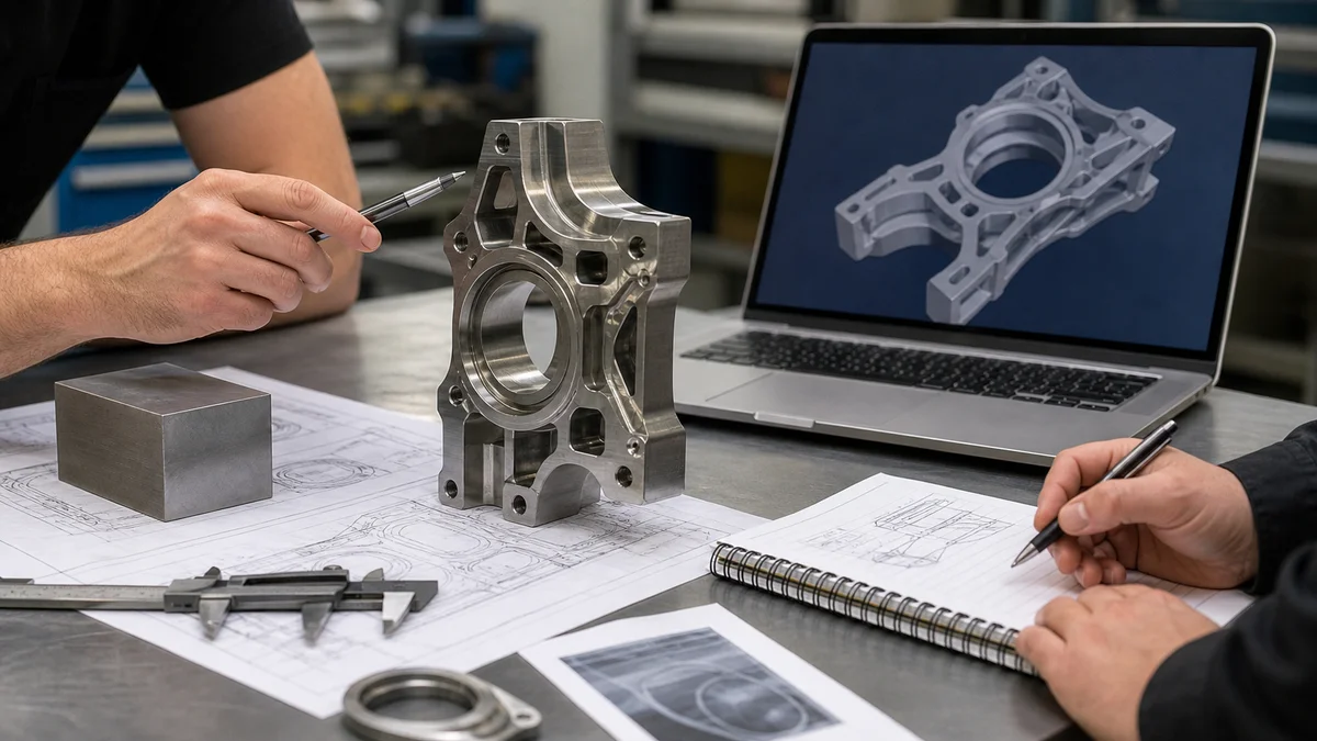
Use this approval checklist5 before requesting a quotation:
- ☐ 3D CAD model: Include complete external and internal geometry in a usable format.
- ☐ Controlled 2D drawing: State units, part identity, applicable drawing standard, notes, and active revision.
- ☐ Governing document: Resolve model-drawing conflicts or state which document controls.
- ☐ Titanium grade and condition: Avoid a generic “titanium” callout.
- ☐ Stock requirements: Identify mandatory product form, source restriction, buyer-supplied stock, or permitted alternatives.
- ☐ Material evidence: Request required material documentation or heat-number traceability explicitly.
- ☐ Quantity: State immediate demand, realistic quantity tiers, and projected usage when known.
- ☐ Production intent: Identify design learning, functional validation, pilot production, or repeat production.
- ☐ Critical tolerances: Separate functional and assembly features from ordinary geometry.
- ☐ GD&T and datums: Apply them where form, orientation, or location controls function.
- ☐ Surface finish: Mark the parameter, value, unit, and exact surfaces requiring control.
- ☐ Secondary operations: Define deburring, edge conditions, marking, coating, cleaning, assembly, or other required work.
- ☐ Inspection scope: State first-article, sampling, final reporting, roughness measurement, or selected full-inspection requirements.
- ☐ Revision status: Disclose expected design changes and use formal control after release.
- ☐ Delivery expectations: Include required timing, shipment structure, and partial-delivery needs.
- ☐ DFM flexibility: Identify acceptable changes to radii, pocket depth, stock orientation, setup strategy, or split construction.
A complete RFQ does not dictate every machining method. It gives suppliers enough evidence to plan material sourcing, tooling, workholding, setup, machining, finishing, and inspection while preserving the final characteristics that matter.
Ask each supplier to list assumptions and exclusions with the quotation. That makes differences in grade, stock form, inspection coverage, secondary operations, and production strategy visible before commercial comparison or order approval.
For a DFM recommendation, sample, or quotation, send the current 3D model, controlled 2D drawing, titanium grade and condition, quantity, prototype or production intent, critical tolerances, surface finish, inspection expectations, revision level, and delivery requirements. Mark non-negotiable features and identify where stock or geometry alternatives are acceptable.
References
-
An Intro to the CNC Machining Process - CNC drilling is a machining process that uses computerized multi-point drill bits to create smooth or threaded holes in the workpiece. ↩
-
Machinability performance investigation in CNC turning of ... - by S Swain · 2022 · Cited by 55 — Ti–6Al–4V is the largest useable titanium grade alloy in various engineering components due to its superior inherent properties like high strength to weight ... ↩
-
CoroMill® MR20 - Long overhang cavity milling. Chip evacuation … is the first choice for excellent chip formation and tool life in titanium. Long overhang cavity milling. Chip ... ↩
-
What Material Traceability and Mill Test Report (MTR) ... - Each heat number links a finished structural component back to its original melt, enabling full chain-of-custody verification. Without confirmed ... ↩
-
CNC Machining RFQ Checklist: Get Faster, Accurate Quotes - 1) Send both the drawing and the 3D model (when available). Best combo: 2D drawing (PDF) with dimensions, tolerances, notes, revision, and date. ↩