

Wall thickness, ribs, bosses, radii, and draft affect far more than the appearance of an injection molded part. Together, they shape resin flow, cooling, shrinkage, ejection, dimensional stability, mold construction, and the risk of sink or print-through on visible surfaces. Treating them as isolated CAD details can move preventable problems into tooling.
The right geometry depends on the exact resin grade, load path, surface texture, tolerance, cosmetic standard, production volume, and tooling strategy. These decisions provide a practical basis for DFM review, sample approval, and a mold-ready RFQ without relying on one unsupported set of universal dimensions.
How Should You Select Wall Thickness for an Injection Molded Part?
Select nominal wall thickness from the exact resin grade, flow length, structural loading, appearance requirements, and molding conditions. Keep walls reasonably uniform, document unavoidable variations, and obtain molding feedback before tooling because no single thickness specification is suitable for every resin and part geometry.

Wall thickness influences how molten resin fills the cavity, how quickly different regions cool, and how shrinkage develops. The useful question is not whether a wall appears thick enough in CAD. It is whether the selected resin can fill the complete geometry while the finished part supports its loads, mating features, and cosmetic requirements.
Create a nominal wall map during injection molding DFM review1. It should identify the baseline wall, local deviations, critical load regions, cosmetic zones, and assembly interfaces. Show where packaging, fastening, sealing, or clearance requirements prevent a uniform section. The molder can then review those exceptions with the gate location, flow path, cooling arrangement, and ejection strategy.
| Specification input | Manufacturing consequence | RFQ information |
|---|---|---|
| Exact resin grade | Changes flow and shrinkage assumptions | Grade, reinforcement, additives, approved alternatives |
| Flow length | Remote or restricted regions may be harder to fill | Complete internal geometry and gate preferences |
| Structural loading | Determines where stiffness is actually needed | Load direction and attachment points |
| Cosmetic requirement | Heavy sections may affect visible faces | Marked cosmetic zones and acceptance method |
| Production intent | Influences tooling and validation planning | Immediate quantity and expected annual demand |
A common mistake is writing only “uniform wall.” Uniformity is an objective, not permission to ignore a thick sealing land, thin clearance region, or local fastening feature. Mark each exception and explain its function. That gives the supplier room to propose a controlled transition, coring, or reinforcement without changing protected interfaces.
How Should Thick and Thin Wall Sections Transition?
Use gradual transitions and suitable radii wherever a molded wall changes thickness. Abrupt section changes can disrupt filling and cooling and increase the risk of sink, internal voids, residual stress, or warpage, especially near bosses, ribs, gates, and visible exterior surfaces.
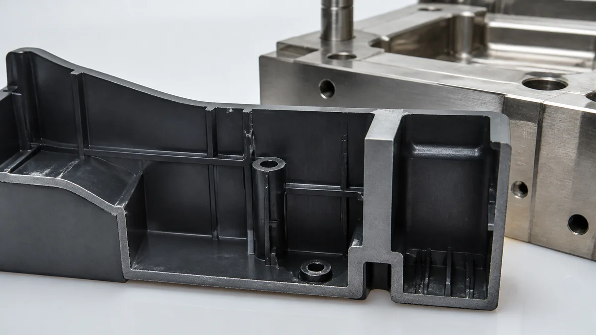
Distribute a wall-thickness change over a practical transition rather than creating a sharp step. A smoother change reduces concentrated material and gives resin flow and cooling a less abrupt geometry to negotiate. The transition still needs review against the resin grade, part envelope, mold direction, and surrounding features.
First locate every heavy section. Typical sources include mounting pads, sealing lands, boss connections, rib intersections, reinforced corners, and internal packaging features. Then classify the opposite surface as functional, hidden, or cosmetic. The same section change presents a different acceptance risk behind an internal face than behind a visible cover.
What if the heavy section cannot be removed?
Mark it on the controlled drawing and state why it exists. The supplier can evaluate coring, a longer transition, a revised rib arrangement, or another geometry change. Gate placement also belongs in this review because a wall transition may occur near the start or end of the resin flow path.
Example: A mounting pad merges directly into an exterior housing wall and creates a concentrated section behind a cosmetic face. Coring the pad, supporting it with ribs, and smoothing the junction may preserve the attachment function while reducing local mass. This is a DFM example, not a guaranteed correction for every resin or mold.
Review unavoidable wall transitions2 with nearby bosses, rib intersections, weld-line concerns, cooling access, and ejection. A cross-section alone cannot show whether the complete mold and filling strategy support the proposed geometry.
When Should You Add Ribs Instead of Increasing Wall Thickness?
Add ribs, curvature, beads, or gussets when the part needs directional stiffness but does not need a uniformly heavier wall. Simply increasing wall thickness can add cooling and shrinkage risk, so reinforcement should follow the actual load path, resin, appearance requirements, and mold-release conditions.

A thicker wall adds material across an entire region, including areas that may contribute little to the required stiffness. A rib or shaped section can instead reinforce a particular bending direction or transfer load between functional features. Base the choice on the load case, not on the assumption that more plastic automatically produces a stronger design.
| Reinforcement choice | Appropriate design question | Required molding review |
|---|---|---|
| Thicker wall | Does the whole section require added material? | Cooling, shrinkage, and visible-surface effects |
| Rib | Is stiffness needed along a defined path? | Thickness, height, filling, draft, and sink risk |
| Curvature or bead | Can section shape provide stiffness? | Part envelope, pull direction, and appearance |
| Gusset | Must load transfer between intersecting features? | Junction mass, radius, ejection, and access |
| Different resin | Does the material fit the load and environment? | Grade, reinforcement, flow, shrinkage, and validation |
The specification should identify force direction, attachment points, supported span, mating components, and the functional acceptance criterion where one exists. Avoid notes such as “add ribs for strength.” That phrase does not tell the molder where the load travels or which exterior faces must remain cosmetic.
Reinforcement geometry can also create secondary problems. A rib may stiffen a wall but obstruct resin flow, ejection, a slider, or an internal component. Curvature may improve stiffness while changing the product envelope. Compare the alternatives using the complete geometry, exact material grade3, surface texture, tolerances, and production intent before committing mold steel.
How Should Rib Geometry Be Specified for Filling, Ejection, and Appearance?
Specify rib thickness, height, spacing, root radius, draft, and location as one coordinated feature. Heavy ribs can produce sink or print-through on the opposite wall, while tall thin ribs may be difficult to fill or eject with the selected resin and mold layout.
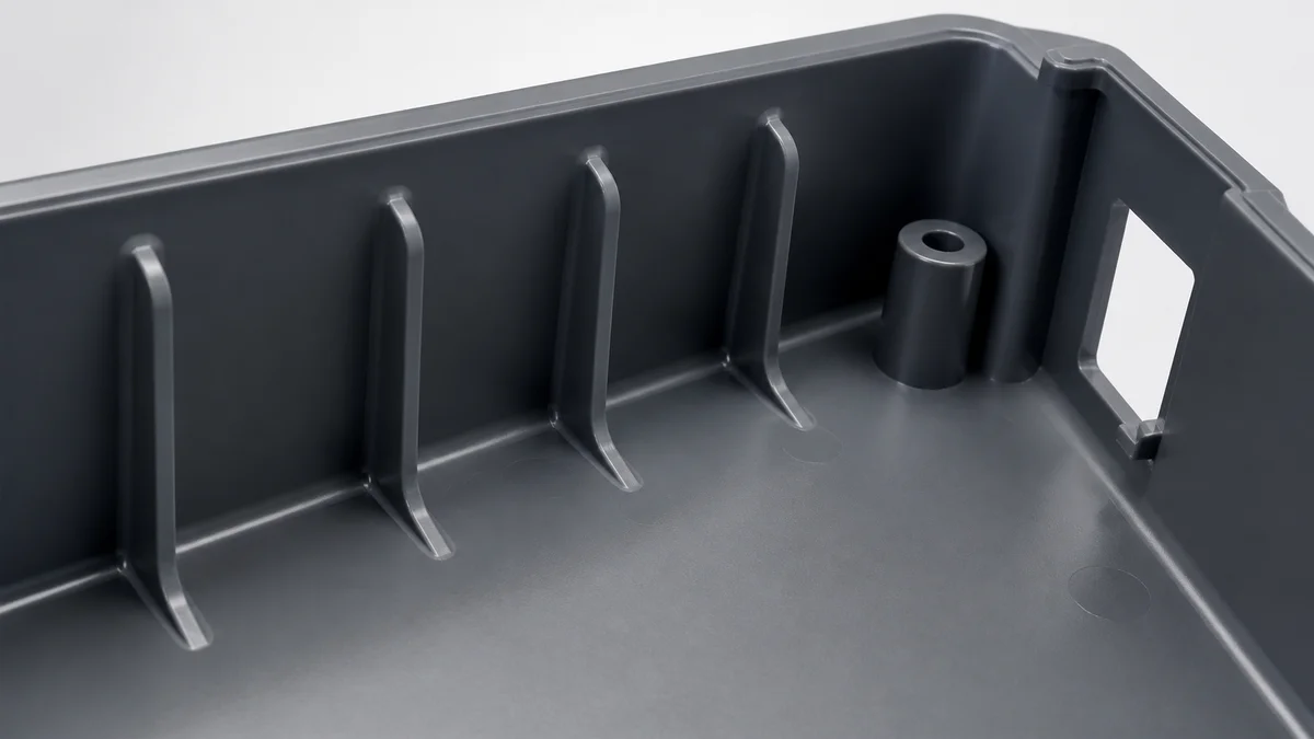
A rib should reinforce a known load path without becoming a hidden heavy section. Its manufacturability depends on the relationship between the complete rib profile, supporting wall, resin, gate location, and pull direction. Checking thickness or height in isolation can miss how the feature fills, cools, and releases.
Use this rib design review sequence4:
- State the rib’s structural purpose and expected load direction.
- Classify the opposite wall as cosmetic, functional, or hidden.
- Review rib thickness against the supporting wall and nearby intersections.
- Check height and spacing against the flow path and ejection direction.
- Add a suitable root radius rather than leaving a sharp junction.
- Apply draft to faces that move against mold steel during release.
- Find converging ribs that create concentrated material.
- Check clearance from gates, core pins, inserts, sliders, and internal components.
Tall, narrow ribs may appear material-efficient but present a restricted filling path. Heavy ribs may be easier to fill yet cool unevenly and leave visible print-through. The practical solution remains conditional: changing the resin, gate strategy, rib layout, wall relationship, or cosmetic requirement can change the preferred geometry.
A frequent specification mistake is dimensioning the rib but omitting its purpose and the status of the opposite surface. The supplier then sees the shape without knowing whether stiffness, appearance, or packaging has priority. Functional notes make rib thickness and draft recommendations easier to assess without weakening protected requirements.
How Should Bosses Be Cored and Supported?
Design fastening bosses as cored structural features and transfer their loads through controlled ribs or gussets. Avoid treating a boss as a solid cylinder attached to a wall because concentrated mass can disrupt filling and cooling and contribute to sink or warpage behind visible surfaces.
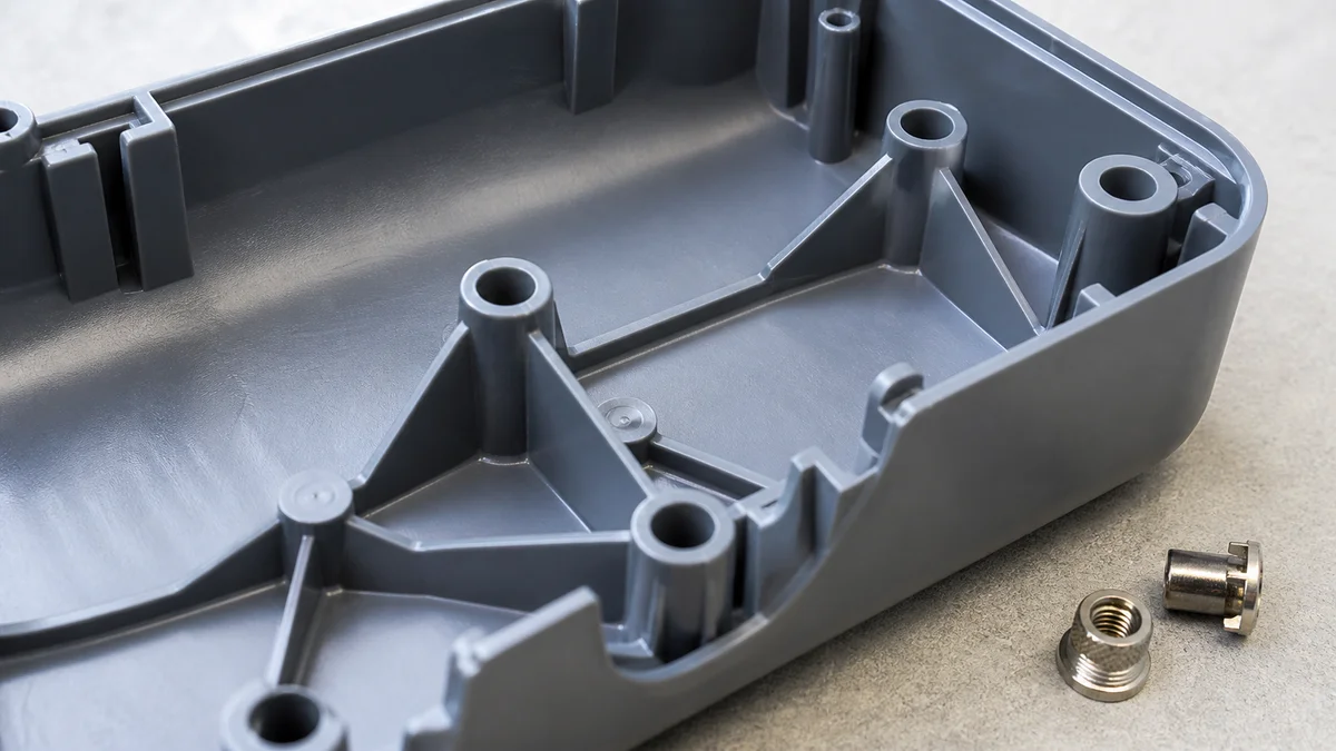
A boss normally provides fastening, locating, insert, or assembly support. That function should govern its bore, surrounding material, load direction, and connection to the part. An unnecessarily solid section adds concentrated mass where a cored form and controlled supports may carry the load more appropriately.
Review boss purpose, fastener or insert details, surrounding wall thickness, boss-to-wall connection, rib arrangement, load direction, draft, ejection, and nearby cosmetic surfaces together. If the boss receives an insert, state the insert family, installation responsibility, and production sequence. These details let the supplier evaluate the complete fastening feature rather than only its outside diameter.
Scenario: Injection molded cover DFM. A cover contains thick bosses joined directly to uneven exterior wall sections. The outside face is cosmetic, while the bosses carry assembly screws. Before tooling, the design team treats the bosses as cored features, aligns supporting ribs with the screw-load paths, and smooths the wall transitions. This teaching scenario illustrates how early review can address sink and warpage risk; it is not a customer case or a promised result.
Should every boss connect directly to the outer wall?
No. The appropriate connection depends on packaging, load transfer, resin flow, and mold construction. A rib-supported boss may reduce concentrated material, but those ribs still require controlled thickness, spacing, radius, and draft. Review molded boss design5 as part of the whole fastening system, including the mating hardware and assembly intent.
How Should Draft Be Specified for Reliable Mold Ejection?
Apply draft to every face that moves relative to the mold during ejection, but determine the required angle from resin shrinkage, draw depth, texture, polishing direction, steel condition, and inside or outside geometry. One blanket draft value is rarely an adequate specification.
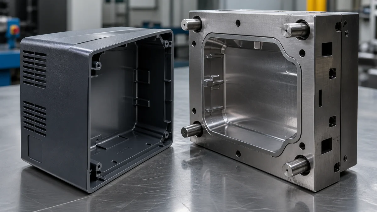
Draft is the intentional taper that allows a molded surface to separate from the core or cavity. Begin by establishing the primary pull direction, then identify every face that moves relative to mold steel. Features formed by sliders, lifters, or other mold actions require the same review in their individual movement directions.
The drawing and RFQ should identify:
- Primary and secondary pull directions.
- Inside and outside faces requiring draft.
- Draw depth for walls, ribs, bosses, and pockets.
- Textured or specially polished surfaces.
- Cosmetic zones affected by taper or release marks.
- Mating, sealing, or locating features that restrict draft.
- Intentional exceptions where function limits taper.
- Parting-line and ejection preferences.
Texture changes the mechanical interaction between the part and mold surface during release. Polishing direction and steel condition can also influence movement. Resin shrinkage adds another variable, so the draft angle6 should be reviewed after the exact molding material is defined rather than copied from an unrelated design.
Example: A deep internal wall and a shallow textured exterior wall receive the same blanket draft note. Their draw depths, release conditions, and surface priorities differ. Specifying them separately gives the mold designer room to protect ejection without unnecessarily changing a critical interface.
Where a functional face cannot accept the proposed taper, flag it clearly. The toolmaker can then assess a revised parting strategy, mold action, local geometry change, or controlled straight condition. A draft exception is a tooling decision, not merely an omitted CAD feature.
How Do Ribs, Undercuts, and Draft Affect Mold Construction?
Review ribs, undercuts, draft, shutoffs, parting lines, sliders, lifters, core pins, and ejection before CAD release. Features that appear simple on the finished part can require additional mold actions, difficult steel conditions, or maintenance-sensitive details that affect tooling cost and schedule.
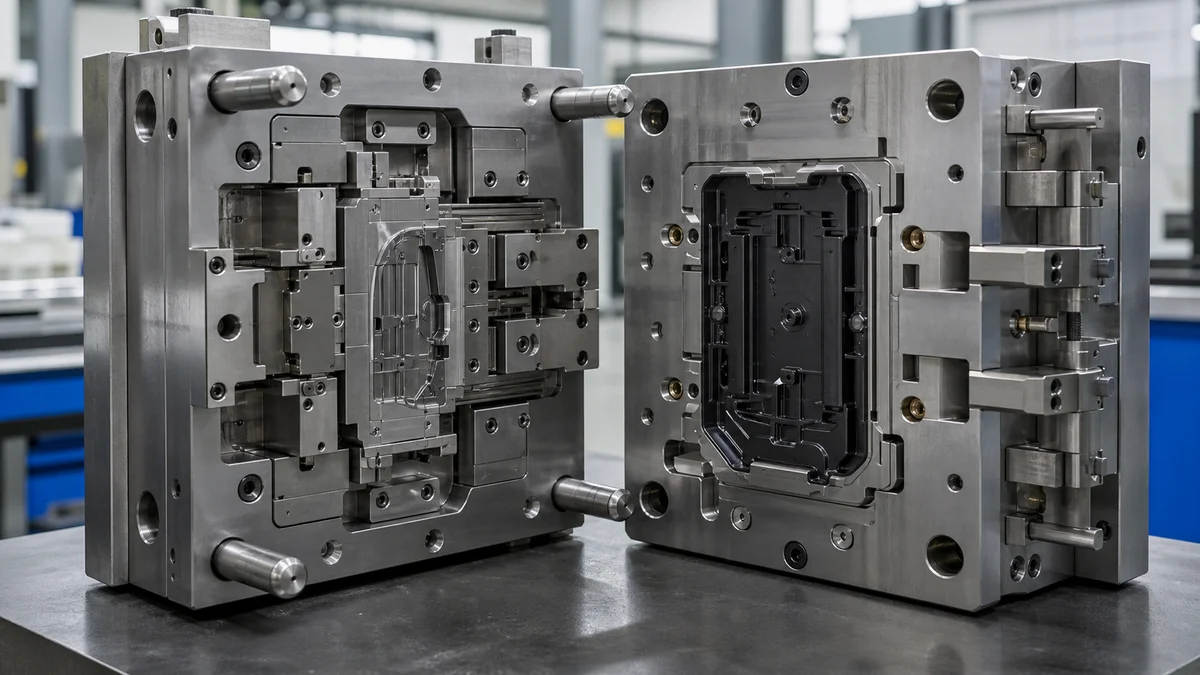
Mold construction starts with how the part separates from the core and cavity. A feature that blocks straight release may require a slider, lifter, revised parting line, flexible feature, or geometry change. Each additional action should protect a defined function because it adds tooling interfaces that must be designed, assembled, validated, and maintained.
| Part feature | Mold consequence | DFM question |
|---|---|---|
| Deep rib | Restricted filling, draft demand, and narrow mold steel | Can it be shortened, moved, widened, or opened? |
| Undercut | Blocks release in the primary pull direction | Is its retention or clearance function essential? |
| Shutoff | Creates a meeting surface between mold elements | Is the geometry accessible and maintainable? |
| Slider or lifter | Adds a moving mold action | Can the feature align with a simpler pull direction? |
| Core pin | Forms a hole or cored region | Is it supported and compatible with resin flow? |
| Parting line | Places a visible or functional witness line | Which surfaces can accept that condition? |
Show intended pull directions in the model or controlled drawing. Mark undercuts, insert details, parting-line restrictions, gate preferences, and areas where witness lines or ejection marks are unacceptable. Separate fixed functional requirements from preferences that may move during DFM.
Tooling complexity is not proportional to the number of CAD features. A small snap, rib, or side opening can control the complete mold strategy when it blocks release. Early review of injection mold actions7 lets the buyer preserve the function while allowing simpler construction where geometry permits.
Where Should Radii Be Added to Improve Flow and Mold Durability?
Add suitable radii and gradual transitions at wall junctions, rib roots, boss connections, and internal corners. Rounded geometry can support resin flow, reduce stress concentration, and avoid sharp mold-steel details that may be difficult to machine, polish, or maintain.

Radii serve both the molded part and the tool. In the part, a radius softens a section change and reduces a sharp stress concentration. In the mold, it avoids an unnecessarily sharp steel feature that may have restricted machining or polishing access and may be less practical to maintain.
Begin with internal wall junctions, then inspect rib roots, boss supports, gussets, pockets, and transitions around openings. Evaluate each radius with the adjoining wall thickness and local material concentration. A large fillet added without section analysis can create another heavy region, so “add radius” is not a complete specification.
Which corners should remain functionally sharp?
Some interfaces need a controlled corner for clearance, sealing, locating, or appearance. Identify the precise functional area rather than applying a blanket sharp-corner note. The toolmaker can then assess whether normal mold construction supports the requirement or whether the mating component should receive relief.
A common mistake is leaving nominally sharp internal corners in the 3D model without stating whether they are functional or unfinished CAD geometry. The supplier must then assume either a practical radius or more difficult toolmaking. Explicit mold corner radii8 reduce that ambiguity.
Review each radius with resin flow direction, gate location, texture, polishing access, parting, and ejection. A radius that improves one junction can interfere with an insert, mating component, or shutoff. The target is a controlled transition that supports function without creating avoidable mass or fragile mold steel.
How Should Tolerance, Warpage, and Sample Approval Be Defined?
Apply tolerances and warpage limits only where fit, function, or appearance requires control, then define the measurement condition and sample-approval evidence. Injection molding reflects resin shrinkage, cooling, cavity conditions, and production variation, so every CAD dimension should not receive the same acceptance requirement.
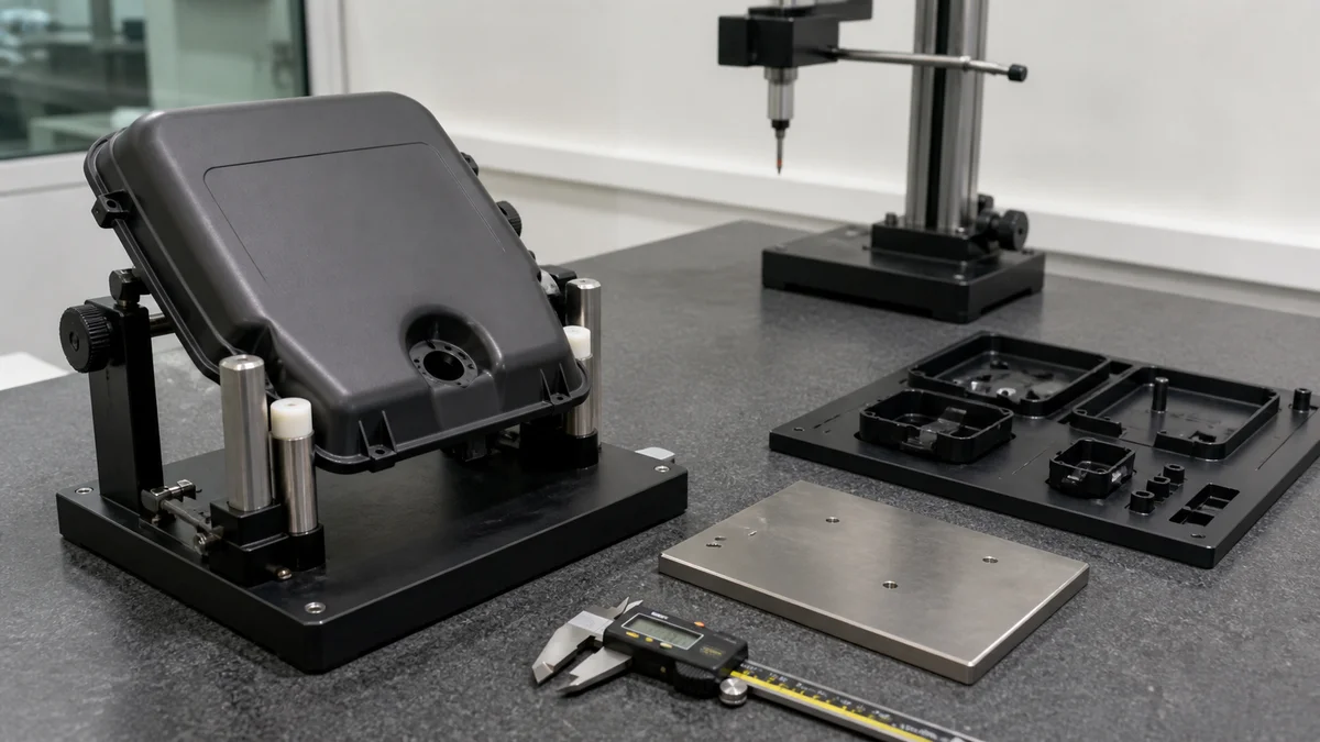
Classify molded features as functional, assembly-related, cosmetic, or non-critical. Locating interfaces, sealing regions, fitted openings, and motion-controlling features may justify explicit dimensional control. Cosmetic zones need a defined appearance method, not an arbitrary dimensional tolerance. Ordinary geometry should not be priced and inspected as though it governs assembly.
The molded part approval plan9 should state:
- Critical dimensions and applicable tolerances.
- Warpage criteria, reference features, and measurement condition.
- Whether measurement occurs free or in a defined fixture.
- Conditioning requirements for the selected resin, when applicable.
- Cosmetic zones, viewing conditions, and approved comparison samples.
- Functional or assembly tests required for approval.
- Cavity identification requirements where relevant.
- First-sample scope and characteristics included in the report.
- Production sampling or continuing inspection expectations.
- Events that trigger renewed approval, such as material or engineering changes.
“Part must be flat” is not an adequate warpage specification. Identify the surface or relationship that affects assembly, how the part is supported, and what function the limit protects. Likewise, one sample assembling successfully does not define ongoing dimensional acceptance.
Scenario: A cover rocks on its mating frame, but the drawing controls only overall length and width. The useful requirement is the mounting relationship or warpage condition affecting assembly, not tighter unrelated dimensions. This teaching example shows why the inspection method must follow function.
Define inspection evidence before quotation so tooling validation, measurement, reporting, and potential corrective iterations are visible in the approval route.
How Should the Manufacturing Process Be Named in the Specification?
State plastic injection molding explicitly when molten resin will fill a dedicated mold and the part will cool and eject from that tooling. Do not use CNC machining, CNC turret punching, metal stamping, sheet metal fabrication, or the ambiguous term CNC turret punching, CNC punch press, CNC-controlled stamping equipment, or metal stamping depending on the actual process as interchangeable process names.

Correct process naming prevents suppliers from quoting different materials, geometry assumptions, and tooling routes. Injection molding is a polymer process governed by resin flow, cooling, shrinkage, parting, draft, gates, and ejection. Its wall, rib, boss, and undercut rules do not transfer directly to stock removal or sheet forming.
| Process | Operating principle | Specification focus |
|---|---|---|
| Plastic injection molding | Molten resin fills a mold, cools, and ejects | Resin, walls, draft, gates, shrinkage, tooling, samples |
| CNC machining | Cutting tools remove material from solid stock | Material grade, tool access, setups, tolerance, finish |
| CNC turret punching or CNC punch press work | Programmed punches cut or form sheet | Grade, gauge, burr direction, punch tools, formed features |
| Metal stamping | Dedicated dies cut or form sheet material | Strip material, die design, forming, springback, volume |
| Sheet metal fabrication | Combines cutting, bending, punching, joining, and finishing | Gauge, bends, hardware, flatness, assembly condition |
“CNC turret punching, CNC punch press, CNC-controlled stamping equipment, or metal stamping depending on the actual process” is not one standard process term. It may be intended to mean turret punching, a CNC punch press, CNC-controlled stamping equipment, or general die stamping. Replace it with the actual process before requesting price or DFM feedback.
Process comparison is still valid when it is explicit. A prototype program may compare CNC-machined plastic with injection molding, but the RFQ should state the validation goal, material form, quantity, design maturity, and whether the molded version will be redesigned. The manufacturing process terminology10 should describe the route clearly rather than function as a loose synonym for automation.
What Should a Mold-Ready Injection Molding RFQ Include?
A mold-ready RFQ should combine controlled design files with exact resin, geometry, appearance, volume, tooling, tolerance, inspection, approval, revision, and delivery requirements. Complete information lets the supplier evaluate wall thickness, ribs, bosses, draft, mold actions, validation work, cost, and schedule without hidden assumptions.

Send each supplier the same controlled package so quotations reflect comparable requirements. The 3D model communicates complete geometry; the 2D drawing controls specifications that geometry alone may not express. Identify the active revision and state which document governs if the files conflict.
Injection molding RFQ and approval checklist11
- Current 3D CAD model and controlled 2D drawing.
- Part number, units, revision level, and governing document.
- Exact resin grade, reinforcement, color, additives, and approved alternatives.
- Immediate quantity, expected annual demand, lot sizes, and production intent.
- Prototype, pilot, bridge, or repeat-production stage.
- Nominal wall map and unavoidable thick or thin regions.
- Functional purpose of ribs, bosses, gussets, inserts, and snap features.
- Fastener or insert details and installation responsibility.
- Primary and secondary pull directions.
- Draft, texture, polishing, and cosmetic-zone requirements.
- Parting-line, gate, ejection-mark, and weld-line preferences or restrictions.
- Undercuts, sliders, lifters, shutoffs, core pins, and other mold actions.
- Critical tolerances, assembly interfaces, and warpage criteria.
- Surface appearance requirements and approved samples where applicable.
- Measurement condition, sample tests, and inspection-report scope.
- Cavity identification or production sampling requirements when needed.
- Tooling ownership, maintenance responsibilities, and program demand.
- Packaging and delivery expectations.
- Permission for DFM alternatives and a list of requirements that cannot change.
Avoid requesting a quotation from a model alone when resin, tolerance, texture, volume, and approval requirements remain undefined. Those gaps force suppliers to use different tooling and validation assumptions. A complete package does not replace DFM discussion; it makes proposed geometry changes, inspection work, and production plans directly comparable.
For a DFM recommendation, sample plan, or quotation, send the current 3D model, controlled 2D drawing, exact resin grade, quantity, prototype or production intent, critical tolerances, surface finish or texture, inspection expectations, revision level, and delivery needs. Mark wall transitions, ribs, bosses, draft restrictions, undercuts, cosmetic zones, and preferred mold directions.
References
-
Injection Molding Wall Thickness: Design Guidelines & Best ... - Maximum practical wall thickness for conventional injection molding is 0.250" (6.35mm). Beyond this limit, parts suffer from: Excessive ... ↩
-
Solving Wall Thickness Issues in Molded Parts - Very thick parts will lead to cosmetic and structural problems like voiding and warping, while very thin parts may reduce structural strength, or not fill at ... ↩
-
Design Stronger Molded Parts: Ribs, Gussets, and Materials - It's important to note that ribs and gussets should be no more than 60 percent of nominal wall thickness. These features are kept thinner than the primary walls ... ↩
-
Internal Rib Draft Angle for Injection Molding - The minimum draft angle for internal ribs is typically 0.5° per side. Rib height, base thickness, spacing, and root radius all affect packing, cooling, and ... ↩
-
Designing Bosses For Injection Molding: A Complete Guide - Ensure the boss is cored from the underside and wall thickness follows the 0.5-0.6x rule to prevent sink marks on the cosmetic surface. ↩
-
Draft Angles in Injection Molding: A Complete Guide - A widely accepted guideline is to add 1 to 1.5 degrees of draft for every 0.001 inches (0.025 mm) of texture depth. ↩
-
Injection Molding Undercuts for Plastic Part Designs - An undercut that interferes with the separation of the core and cavity may require the use of a slider, lifter, or hand-loaded insert to release the part. ↩
-
Design Solutions Guide - Fillets and Radii. Sharp corners should be avoided. They are the number one cause of part failure, stress concentrations, poor flow patterns and increased ... ↩
-
Injection Molding Tool Validation | Mold Acceptance, CMM ... - The mold should be validated within the agreed press tonnage, injection capacity, mold temperature range, cooling setup, resin condition, and process window. ↩
-
CNC Machining vs Stamping: Which Is Best for Your Project? - We house metal stamping, CNC machining, laser cutting, turret punching, bending, powder coating, and assembly under one roof. This centralized model streamlines ... ↩
-
Injection Molding RFQ Template & Buyer Checklist - Use this injection molding RFQ template to specify files, material, volume, tooling, quality, and commercial details for comparable supplier quotes. ↩