
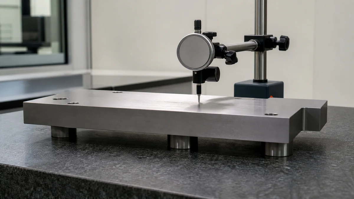
Flatness and parallelism often appear together on CNC machining drawings, but they protect different aspects of part function. Flatness controls the form of an individual surface. Parallelism controls how a surface, axis, or center plane is oriented relative to a datum. Selecting the wrong control can leave sealing, mounting, alignment, or motion requirements undefined even when every size dimension passes inspection.
A reliable specification starts with the functional interface, then connects the geometric control to material stability, workholding, machining sequence, final part condition, and an agreed inspection method. That connection helps prevent conflicting quotation assumptions and avoidable acceptance disputes.
Should You Specify Flatness or Parallelism?
Specify flatness when one surface must remain sufficiently even by itself. Specify parallelism when a surface, axis, or center plane must maintain its orientation relative to a functional datum. Flatness needs no datum reference; parallelism does.
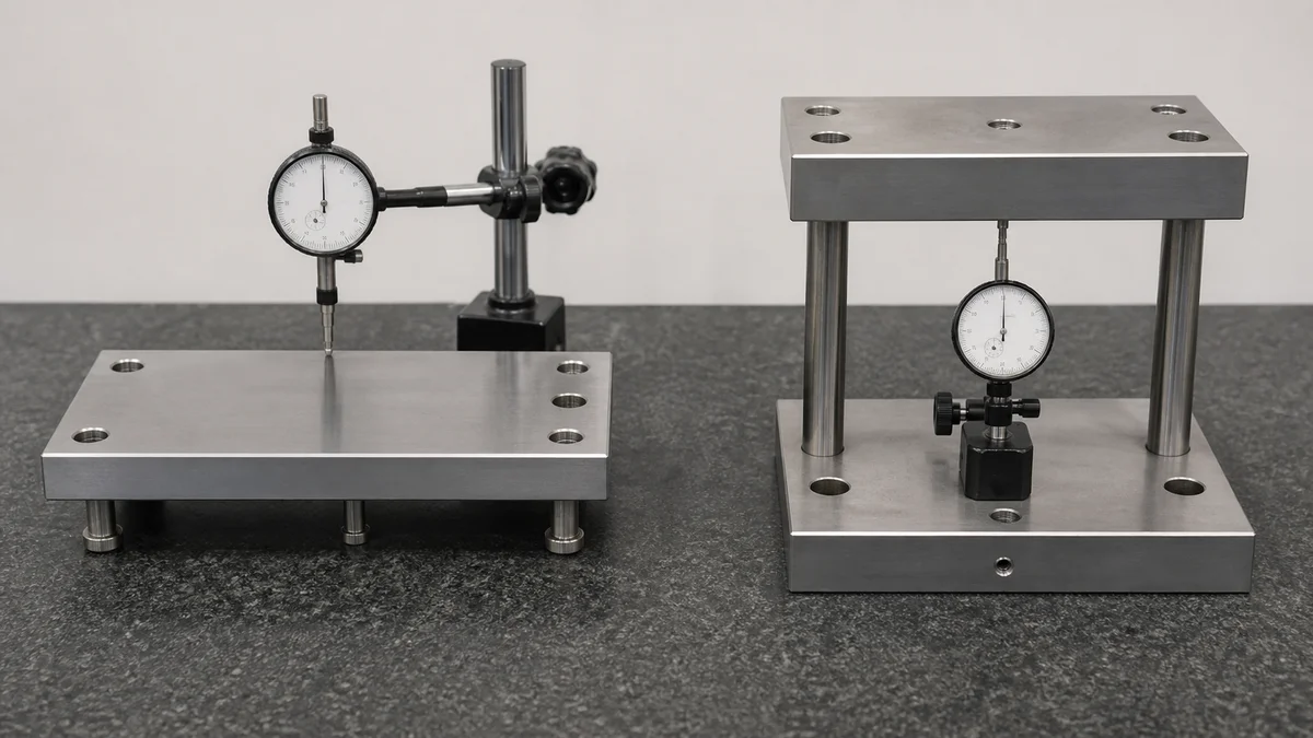
Flatness establishes a tolerance zone between two parallel planes. Every point on the controlled surface must remain inside that zone, but the zone is not oriented to another feature. It is therefore a form control1.
Parallelism also establishes an oriented tolerance zone, but its orientation comes from a referenced datum. For a controlled surface, the zone is commonly two planes parallel to the datum plane. Depending on the feature and drawing definition, parallelism can also control an axis or center plane.
| Functional requirement | Appropriate control | Datum required? | Drawing application |
|---|---|---|---|
| Keep one face even independently | Flatness | No | Sealing face or mounting pad |
| Keep one face aligned with a locating face | Parallelism | Yes | Opposed mounting surfaces |
| Keep a bore or shaft axis aligned to a reference | Parallelism | Yes | Guided or rotational motion |
| Protect both surface form and face-to-face orientation | Flatness plus parallelism, where justified | Only for parallelism | Precision mating interface |
The choice should follow the failure being prevented. A seal may depend mainly on the contact face having acceptable form. A slide or guided component may depend on the relationship between its guiding surface and the face that locates the part.
Example: A machined cover face can satisfy flatness yet remain angled relative to the housing base. If assembly requires those faces to stay aligned, flatness alone does not protect the relationship. Parallelism must reference the datum that represents how the housing actually locates.
Can a Thickness Tolerance Control Flatness or Parallelism?
A thickness tolerance controls feature size, not automatically the form of either surface or its orientation to a datum. Add flatness or parallelism only when sealing, mounting, guiding, or alignment depends on geometric conditions that size limits cannot protect.
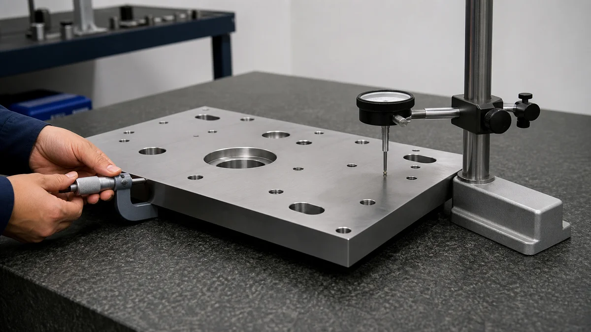
Thickness, flatness, and parallelism answer different specification questions. Thickness defines the permitted size between opposed surfaces under the governing drawing rules. Flatness limits variation across one surface. Parallelism limits orientation relative to a datum. A component can therefore meet its thickness limits while remaining unsuitable for a mounting or sealing interface.
Use the controls according to function:
- Apply a size tolerance when thickness, clearance, envelope, or fit between opposed surfaces is the main requirement.
- Apply flatness when surface form affects contact, sealing, support, or stability.
- Apply parallelism when a face, axis, or center plane must remain oriented to a functional datum.
- Combine the controls only when size, form, and orientation independently affect acceptance.
Tightening thickness to make two faces appear parallel is poor specification practice. It increases machining and inspection effort without identifying which surface locates the component or how the other face must relate to it. Chained dimensions can introduce additional tolerance stack-up2 without controlling the intended orientation.
If rocking on a base is the concern, control the mounting face. If an upper face must align with equipment located from the base, establish the base as a datum and apply parallelism where justified. When both overall thickness and face orientation affect assembly, define both requirements directly rather than expecting one to imply the other.
How Should You Select a Datum for Parallelism?
Choose a datum that represents how the part locates in assembly and can be established repeatably during machining and inspection. A broad, stable, accessible mounting face is generally more useful than a small, interrupted, unfinished, or functionally unrelated surface.
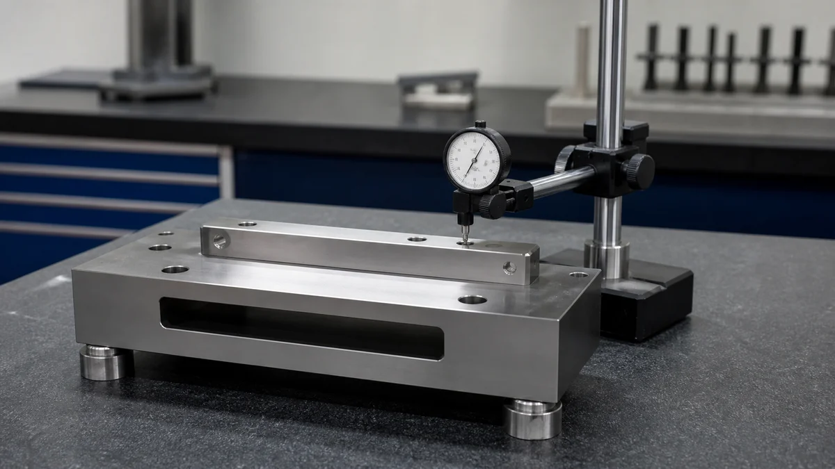
A datum is a theoretically exact reference3 derived from a physical datum feature. For parallelism, that reference establishes the orientation of the tolerance zone. Datum selection therefore determines whether the control protects the real assembly and whether different inspectors can reproduce the evaluation.
Begin with functional part location. A mounting face may be suitable when it seats against a frame or housing. A bore axis may be more meaningful when rotation or guided motion establishes alignment. The physical feature must provide stable, accessible geometry from which the intended reference can be established.
Rank possible datum features by four considerations:
- Does the feature locate the component in service?
- Is it sufficiently stable to establish repeatable contact or measurement?
- Can machining and inspection access it without an artificial setup?
- Will it remain unchanged through heat treatment, coating, or other secondary operations?
Small pads, interrupted lands, flexible walls, unfinished stock surfaces, and inaccessible internal features can create unstable datum simulation. A cosmetic boss or convenient drawing edge is also a weak choice when it does not represent assembly location.
Where parallelism is critical, the drawing should identify the datum explicitly and define the final inspection condition. If the part must be restrained during use or measurement, that condition should be stated so manufacturing and acceptance do not establish different references.
Which Geometry and Material Conditions Make Flatness Difficult?
Flatness becomes harder to maintain when geometry is flexible, material removal is unbalanced, or the stock contains residual stress. Thin plates, broad faces, one-sided pockets, interrupted surfaces, uneven sections, heat treatment, and sensitive clamping conditions require part-specific review.
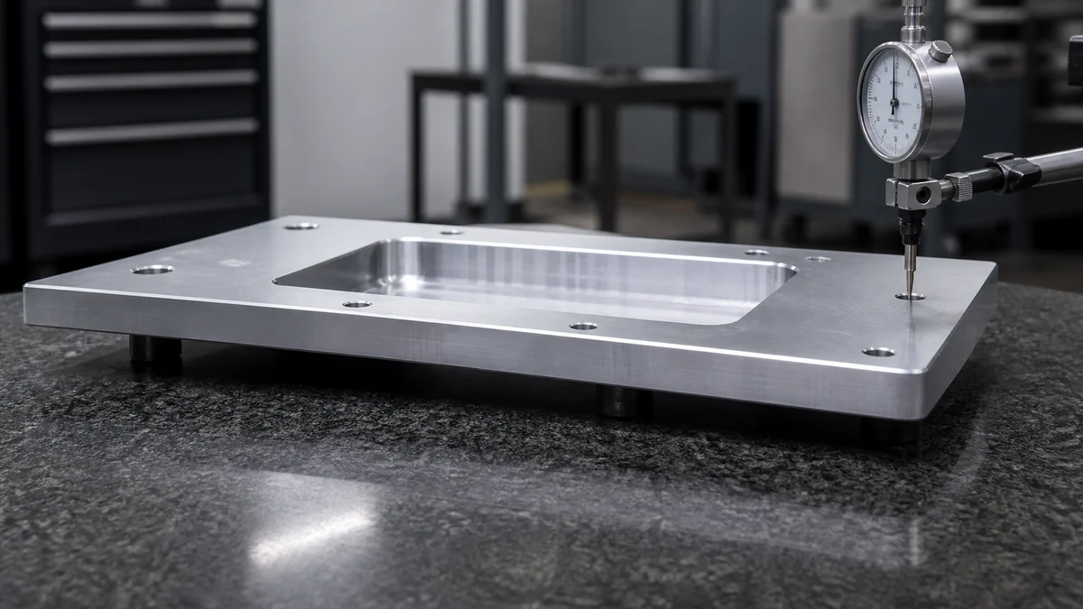
The same flatness value can represent very different manufacturing risk on a compact block and a broad, thin plate. Feasibility depends on the complete part envelope, material grade and condition, stock form, wall thickness, pocket layout, workholding, and final processing sequence.
| Risk condition | Practical consequence | Information needed for review |
|---|---|---|
| Thin or tall sections | Cutting and clamping forces can deflect the surface | Minimum wall thickness and unsupported height |
| Broad faces | Small bow or twist becomes significant across the span | Overall face dimensions and functional contact area |
| One-sided pockets | Uneven removal can release internal stress asymmetrically | Pocket depth, remaining floor thickness, and removal side |
| Interrupted surfaces | Pads, holes, and slots complicate support and sampling | Complete surface geometry and inspection access |
| Abrupt section changes | Thick and thin regions may move differently | Section views and stock condition |
| Heat treatment or finishing | Later processing can alter the accepted geometry | Full operation sequence and final acceptance stage |
Machining distortion from residual stress4 is especially relevant when substantial material is removed from one side. Plate, bar, extrusion, heat-treated stock, and stress-relieved stock can behave differently even when their nominal material family is the same.
Example: A broad aluminum plate with a deep pocket on one side may appear stable while clamped. Once released, reduced stiffness and redistributed stress can allow bowing. A realistic review therefore needs the pocket geometry, minimum wall sections, material condition, critical face, and free-state or restrained inspection requirement.
Surface finish can add another interaction. Extra passes or secondary processing may change the final form, so functional roughness and flatness should be evaluated in the same manufacturing sequence without treating one requirement as a substitute for the other.
When Does the Tolerance Require a Different Machining Route?
A flatness or parallelism requirement may justify a different route when ordinary machining cannot reliably protect the functional surface in its final condition. Material stability, geometry, tolerance, finish, heat treatment, inspection, quantity, and production intent should guide that decision.
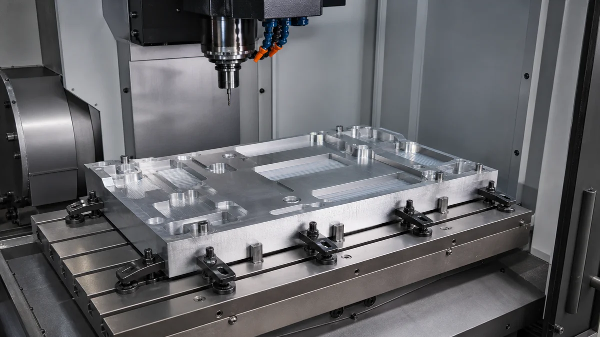
A demanding geometric control can change stock selection, programming, workholding, setup count, cutting sequence, secondary processing, and inspection. The requirement should be disclosed before quotation because grinding, lapping, stress relief, or elaborate fixturing is not automatically necessary for every controlled surface.
| Part or specification condition | Possible process response | Manufacturing purpose |
|---|---|---|
| Heavy removal from one side | Balanced roughing5 or staged machining | Reveal movement before final passes |
| Residual-stress concern | Stress relief when suitable for the material and route | Improve stability before final sizing |
| Flexible plate or wall | Distributed clamping, backing support, or revised sequence | Limit fixture-induced deformation |
| Critical final face | Reserved finish stock and a later finishing pass | Retain correction allowance |
| Heat treatment after roughing | Final machining after treatment | Correct movement in the required final state |
| Demanding planar form and finish | Grinding or lapping where geometry permits | Match the finishing process to acceptance needs |
| Unstable or undersized starting blank | Different stock form or thicker blank | Provide stiffness and cleanup allowance |
These are conditional planning options, not mandatory operations. Grinding may suit accessible planar faces, while lapping may be considered when both surface form and surface condition justify it. Interrupted faces, pockets, thin sections, and restricted access can limit either route.
The drawing must identify when acceptance applies. If heat treatment, anodizing, coating, or assembly follows machining, specify whether the geometric control applies before or after that operation. Quantity also matters: a prototype intended for fit evaluation may use different workholding and inspection from stable repeat production.
For a demanding surface, request a concise process-route explanation covering starting stock, major roughing stages, release or reclamping checks, final operation, and inspection condition. That record exposes incompatible assumptions before they become approval or schedule problems.
How Should Flatness and Parallelism Be Inspected?
Inspection should follow the governing GD&T standard, datum structure, part-support condition, surface accessibility, tolerance risk, and required evidence. Measurement methods and data-processing strategies can report different values from the same physical surface, so acceptance details must be agreed before production.
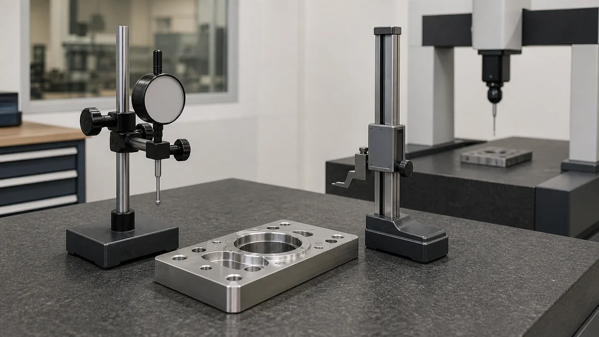
Flatness inspection evaluates surface form without establishing a datum. Parallelism inspection first establishes the referenced datum and then evaluates the controlled feature in that orientation. Drawing interpretation should follow the same GD&T standard and revision for manufacturing, inspection, and approval.
| Inspection approach | Suitable application | Specification-sensitive variables |
|---|---|---|
| Surface plate and indicator | Accessible planar surfaces and comparative sweeps | Support locations, sweep pattern, indicator resolution, and datum simulation |
| Height gauge with suitable setup | Relative height or orientation checks | Reference establishment, access, and measurement path |
| Coordinate measurement6 | Structured point collection and datum alignment | Point density, fitted-data method, filtering, and alignment strategy |
| Optical measurement | Visible surfaces or dense non-contact data | Reflectivity, line of sight, processing method, and surface condition |
No device should be prescribed merely as a quality signal. Geometry, accessibility, tolerance, quantity, and evidence requirements should determine the inspection method. Sparse sampling may miss a local peak or valley, while different fitted-data or filtering strategies can produce different reported values.
Inspection approval checklist
- ☐ Governing GD&T standard and revision identified
- ☐ Datum feature and alignment method defined for parallelism
- ☐ Free-state or restrained measurement condition stated
- ☐ Support locations or datum simulation agreed where results are support-sensitive
- ☐ Sampling density or sweep coverage appropriate to the surface
- ☐ Temperature expectations stated when they affect acceptance
- ☐ First-article, sampling, per-lot, or per-part frequency defined
- ☐ Required report content and actual-value recording identified
A note such as “CMM inspection required” names equipment but does not define alignment, point density, support, acceptance condition, or reporting scope. The specification should state what must be verified while allowing a defensible method that matches the actual feature.
Which Surfaces Actually Need Tight Geometric Control?
Apply tight flatness or parallelism only to surfaces whose form or orientation protects fit, sealing, alignment, motion, or load transfer. Cosmetic faces, clearance surfaces, and non-contact geometry generally should not inherit restrictive controls without a documented functional reason.

A tiered tolerance plan7 concentrates machining and inspection effort on the interfaces that determine whether the component works. Blanket geometric controls can increase finishing passes, workholding sensitivity, scrap exposure, and reporting without improving the assembly.
Classify each relevant surface before applying a control:
- Functional surfaces: Sealing lands, bearing interfaces, sliding faces, precision rails, and other surfaces directly affecting operation.
- Assembly surfaces: Mounting planes, locating pads, and faces that establish component alignment.
- Cosmetic surfaces: Visible areas governed mainly by appearance or a localized surface-finish requirement.
- Non-critical surfaces: Clearance pockets, lightening features, and non-contact faces that do not locate or guide another component.
Flatness may be justified on a sealing face because bow or waviness can interrupt contact. Parallelism may be justified between a guiding surface and its mounting datum because their orientation affects travel. A visible sidewall may require neither control if it has no functional contact.
A common specification failure is assigning the same tight flatness value to every machined face. This obscures the genuinely critical interface and forces broader machining and inspection effort. General drawing requirements can cover ordinary features, while explicit geometric controls remain attached to the surfaces that protect function.
Surface texture must also remain separate. A fine Ra value does not establish flatness, and a flatness tolerance does not define texture. When anodizing, coating, heat treatment, or another secondary operation follows machining, identify whether both form and finish are accepted before or after that operation.
How Can a Part Move After It Passes Machining Inspection?
A part can change after inspection when clamping temporarily forces it into shape or later material removal, heat treatment, finishing, temperature change, or residual-stress release alters its geometry. Acceptance must identify the manufacturing stage and physical condition that represent delivery or assembly.
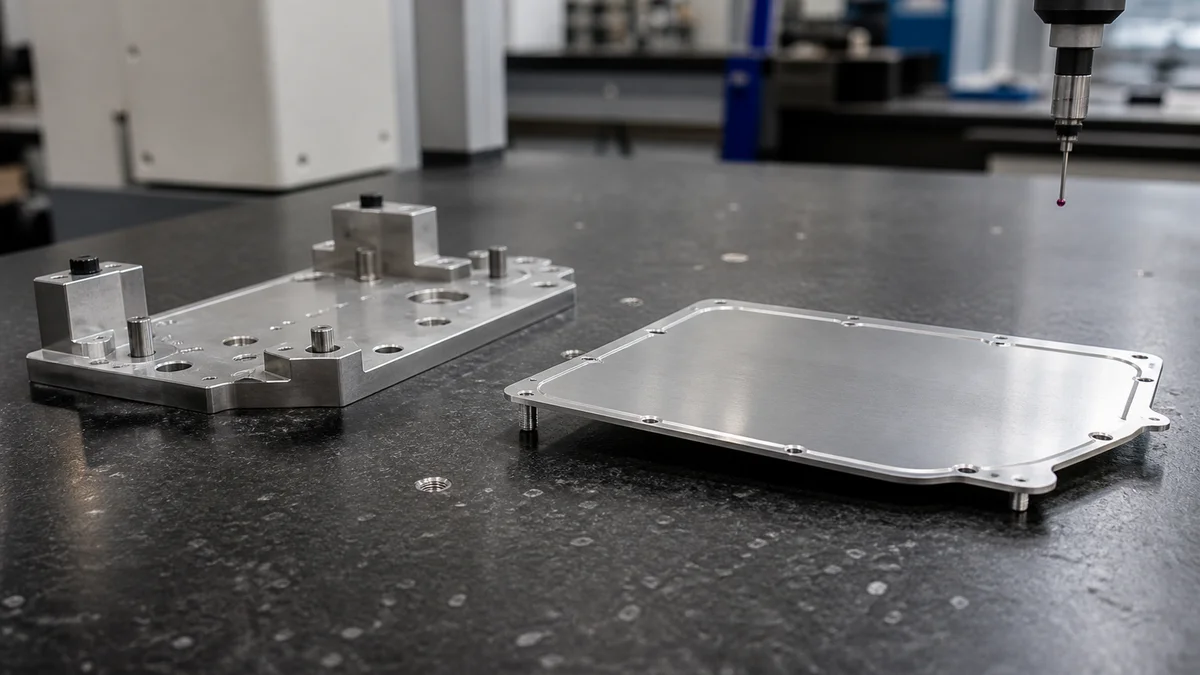
Workholding can conceal distortion. A flexible machined plate pulled against a fixture may appear flat during cutting but recover after the clamps are released. This is not sheet-metal springback caused by bending; it is elastic recovery8 or dimensional movement related to clamping, stiffness, and internal stress in a machined component.
Residual stress may exist in the starting stock and become apparent as material is removed. Deep pockets, thin walls, one-sided cutting, and asymmetric sections change the balance of the part. Heat treatment, coating preparation, grinding, lapping, or later machining can introduce or reveal additional movement.
Scenario: A thin machined cover is inspected while firmly supported on a surface plate and recorded as acceptable. The buyer later measures it with a different support arrangement and obtains another result. Neither result settles acceptance unless the drawing defines whether the cover is measured free, supported at specified points, or restrained to represent assembly.
Temperature can also matter across large spans or when tolerances are demanding. If machining, inspection, and service environments differ, state the applicable reference temperature or stabilization expectation rather than leaving the measurement condition open.
Define four items to prevent disputes:
- The manufacturing stage at which the control applies
- Whether the part is free or restrained
- How its support or datum is established
- When final inspection occurs relative to heat treatment and finishing
The machining and inspection plans can then evaluate the part in its delivered or assembled condition instead of relying on a temporary fixture state.
What Drives the Cost and Lead Time of Flatness and Parallelism?
Cost and lead time increase when geometric controls require more stable stock, specialized workholding, staged machining, stress relief, secondary finishing, controlled measurement, repeated inspection, or additional documentation. The complete manufacturing and verification route matters more than cutting time alone.

Flatness and parallelism affect quotation through interacting material, geometry, machining, finishing, and inspection decisions. The same tolerance on a compact block and a broad thin plate can require very different process plans.
| Cost or schedule driver | Manufacturing effect | RFQ input that reduces uncertainty |
|---|---|---|
| Material grade, condition, and stock form | Stability and machinability influence the route | Exact material specification and permitted alternatives |
| Part envelope and minimum wall thickness | Stiffness affects clamping and movement | Complete 3D model and section details |
| Pocket layout and removed material | Unbalanced cutting may release stress | Finished geometry and critical-face identification |
| Datum relationships and setup count | Reclamping can introduce transfer error | Functional datums and cross-face controls |
| Heat treatment or finishing | Later operations may alter geometry | Complete process sequence and acceptance stage |
| Grinding or lapping | Adds routing, handling, and verification | Localized form and finish requirements |
| Inspection frequency and reporting | Measurement and documentation use production capacity | Sampling plan, required evidence, and report scope |
Quantity and production stage affect how these costs are distributed. A one-off prototype may use simpler workholding and concentrated final inspection. Repeat-production planning9 may justify developed fixtures, stable in-process checks, and an agreed sampling plan. Neither route should be assumed without realistic lot information.
Undefined requirements create delay and contingency. A missing datum, an unclear support condition, conflicting model and drawing data, or an unresolved post-treatment requirement can stop process planning.
Compare quotations using the same controlled package. Each quotation should identify its assumed stock, principal machining stages, secondary operations, inspection scope, and whether the delivery schedule includes outside processing and final reporting. This gives a more useful comparison than machine rate or unit price alone.
Which Manufacturing Process Does the Specification Apply To?
Confirm the manufacturing process before applying flatness or parallelism guidance because machining, punching, stamping, fabrication, and molding create geometry differently. Their tooling, material form, distortion risks, datum strategies, and final inspection conditions are not interchangeable.
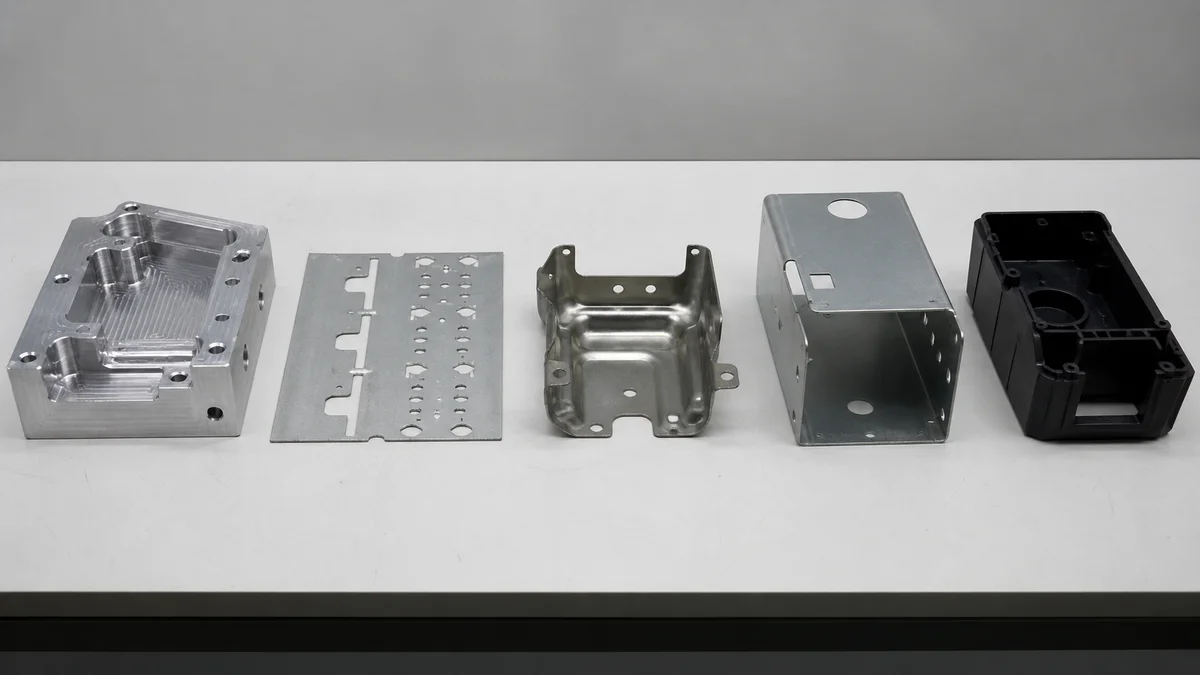
This article concerns CNC machining, where cutting tools remove material from solid stock through milling, turning, drilling, boring, reaming, or related operations. In this context, flatness and parallelism depend on stock condition, material removal, workholding, tool access, setup relationships, and later processing.
| Process | Material and operating method | Relevant geometric risks |
|---|---|---|
| CNC machining | Removes material from bar, plate, billet, or other stock | Clamping deformation, residual-stress movement, setup transfer, finish allowance |
| CNC turret punching | Uses programmed punch tools on sheet metal | Sheet support, local distortion, burr direction, and later forming |
| Metal stamping | Cuts or forms sheet metal with dedicated dies | Die condition, forming sequence, springback, and repeat stability |
| Sheet metal fabrication | May combine cutting, punching, bending, welding, hardware, and finishing | Bend accumulation, springback, weld distortion, and assembly condition |
| Plastic injection molding10 | Forms polymer inside a mold | Shrinkage, warpage, wall thickness, draft, gate location, and cooling conditions |
A flatness requirement on a machined plate should not be evaluated as though it were a post-bend sheet-metal dimension. Likewise, a molded plastic housing involves flow, shrinkage, cooling, draft, gate location, and wall-thickness effects that do not describe machining from solid stock.
“CNC turret punching, CNC punch press, CNC-controlled stamping equipment, or metal stamping depending on the actual process” is not one standard process term. It may be used informally for CNC turret punching, CNC punch-press work, CNC-controlled stamping equipment, or general die stamping. The RFQ should clarify the intended process, material form, geometry, quantity, and production stage.
When a fabricated, stamped, cast, or molded component receives secondary CNC machining, identify which operation creates each datum and which final condition governs inspection. A hybrid route can be appropriate, but the drawing must separate the requirements assigned to each manufacturing stage.
What Should a Flatness and Parallelism RFQ Include?
A flatness-ready RFQ should define the complete part, functional surfaces, governing drawing rules, material condition, geometric controls, final manufacturing state, inspection evidence, quantity, revision, and delivery expectations. Complete inputs allow competing quotations to address the same manufacturing and acceptance requirement.
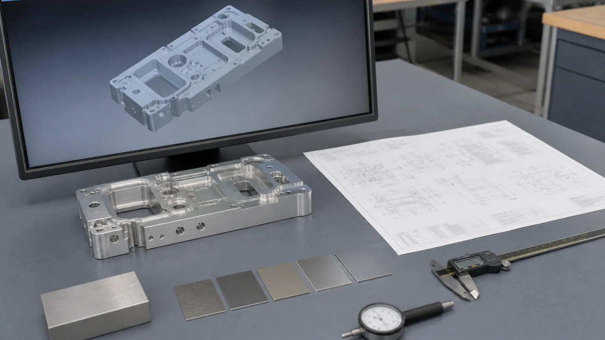
Send both a complete 3D model and a controlled 2D drawing. The model supports geometry, stock, tool-access, and manufacturability review. The drawing controls units, datums, GD&T, tolerances, finish, notes, inspection requirements, and revision. If the files conflict, identify the governing document before quotation.
RFQ and approval checklist
- ☐ Complete 3D CAD model
- ☐ Controlled 2D drawing with part number, units, and active revision
- ☐ Governing GD&T standard and revision11
- ☐ Exact material grade, temper, condition, and relevant stock restrictions
- ☐ Immediate quantity and projected lot or annual demand when known
- ☐ Prototype, validation, pilot, or repeat-production intent
- ☐ Functional, assembly-related, cosmetic, and non-critical surfaces identified
- ☐ Critical tolerance values and units clearly stated
- ☐ Datum features and datum sequence defined for parallelism
- ☐ Mating-function explanation for demanding flatness or parallelism controls
- ☐ Thin walls, broad faces, deep or one-sided pockets, and flexible regions highlighted
- ☐ Surface-finish requirements localized to applicable faces
- ☐ Heat treatment, anodizing, coating, grinding, lapping, and other secondary operations listed
- ☐ Dimensions and geometric controls identified as pre-finish or final-condition requirements
- ☐ Free-state or restrained inspection condition defined where relevant
- ☐ Temperature or stabilization expectations stated when they affect acceptance
- ☐ First-article, sampling, per-lot, or selected 100 percent inspection scope defined
- ☐ Required reports, actual-value records, and approval evidence listed
- ☐ Delivery expectations, partial-shipment needs, and approval timing included
- ☐ Permission for design-for-manufacturability alternatives stated
Before award, obtain written confirmation of the datum interpretation, proposed process route, final inspection stage, sampling scope, and report contents. This approval step exposes differences in stock, workholding, secondary finishing, measurement, and schedule assumptions while revisions remain manageable.
For a manufacturing review or quotation, submit the 3D model, controlled 2D drawing, material grade and condition, quantity, prototype or production intent, critical tolerances, datums, surface finish, inspection expectations, active revision, and delivery requirements. Include the mating function and final measurement condition for every demanding flatness or parallelism control.
References
-
Parallelism (GD&T) Explained - ASME Y14.5-2009 divides tolerances in GD&T into 14 different types. are form, profile, orientation, location and runout. control the flatness ... ↩
-
A Dimension and Tolerance Data Model - The data structures provide a link between tolerances and geometric entities used in geometric modeling and a common interface between geometric modelers and ... ↩
-
Datum Feature - Datums are theoretically exact points, axes, lines, and planes. A datum feature is the tangible surface or feature of size. ASME Y14.5 – 2009 ↩
-
Effects of Aluminum Plate Initial Residual Stress on ... - The findings from simulations and experiments show that inherent residual stress alone could distort a high-aspect-ratio part beyond aerospace industry ... ↩
-
Overcoming Residual Stresses and Machining Distortion in ... - by MS Younger · 2007 · Cited by 42 — Reducing this level of disturbance is more critical to minimizing machining distortion than is reducing residual stress magnitude, per se. ↩
-
Mastering Flatness Measurement: Techniques and Tools ... - Flatness measures how closely all surface points lie within two parallel planes; that gap between the planes is the flatness value. A datum ... ↩
-
How GD&T Should Influence Your Manufacturing and ... - GD&T is intended to communicate the functional requirements of the part, while eliminating tight tolerances from non-critical features. ↩
-
Free and Clamped State Inspection in One Go - With Mapvision Virtual Clamp, get both the free state and clamped measurement during the same inspection cycle of welded car parts. ↩
-
Prototype to Production Guide | NPI, FAI & Scale-Up | Mockup - Mockup helps product teams move from CAD review and DFM through manufacturing, inspection and repeat production. apply before requesting a quote. ↩
-
Injection Molding: The Causes of Warpage - This shows polypropylene tensile bar shrinkage without glass fiber in two gate locations: end of the part (left) and center of the part ... ↩
-
Y14.5 - Dimensioning and Tolerancing - It establishes symbols, rules, definitions, requirements, defaults, and recommended practices for stating and interpreting GD&T and related requirements for use ... ↩