

Metal stamping tolerances should describe how the finished part must fit, locate, and function—not demand maximum precision everywhere. Pierced holes, blanked edges, bends, formed surfaces, and long feature spans respond differently to die clearance, material flow, springback, and accumulated variation. Ignoring those differences can produce expensive tooling while leaving the most important assembly relationships unclear.
A stronger specification classifies features, establishes functional datums, and reserves close controls for characteristics that affect assembly or performance. Material grade, sheet thickness, process route, production intent, and inspection scope must support those requirements.
The following decisions turn general tolerance notes into a stamping-ready specification that suppliers can evaluate consistently for tooling, production, inspection, cost, and schedule.
Which Manufacturing Process Are You Actually Specifying?
Identify the intended manufacturing route before assigning tolerances because metal stamping, CNC turret punching, sheet metal fabrication, CNC machining, and plastic injection molding create geometry through different mechanisms. If an RFQ says “CNC turret punching, CNC punch press, CNC-controlled stamping equipment, or metal stamping depending on the actual process,” replace that ambiguous term with the specific operation the part actually requires.

Metal stamping cuts or forms sheet metal with dedicated dies. Progressive die stamping is a specific route in which strip material advances through fixed stations that may pierce, trim, bend, coin, or form the part. Station relationships, strip control, material flow, and tool condition can all influence the finished geometry.
A CNC turret punch press works differently. It uses programmed hits from physical punch tools to make holes, cutouts, and certain localized forms in sheet. Broader sheet metal fabrication may combine turret punching or laser cutting with bending, hardware insertion, welding, finishing, and secondary machining.
CNC machining removes material from solid stock through milling, turning, drilling, boring, or reaming. Plastic injection molding forms polymer in a mold and introduces separate considerations such as wall thickness, draft, gate location, shrinkage, and cooling. Neither should be presented as interchangeable with stamping.
| Process | How geometry is created | Primary tolerance influences |
|---|---|---|
| Metal stamping | Dedicated dies cut or form sheet | Die construction, material flow, springback, tool condition |
| Progressive die stamping | Strip advances through sequenced die stations | Strip location, station relationships, accumulated forming effects |
| CNC turret punching | Programmed punch tools act on sheet | Tool availability, hit sequence, sheet support, feature spacing |
| Sheet metal fabrication | Cutting, bending, joining, and finishing are combined | Bend sequence, joining, secondary operations, final assembly condition |
| CNC machining | Cutters remove material from solid stock | Workholding, tool access, setup relationships |
| Plastic injection molding | Molten polymer fills and cools in a mold | Shrinkage, cooling, draft, gates, warpage |
“CNC turret punching, CNC punch press, CNC-controlled stamping equipment, or metal stamping depending on the actual process” is not a standard process definition. It might refer to turret punching, CNC punch press work, CNC-controlled stamping equipment, or general die stamping. Resolve that ambiguity before suppliers interpret the tolerances or choose tooling.
Which Stamped Features Need Separate Tolerances?
Specify stamped-part tolerances by feature class rather than applying one blanket limit. Pierced-hole size, hole position, edge distance, bend angle, bend location, overall length, and flatness respond to different cutting and forming variables, so each critical characteristic needs an appropriate acceptance requirement.
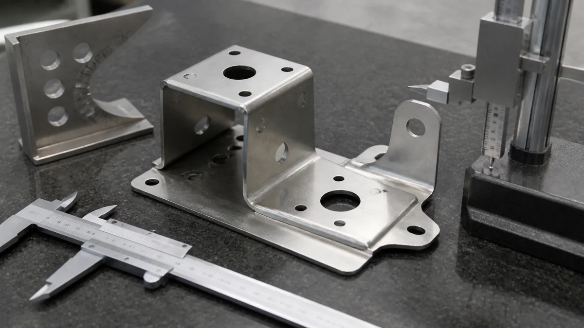
Cutting and forming events do not affect every dimension in the same way. Pierced-hole diameter is influenced by the punch, die opening, material, and tool condition. Hole position also depends on how the strip or blank locates. Bend angle responds to springback, while a bend-to-hole dimension combines piercing location with forming variation.
| Feature class | What should be specified | Practical consequence |
|---|---|---|
| Pierced-hole diameter | Finished size limits and required edge condition | Controls fastener or pin clearance without defining location |
| Hole or pattern location | Position from functional datums | Protects assembly alignment independently of hole size |
| Edge-to-hole distance | Reference convention and tolerance | Prevents ambiguity between center-to-edge and boundary-to-edge dimensions |
| Bend angle | Controlled faces and angular tolerance | Makes springback compensation and inspection meaningful |
| Bend-to-hole or bend-to-edge | Final formed relationship | Captures combined cutting and forming variation |
| Overall length | Finished envelope and applicable stage | Avoids treating a long noncritical span like a local interface |
| Flatness | Exact controlled area and measurement condition | Prevents a local mounting need from becoming a whole-part requirement |
Use a general tolerance note for ordinary geometry only when it matches the material, part size, intended stamping route, and supplier practice. Apply explicit controls to assembly-driving holes, locating edges, formed interfaces, mounting zones, and burr-sensitive features.
Common specification mistake: placing the same close plus-or-minus limit on every dimension. This can over-control clearance edges while leaving an assembly-critical pattern poorly related to its locating surfaces. A feature-based tolerance plan1 instead shows what governs fit, which datums establish location, and whether acceptance applies after forming, deburring, and finishing.
When Does a Tight Tolerance Require a Different Stamping Route?
Escalate the manufacturing route only when a critical feature cannot be controlled adequately by conventional blanking or forming. Progressive dies, fine blanking, trimming, coining, and restriking address different problems, and each can change tooling design, process steps, inspection effort, cost, and launch timing.
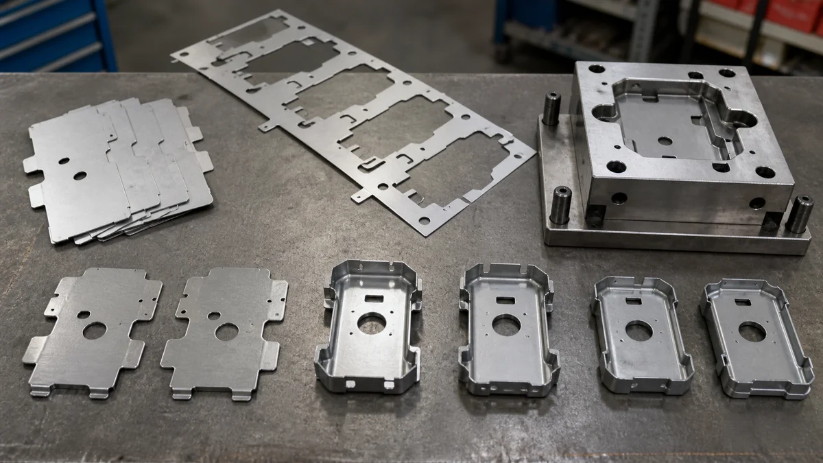
A tight drawing limit is not automatically a reason to specify a more elaborate process. First define the functional result: hole location, cut-edge condition, formed angle, local geometry, or flatness. The supplier can then assess whether ordinary stamping is suitable or whether another die operation or secondary process is justified.
| Route or operation | Condition it may address | Effect on the manufacturing plan |
|---|---|---|
| Conventional blanking or forming | Ordinary cut and formed features | Establishes the baseline die and inspection approach |
| Progressive die stamping | Stable repeat demand with sequenced operations | Requires dedicated stations, strip planning, tryout, and approval |
| Fine blanking | Selected critical edges or precision features | Changes die strategy and demands closer process review |
| Dedicated trimming | Final control of a specific edge or profile | Adds an operation, handling, and inspection |
| Coining | Local material displacement or selected correction | Changes tooling loads and local material behavior |
| Restriking | Stabilization of selected formed geometry | Adds a die station or secondary forming step |
Process fit remains conditional on material grade, sheet thickness, geometry, quantity, tolerance, burr direction, edge requirements, and inspection level. One demanding interface may justify a localized trim or restrike without forcing every feature through the most demanding route.
Example: A bracket has ordinary outside edges but one mating edge that locates an assembly. Instead of specifying fine blanking for the complete profile, identify that edge, its datum relationship, permitted burr direction, and final inspection requirement. The supplier can compare conventional blanking followed by a dedicated trim with other feasible routes.
Avoid using fine blanking, coining, or restriking as general quality labels. State the delivered requirement and allow the supplier to propose the simplest capable route unless engineering has a documented reason to control the operation.
How Should Material and Springback Affect Formed-Feature Tolerances?
Set formed-feature tolerances from the specified material, thickness, bend radius, grain direction, and functional reference surfaces. Springback occurs when sheet partially recovers after the forming load is removed, so identical bend callouts may require different compensation and control across different materials and conditions.
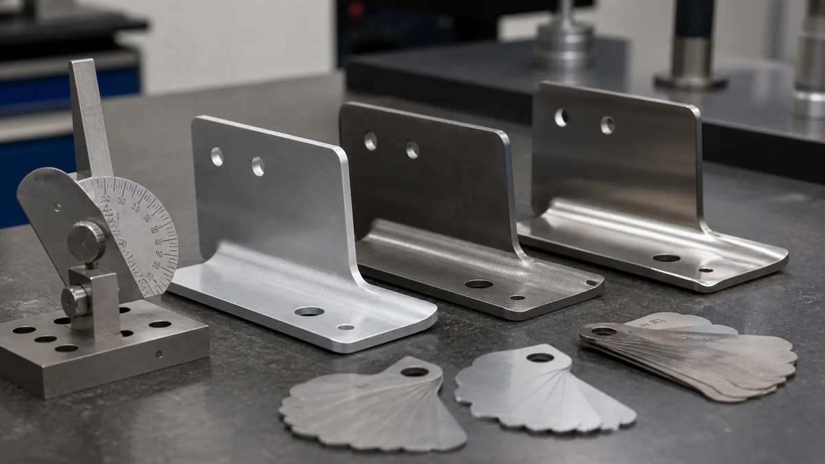
Springback changes the final angle and location of a formed feature after it leaves the die. Its effect depends on material response, geometry, and tooling—not merely the nominal CAD angle. Mild steel, stainless steel, aluminum, and high-strength sheet should not be assumed to behave identically under the same callout.
Before releasing the drawing, define:
- The exact material grade, temper, or condition rather than only “steel” or “aluminum.”
- Nominal sheet thickness and any requirement governing thickness variation.
- Grain direction when it affects forming or part performance.
- Inside bend radius and the face, edge, or datum controlling the feature.
- Whether function depends on bend angle, flange location, hole position after forming, or a mating-surface relationship.
- Whether dimensions apply before or after coating, deburring, and final forming operations.
A nominal angle alone may not protect assembly. If a flange locates another component, controlling that completed interface from functional datums is often more useful than chaining dimensions from convenient blank edges. The drawing should also identify whether the inside or outside formed surface establishes the dimensional reference.
Scenario: A stainless bracket and an aluminum bracket share the same nominal shape, but one flange locates a sensor. Giving both parts an identical bend note without reviewing material recovery and tool-wear risk creates a false equivalence. Control the sensor-mounting relationship in the finished condition, then let each supplier review compensation, forming sequence, tooling, and inspection for the specified material.
Do not prescribe unsupported springback compensation values. Provide the material and functional geometry, and require sample or first-article approval when the formed relationship needs confirmation before repeat production.
How Should You Control Long Spans and Tolerance Stack-Up?
Control long stamped parts from functional datums and evaluate the complete assembly stack rather than tightening every chained dimension. Hole-to-hole, bend-to-hole, bend-to-bend, and overall spans accumulate variation differently, so longer noncritical dimensions may need more freedom than local mating relationships.
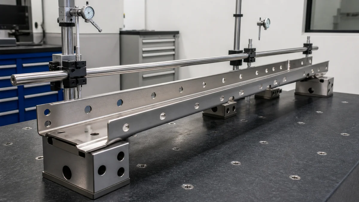
Tolerance stack-up2 is the combined variation created when several dimensions or manufacturing events determine one final relationship. In a stamped component, that chain may include blank location, piercing, multiple bends, restriking, and final trimming. Every individual dimension can pass while the completed assembly relationship still fails.
Baseline or datum-based dimensioning usually communicates intent more clearly than a long chain of edge-to-feature dimensions. Select references that represent how the part locates in the assembly. Locate critical holes, mating edges, and formed interfaces from those references. The overall envelope can remain controlled without becoming the origin for every functional feature.
Which relationships deserve a stack-up review?
Review dimensions that cross multiple operations or connect directly to another component. Typical candidates include hole patterns spanning a long part, holes located across a bend, opposing flanges, and mounting points separated by several formed features. A short clearance slot does not normally carry the same risk as a relationship spanning the complete component.
Scenario: A channel-shaped bracket has mounting holes on opposing flanges. Each flange width and bend angle passes separately, but chained dimensions from one blank edge allow the final hole spacing to exceed the assembly clearance. A stronger specification establishes a functional datum on the mounting interface and controls the completed hole relationship from that datum after forming.
Avoid redundant dimensions that define the same feature twice. Mark reference dimensions clearly, identify the requirement governing acceptance, and state that assembly-driving relationships are inspected on the completed part. Longer noncritical spans can retain process-appropriate limits while local mating relationships receive closer, directly inspectable control.
Where Should Flatness and Other Critical Controls Apply?
Apply flatness, position, bend-location, and edge controls only where they protect mounting, sealing, locating, or mating functions. Blanket precision across a stamped part can require extra die development, coining, restriking, secondary processing, handling, and inspection without improving how the component assembles or performs.

Flatness controls the form of one surface3, not its orientation to another datum. In a stamped part, final surface form can be affected by residual stress, material flow, multiple forming stages, springback, handling, and finishing. A broad panel may also produce different readings depending on how it is supported during inspection.
Before applying flatness, determine:
- Which exact surface or local zone contacts another component.
- Whether acceptance applies in a free state or a defined restrained condition.
- Whether the requirement must be met after stamping, restriking, deburring, coating, and every secondary operation.
- Which inspection condition represents the delivered or assembled part.
Localize other close controls in the same way. Position belongs on locating or fastener patterns that affect assembly. Bend location needs close control when a flange establishes a functional interface. A cut edge may need a specific location, edge condition, or burr direction when it controls clearance, sealing, or handling. Cosmetic and noncontact regions can generally remain under process-appropriate general requirements.
Common specification mistake: applying a tight whole-part flatness requirement because one small mounting zone must sit securely. That callout can lead suppliers to consider broader coining, restriking, added handling, secondary flattening, or extensive inspection on surfaces that never touch the assembly. A localized mounting control related to functional datums may express the need more directly.
Ask suppliers to review demanding controls against the finished geometry, material grade, thickness, forming sequence, surface finish, quantity, and measurement condition. The objective is a specification that protects fit and function without assigning precision to irrelevant areas.
What Inspection Plan Should Accompany Critical Stamping Tolerances?
Pair every critical stamping tolerance with a defined datum structure, final measurement condition, inspection frequency, and reporting expectation. Hole size, hole position, bend angle, and flatness are different characteristics; specify the acceptance evidence and let the supplier propose a suitable repeatable measurement method.

Inspection scope affects quotation, tooling approval, and production planning. A supplier cannot price a close tolerance consistently if it is unclear whether the buyer expects first-article results, routine sampling, final dimensional records, or inspection of every selected feature.
| Characteristic | Acceptance question | Information required in the RFQ |
|---|---|---|
| Hole size | Does the finished opening meet its size limits? | Nominal size, limits, feature identity, frequency |
| Hole position | Is the hole correctly located from functional datums? | Datum scheme, controlled pattern, reporting scope |
| Bend angle | Is the final orientation acceptable? | Reference faces, final condition, sample plan |
| Bend-to-hole location | Is the relationship correct after forming? | Governing datums and post-form requirement |
| Flatness | Does the selected surface meet its form limit? | Controlled area, support condition, final process stage |
| Edge or burr condition | Is the delivered edge acceptable? | Burr direction, protected edges, measured or visual criterion |
Do not prescribe one inspection technology for every characteristic without a functional reason. An accessible independent size may suit a direct gauge. A datum-related hole pattern or formed relationship may need a coordinate-based method or a functional checking fixture. Define the characteristic and acceptance basis first, then let the supplier propose a repeatable inspection method.
The RFQ should state whether initial sample approval releases production, whether sampling continues during repeat lots, and whether drawing revisions or tooling changes trigger renewed review. First-article inspection4 demonstrates that the inspected samples meet the controlled revision; it does not by itself prove ongoing capability.
Where documented evidence matters, require actual measured values rather than only pass or fail. Reports should identify the part, revision, characteristic, nominal requirement, tolerance limits, result, and acceptance status.
What Should a Stamping-Ready RFQ Include?
A stamping-ready RFQ must combine controlled geometry, exact material information, production demand, critical tolerances, finish, inspection, revision, and delivery requirements. It should also classify cutting and forming features, identify permitted alternatives, and resolve which document governs if the 3D model and drawing disagree.
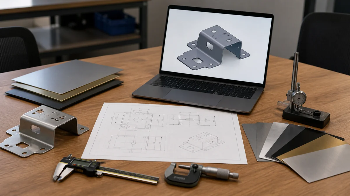
The RFQ should give every supplier the same manufacturing and acceptance basis. A 3D model communicates the finished geometry; the controlled 2D drawing communicates tolerances, datums, notes, units, feature classifications, inspection requirements, and revision status. Neither file should silently contradict the other.
Use this complete RFQ approval checklist5:
- Current 3D CAD model showing the complete finished geometry.
- Controlled 2D drawing with part number, units, active revision, and applicable general tolerances.
- Statement identifying which document governs if the model and drawing conflict.
- Exact material grade, temper or condition where relevant, nominal thickness, and grain-direction requirement.
- Immediate quantity, prototype, pilot, or production intent, and expected repeat demand when known.
- Critical-to-function dimensions, functional datums, geometric controls, and ordinary noncritical tolerances.
- Identification of pierced, blanked, bent, coined, trimmed, restrained, welded, or otherwise processed features when that distinction affects acceptance.
- Bend references, final formed dimensions, flatness zones, burr direction, edge requirements, and protected surfaces.
- Surface finish, coating, masking, cosmetic zones, and whether dimensions apply before or after finishing.
- Inspection scope covering first articles, production sampling, selected full inspection, report content, and final measurement condition.
- Required material or process documentation only where the purchase requirement calls for it.
- Delivery expectations, partial-shipment needs, packaging constraints, and approval timing.
- Permission—or prohibition—for alternative tooling routes, secondary operations, or design-for-manufacturability changes.
Common RFQ mistake: requesting production pricing from an evolving model without a controlled drawing, demand context, or inspection plan. Suppliers then make different assumptions about tooling commitment, revisions, secondary operations, and acceptance evidence. The resulting quotations describe different scopes and cannot be compared reliably.
For a process recommendation, sample plan, or quotation, send the current 3D model and controlled 2D drawing with material grade, sheet thickness, quantity, prototype or production intent, critical tolerances, surface finish, inspection expectations, revision level, and delivery requirements. Identify the features that drive assembly and whether alternative stamping routes or secondary operations are permitted.
References
-
Metal Stamping Design Guide: Material, Tolerances & ... - 6.0Precision Hole Location Tolerances ; Same-plane piercing is extremely accurate: ±.002″ between holes is common. ; Tightly spaced holes may ... ↩
-
GD&T: Geometric Dimensioning & Tolerancing Guide [2026] - Tolerance stack-up analysis determines whether an assembly will function given the combined variation of all contributing dimensions. ↩
-
GD&T Symbol - Flatness | ASME Y14.5 Symbols - One way to improve the form of the surface is to add a flatness tolerance. Flatness is often used to: control the primary datum feature to improve ... ↩
-
What are First Article Inspections? - It documents every characteristic on the engineering drawing with nominal values, tolerances, and actual measured results, creating a traceable record ↩
-
Metal Stamping Parts RFQ Checklist - Send a 2D drawing with dimensions, tolerances and notes, plus a 3D CAD file or flat pattern if available. Also include material, thickness, quantity, finish, ... ↩