
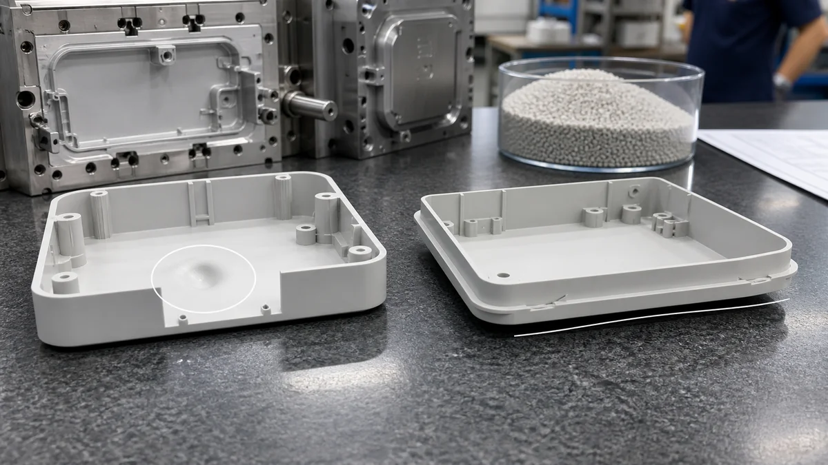
Sink marks and warpage often begin with the same physical problem: different regions of an injection-molded part shrink and cool at different rates. A sink mark is a localized surface depression, usually associated with concentrated material. Warpage occurs when unequal contraction or residual stress pulls the part away from its intended shape.
Neither defect is reliably controlled through one machine setting. Wall thickness, ribs, bosses, resin behavior, gates, packing, cooling, venting, ejection, tolerances, and cosmetic requirements form one connected molding system. Reviewing them separately can move the defect without resolving its cause.
The practical goal is to translate requests for a flat, dimensionally stable, visually acceptable part into geometry, tooling, process, and inspection requirements that a molder can evaluate before tool release.
How Should Wall Thickness Be Designed to Reduce Sink Marks and Warpage?
Keep nominal walls as uniform as practical, core out unnecessary heavy sections, and use gradual transitions where thickness must change. This reduces differences in filling, packing, shrinkage, and cooling that can create visible sink marks, residual stress, or dimensional warpage.
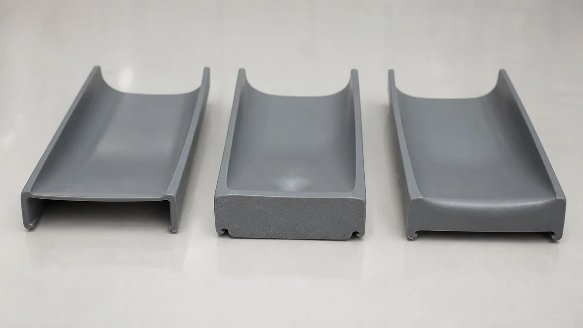
A sink mark forms when the interior of a thick region continues shrinking after its exterior has started to solidify. Warpage is a broader shape change caused by unequal shrinkage, cooling, or locked-in stress. Both may begin with wall-thickness variation, but they require different acceptance criteria.
Prepare a wall map before mold quotation. Mark the nominal wall, thick-to-thin transitions, internal corners, boss and rib junctions, cosmetic faces, and assembly interfaces. Core out a heavy section when it has no functional purpose. If loading or assembly requires a thickness change, use a gradual transition and suitable radius instead of an abrupt step. Resin-specific wall-thickness design guidance1 should inform this review because one nominal wall does not suit every polymer or flow length.
| Geometry condition | Manufacturing risk | Drawing or DFM response |
|---|---|---|
| Consistent nominal wall | More uniform shrinkage and cooling | Identify the intended nominal wall |
| Abrupt thickness step | Local cooling difference and residual stress | Use a gradual transition where practical |
| Solid heavy region | Sink, internal shrinkage, and extended cooling | Core the region or revise the load path |
| Thick feature behind a visible face | Depression or visible read-through | Mark the cosmetic zone for DFM review |
| Large flat panel | Assembly-related warpage | Define functional datums and measurable acceptance |
Common specification mistake: Thickening the entire wall to strengthen one local area. This adds material without necessarily supporting the real load path. Curvature, ribs, gussets, or a different resin may provide stiffness with less concentrated mass, subject to structural and molding review.
How Should Ribs and Bosses Add Stiffness Without Causing Sink?
Use controlled ribs, gussets, and cored bosses to carry loads without creating hidden masses of resin. Review their thickness, height, spacing, root radius, draft, and relationship to cosmetic faces together instead of specifying each feature independently.
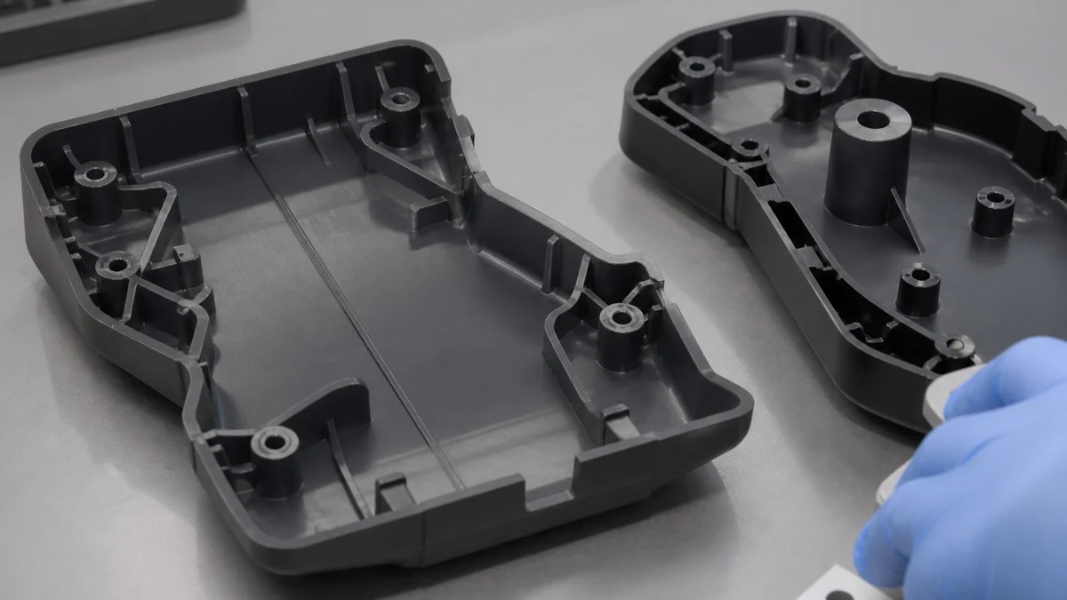
Ribs should reinforce a defined load path, not behave as thick extensions of the main wall. The supported rib thickness reference of about 50–60% of the adjoining wall is useful for DFM review, but it is not a universal moldability guarantee. Resin grade, flow length, rib height, spacing, root geometry, draft, gate location, and surface requirements remain part of the decision.
Review each reinforcing feature for:
- its structural or assembly purpose;
- thickness relative to the adjoining nominal wall;
- height and spacing in relation to filling and ejection;
- root radius and draft direction;
- proximity to a critical cosmetic surface;
- whether several smaller ribs could replace one heavy rib;
- whether it restricts cooling, venting, or a mold action.
Bosses need the same discipline. A fastening boss should generally be reviewed as a cored feature, with ribs or gussets transferring assembly load into the surrounding structure. A solid cylinder attached directly to a thin wall concentrates resin and may create sink or print-through on the opposite face. When an insert is required, specify its type, installation method, load direction, and relevant boss geometry. Resin supplier rib design recommendations2 can provide useful material-specific context without replacing toolmaker review.
Scenario: Injection molded cover DFM. A teaching example uses a cover with thick fastening bosses behind a visible exterior and uneven walls around its mounting points. Before tooling, the review covers boss coring, rib connections, wall transitions, draft, gate access, and cosmetic acceptance. The aim is to remove avoidable mass and expose the remaining risk—not to promise a defect-free result.
How Should Gate Design and Packing Be Coordinated?
Place and size gates so packing pressure can reach shrinkage-prone regions before gate freeze. Establish useful hold time through a gate freeze study or stable part-weight observation, then adjust packing pressure and duration in controlled steps.
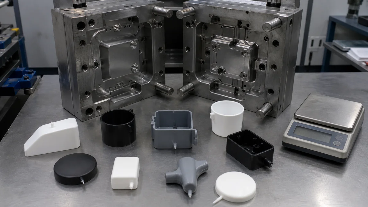
Packing adds material after initial cavity filling to compensate for volumetric shrinkage. It works only while the gate can transfer pressure into the cavity. Once the gate freezes, extending hold time cannot feed more material into the affected region. Sink should therefore not be treated simply as a request for higher pressure.
Gate location should support thicker or more shrinkage-sensitive areas without creating unacceptable flow marks, weld lines, or cosmetic effects. Gate size must keep the pressure path open for the intended packing phase. A large or complex part may need multiple gates for balanced filling, but additional gates can introduce weld-line and appearance concerns. Resin, flow length, wall distribution, cosmetic zones, and mold layout all influence the choice.
How can useful hold time be established?
A gate freeze study changes hold duration in controlled steps while monitoring whether part weight continues to increase. Stable part weight can indicate that additional hold time is no longer transferring material. Gate freeze study methodology3 should be applied within a documented process-development plan so other variables do not obscure the result.
Example: A thick boss sits far from a small gate, yet the troubleshooting instruction says only “increase holding pressure.” If that gate freezes before pressure reaches the boss effectively, additional pressure or time may not solve the problem. Review the boss mass, gate location, gate size, flow path, cooling, and nearby cosmetic surface together. This diagnostic sequence prevents machine settings from being used indefinitely to compensate for a part-design or tooling constraint.
When Should Cooling Uniformity Take Priority Over a Shorter Cycle?
Prioritize cooling uniformity whenever temperature differences can affect flatness, shrinkage, cosmetic surfaces, or ejection stability. A shorter cycle is not useful if thick regions remain hot, the part distorts after release, or residual stress appears later.
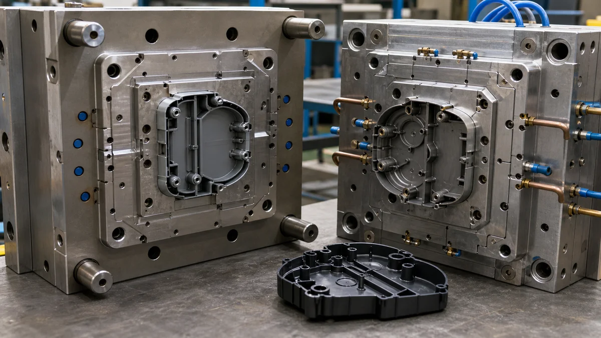
Cooling time is only one part of cooling control. The mold must remove heat uniformly enough for critical regions to reach a suitable ejection condition at the intended stage of the cycle. A thick section may remain hot after an adjacent thin wall has solidified, giving the two regions different shrinkage histories.
Review the cooling-channel layout against the wall map, gates, bosses, ribs, inserts, core features, and large flat surfaces. Mold-temperature control must also fit the selected resin. Extending the cycle may reduce premature ejection, but it cannot correct channels that consistently leave one side or feature hotter than another. Credible mold cooling design principles4 are useful when evaluating whether channel placement supports the actual heat load.
| Cooling control | Specification question | Practical consequence |
|---|---|---|
| Channel layout | Are thick and critical regions cooled with reasonable balance? | Tool design complexity and temperature variation |
| Mold temperature | Does the proposed range fit the resin and geometry? | Flow, crystallinity, surface condition, and shrinkage |
| Cooling duration | Is the part sufficiently solid before release? | Cycle time and ejection stability |
| Ejection timing | Can the part resist release and ejector forces? | Distortion and witness-mark risk |
| Inspection timing | Does shape change after further cooling? | Measurement condition and sample approval |
Cycle reduction should follow a stable acceptance process. If a part appears flat immediately after ejection but changes later, specify when and how it will be inspected. Cooling engineering and validation may add tooling effort or launch work, but those drivers should be compared with the recurring cost and quality risk of an unstable cycle.
How Should Resin Selection Change the Molding Process Window?
Build the molding process window around the exact resin grade, additives, moisture condition, shrinkage behavior, and crystallinity. Do not transfer drying, melt-temperature, packing, or mold-temperature settings from another polymer merely because the part geometry is unchanged.

A material family name is not enough for tooling or process review. The RFQ should identify the exact resin grade, reinforcement or other additives, color, approved alternatives, and required conditioning. These inputs affect flow, shrinkage, cooling, surface appearance, and dimensional behavior.
PA66 is moisture-sensitive, so its drying condition belongs in the process plan and approval record rather than remaining an unstated shop assumption. PEEK may require high mold temperatures to manage crystallinity; its mold-temperature strategy cannot simply be copied from a lower-temperature resin. These examples do not establish universal settings. They show why official resin processing guidance5 and molder review should support the proposed process window.
| Resin factor | RFQ or approval question | Sink or warpage implication |
|---|---|---|
| Exact grade and additives | Which material will production use? | Flow and shrinkage may change |
| Moisture condition | Is drying or conditioning defined? | Processing stability and dimensions may vary |
| Crystallinity | Does mold temperature need special control? | Cooling rate and shrinkage can be affected |
| Melt temperature | Can the cavity fill without excessive thermal input? | Packing, weld lines, and finish interact |
| Approved alternative | What requires revalidation after substitution? | The original process window may not remain valid |
Lowering melt temperature can reduce total volumetric shrinkage in some situations, but it is not a universal correction. Excessive reduction may impair filling, weld-line quality, or surface appearance. Tune melt temperature with packing pressure, hold time, cooling, gate behavior, and actual flow length. A proposed material substitution after tooling should trigger a documented review of the affected process and acceptance characteristics.
How Can Balanced Flow and Venting Reduce Warpage Risk?
Use balanced runners and gates to limit unequal filling and packing, and place effective vents near credible end-of-fill or trapped-air regions. Review these features with mold actions and ejection because flow balance alone cannot correct an obstructed or asymmetric mold layout.
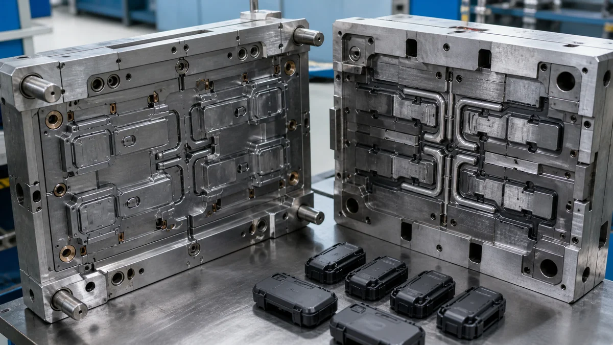
Warpage can begin during filling when different regions experience different flow, pressure, orientation, or packing histories. A balanced runner and gate arrangement aims to fill comparable regions under comparable conditions. Venting gives displaced air a controlled escape path, reducing localized short packing, compressed air, and uneven pressure distribution.
Before tool release, review:
- the predicted fill sequence and end-of-fill regions;
- runner balance and the pressure path to each cavity or feature;
- gate locations relative to thick sections and cosmetic faces;
- vent locations near credible air traps;
- weld-line locations that could affect function or appearance;
- interference from parting lines, shutoffs, sliders, lifters, and core pins;
- ejection forces and the risk of asymmetric release;
- cooling around heavily packed or flow-sensitive areas.
Mold-flow analysis can support this work for a large, multi-gated, appearance-critical, or dimension-critical part. Its value depends on inputs that represent the intended resin, wall map, gates, runners, cooling arrangement, and process assumptions. Mold flow analysis inputs6 based on an obsolete resin or preliminary gate layout should not be treated as approval evidence for the released tool.
Example: A broad housing fills from one side and has a distant rib network behind a flat assembly face. Review whether the fill pattern, end-of-fill venting, gate pressure path, rib geometry, cooling, and ejection layout load the two sides differently. The appropriate correction may involve geometry, gates, runners, vents, cooling, or ejection rather than one isolated machine adjustment.
How Should Sink, Warpage, and Dimensional Acceptance Be Specified?
Define sink, warpage, and dimensional acceptance through identified surfaces, functional datums, measurable limits, inspection conditions, cavity tracking, and sample approval. Avoid blanket tolerances or vague cosmetic language that leaves the supplier to guess when a molded part is acceptable.
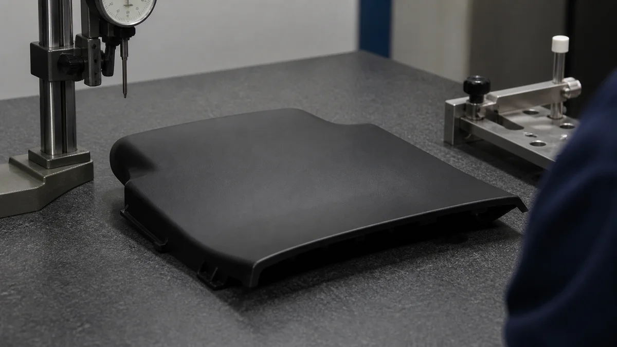
Acceptance should reflect how the part fits, seals, locates, and appears in service. Separate critical assembly interfaces from clearance geometry and hidden surfaces. If flatness, profile, or another feature relationship controls function, select datums that represent how the part is located during assembly and inspection. This avoids replacing a real functional requirement with a blanket dimensional tolerance.
Cosmetic sink requirements also need defined zones and viewing conditions. A note such as “no sink marks” does not say which faces are visible, how they will be judged, or whether minor variation on a hidden surface matters. An approved limit sample or written cosmetic standard may provide a clearer basis for acceptance. Cosmetic inspection conditions7 should identify the surface, viewing arrangement, and approval route.
| Acceptance characteristic | Required specification information | Approval evidence |
|---|---|---|
| Critical dimension | Nominal value, tolerance, datum relationship, measurement condition | Recorded dimensional result |
| Warpage or profile | Controlled surface, datum setup, limit, inspection timing | Defined measurement report |
| Cosmetic sink | Visible zone, viewing condition, comparison basis | Approved sample or cosmetic record |
| Cavity variation | Cavity identification and reporting method | Results traceable by cavity |
| Initial samples | Quantity, tests, revision, approval authority | Signed or recorded disposition |
| Repeat production | Frequency, sampling scope, required records | Ongoing inspection evidence |
Scenario: A cover must sit on a frame without rocking while its exterior remains visible. Control the mounting interface from functional datums and identify the exterior as a cosmetic zone. State whether inspection occurs free-standing or under defined restraint, and specify when the part is measured after molding.
For appearance-critical or dimension-critical parts, structured process development or DOE may be justified. Agree before quotation which variables, samples, reports, and ongoing controls are required.
What Should a Mold-Ready Injection Molding RFQ Include?
A mold-ready RFQ should define the current geometry, exact resin, demand, tooling expectations, critical tolerances, cosmetic zones, inspection scope, sample approval, revision, and delivery requirements. Complete inputs allow the supplier to evaluate sink, warpage, mold complexity, and validation risk before quotation.
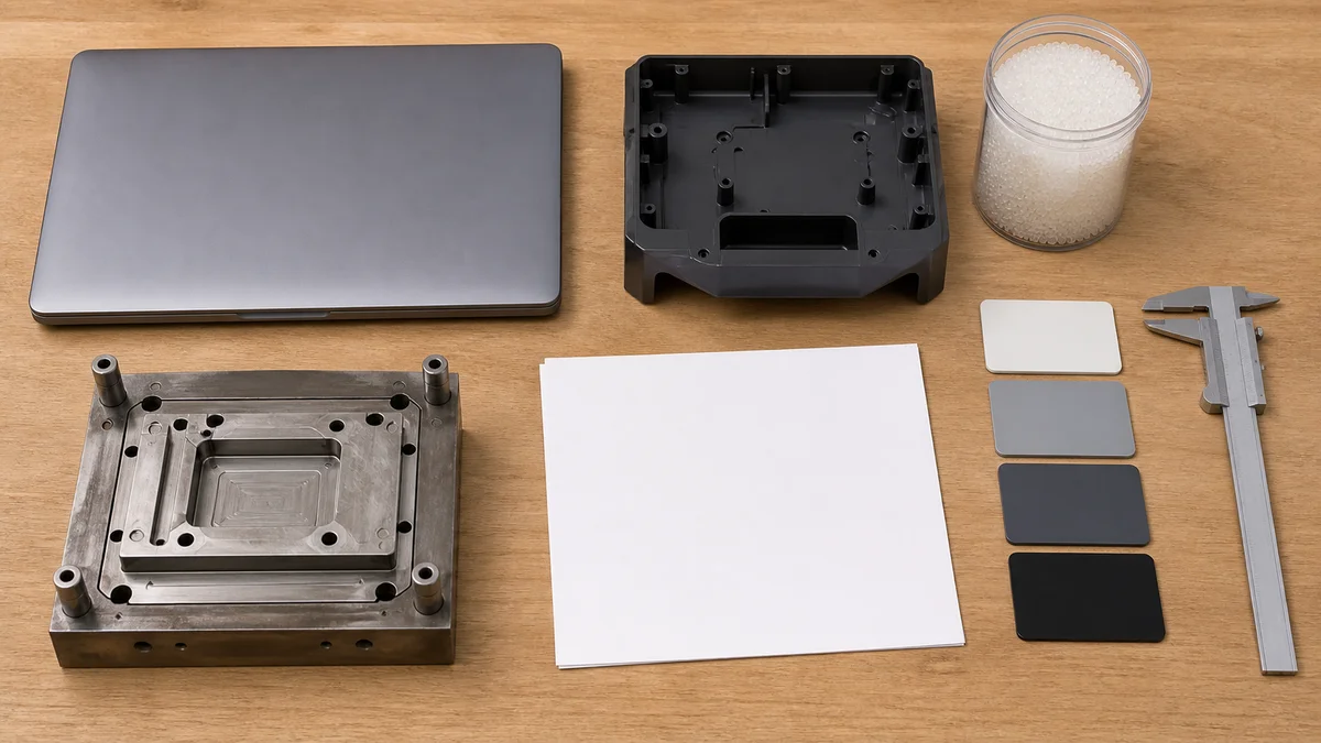
Send both a 3D model and a controlled 2D drawing. The model communicates complete geometry; the drawing controls specifications, datums, tolerances, cosmetic zones, revision, and inspection requirements. If they conflict, identify the governing document and resolve the mismatch before tooling begins.
A complete mold-ready RFQ checklist8 should include:
- current 3D model and controlled 2D drawing;
- active part number and revision level;
- exact resin grade, additives, color, and approved alternatives;
- nominal wall map and identified heavy sections;
- purpose and geometry of ribs, bosses, gussets, and inserts;
- draft, texture, and surface-finish expectations;
- preferred or restricted gate and parting-line locations;
- undercuts, sliders, lifters, shutoffs, and pull directions;
- functional datums, critical tolerances, and warpage criteria;
- cosmetic zones and sink-mark acceptance method;
- immediate quantity, annual demand, and prototype or production intent;
- tooling ownership and expected validation scope;
- sample tests, cavity identification, inspection frequency, and reports;
- packaging, delivery expectations, and permitted DFM alternatives.
Name the process correctly. Plastic injection molding fills a mold with polymer. CNC machining removes material from solid stock. CNC turret punching and CNC punch press work use programmed punches on sheet metal. Metal stamping cuts or forms sheet with dedicated dies. Sheet metal fabrication may combine cutting, punching, bending, welding, and finishing. CNC-controlled stamping equipment may describe automation applied to stamping, but “CNC turret punching, CNC punch press, CNC-controlled stamping equipment, or metal stamping depending on the actual process” is not one standard process term. An RFQ using it must clarify the intended operation.
Incomplete demand, revision, inspection, or approval information can change tooling assumptions, validation effort, cost, and schedule even when the CAD geometry appears complete.
For a DFM recommendation, sample plan, or quotation, send the current 3D model and controlled 2D drawing with the exact resin grade, quantity, prototype or production intent, critical tolerances, surface finish and cosmetic zones, inspection expectations, revision level, tooling scope, and delivery target.
References
-
Injection Molding Wall Thickness Guidelines - Walls in any plastic-molded part should be no less than 40 to 60 percent that of adjacent walls, and all should fit within recommended thickness ranges for the ... ↩
-
Plastic Rib and Boss Design: Sizing and Sink Prevention - A common rule of thumb is that rib thickness in injection molding should not exceed 60% of the nominal wall thickness. Keeping ribs thinner helps promote even ... ↩
-
INJECTION MOLDING: Gate Freeze Study: Danger in a ... - The test actually determines the hold time needed to mold repeatable parts, and it should be done regardless of whether the gate freezes or not. ↩
-
The Importance of Cooling Lines in Injection Molding - Cooling lines, or cooling channels, support the uniform cooling of injection molds and the production of plastic parts that are free from sink ... ↩
-
Complete Guide to PEEK Injection Molding Parameters ... - PEEK typically processes within a barrel temperature range of 350-400°C (662-752°F), though specific grades may require adjustments. ↩
-
Mold Flow Analysis in Injection Molding - By analyzing potential gate locations, mold flow analysis software can suggest where to put gates so the mold fills evenly and completely. A mold flow analysis ... ↩
-
Cosmetic Specifications for Injection Molded Parts - VIEWING Dripping or sagging of paint or ink … held based upon limit sample 30 deg. INSPECTION OF PLASTIC mark SPECKS. VIEWING CONDITION A. ANGLE All viewing ... ↩
-
Plastic Injection Molding RFQ Checklist for Quote-Ready ... - Use this plastic injection molding RFQ checklist to align CAD, 2D drawings, resin grade, CTQ dimensions, tolerance notes, tooling assumptions, validation scope, ... ↩