
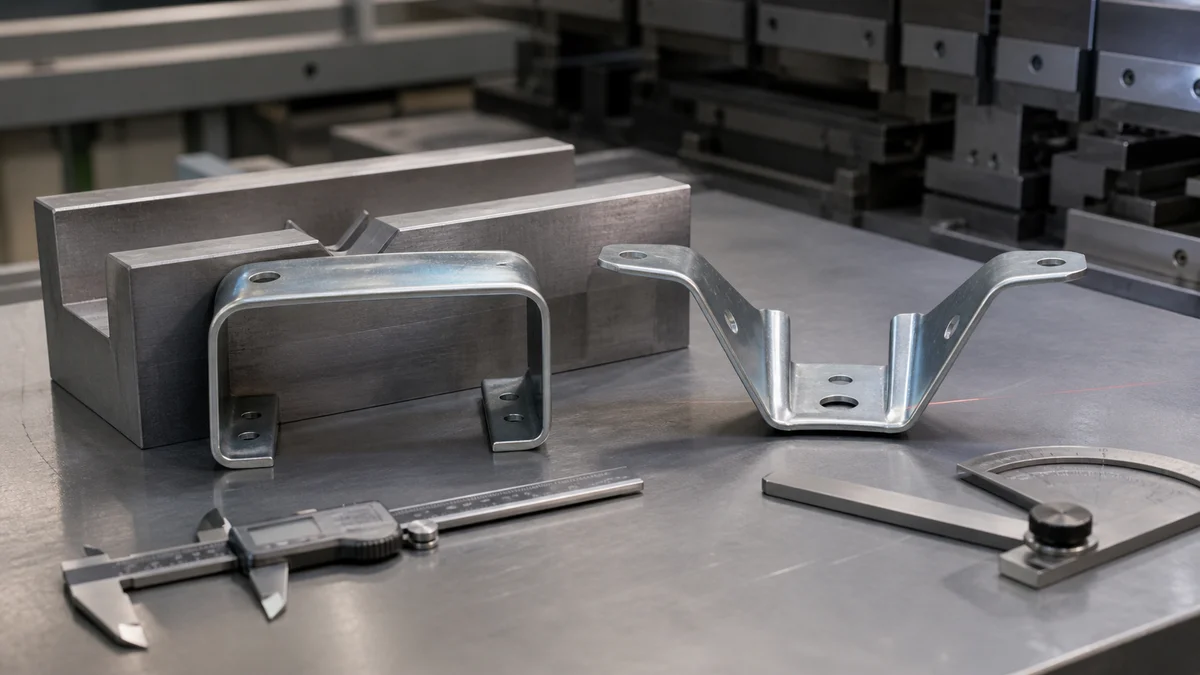
Springback occurs when sheet metal elastically recovers after the forming load is removed. A bend can open, a flange can shift, a sidewall can curl, or an entire profile can move away from the tool shape. Tightening every drawing tolerance or assigning one standard overbend angle will not control these different responses.
Effective springback control connects the forming mode with material grade, condition, thickness, grain direction, part geometry, die design, process stability, and inspection state. Depending on the actual failure mechanism, the practical response may be overbending, localized coining, compensated die geometry, controlled draw-in, staged forming, or a different production route.
The following decisions help engineering and procurement teams diagnose the recovery mechanism, choose proportionate countermeasures, and give a stamping supplier enough specification evidence to develop and validate the process.
What Causes Springback, and Which Forming Mode Is Being Used?
Springback is elastic recovery after forming pressure is removed. Before selecting a countermeasure, classify the operation as simple bending, flanging, drawing, or draw-bending because each mode creates a different stress distribution and can shift angles, radii, sidewalls, or the complete part profile.
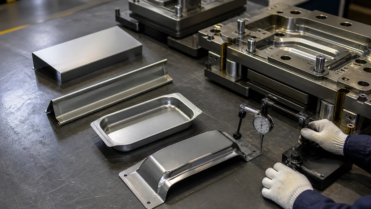
A formed sheet contains permanent plastic strain and recoverable elastic strain. When the die opens, the elastic portion relaxes. The visible result may be an opened bend angle, a changed radius, sidewall curl, twist, or profile loss across a drawn panel.
The forming mode indicates where recovery is likely to appear and which controls deserve attention:
| Forming mode | Typical released-part change | Specification and process inputs to review |
|---|---|---|
| Simple bend | Bend angle opens | Grade, thickness, grain direction, inside radius, overbend |
| Flanging | Flange angle or edge position moves | Flange length, local stiffness, overbend, coining |
| Drawing | Walls, corners, or overall profile move | Blank holder force, draw beads, lubrication, blank position |
| Draw-bending | Angle change and sidewall curl occur together | Draw-in, residual stress, die compensation, forming sequence |
Correct process terminology matters. Metal stamping uses dedicated dies to cut or form sheet metal, and progressive stamping moves strip through a fixed sequence of die stations. CNC turret punching or CNC punch press work uses programmed tools to create sheet features. Broader sheet metal fabrication may include cutting, bending, punching, welding, and finishing. CNC machining removes material from solid stock, while plastic injection molding forms polymers in a mold.
“CNC turret punching, CNC punch press, CNC-controlled stamping equipment, or metal stamping depending on the actual process” is not a standard process name. If it appears in an RFQ, clarify whether it means CNC turret punching, CNC punch press work, CNC-controlled stamping equipment, or dedicated-die metal stamping1. Otherwise, suppliers may evaluate springback against the wrong forming route.
Which Material Variables Must Be Fixed Before Compensating for Springback?
Fix the material grade, strength condition, temper, sheet thickness, grain direction, and permitted substitutions before developing springback compensation. Higher-strength sheet generally recovers more after release, while changes in condition or thickness can invalidate an overbend, draw-in setting, or compensated die developed for another material.
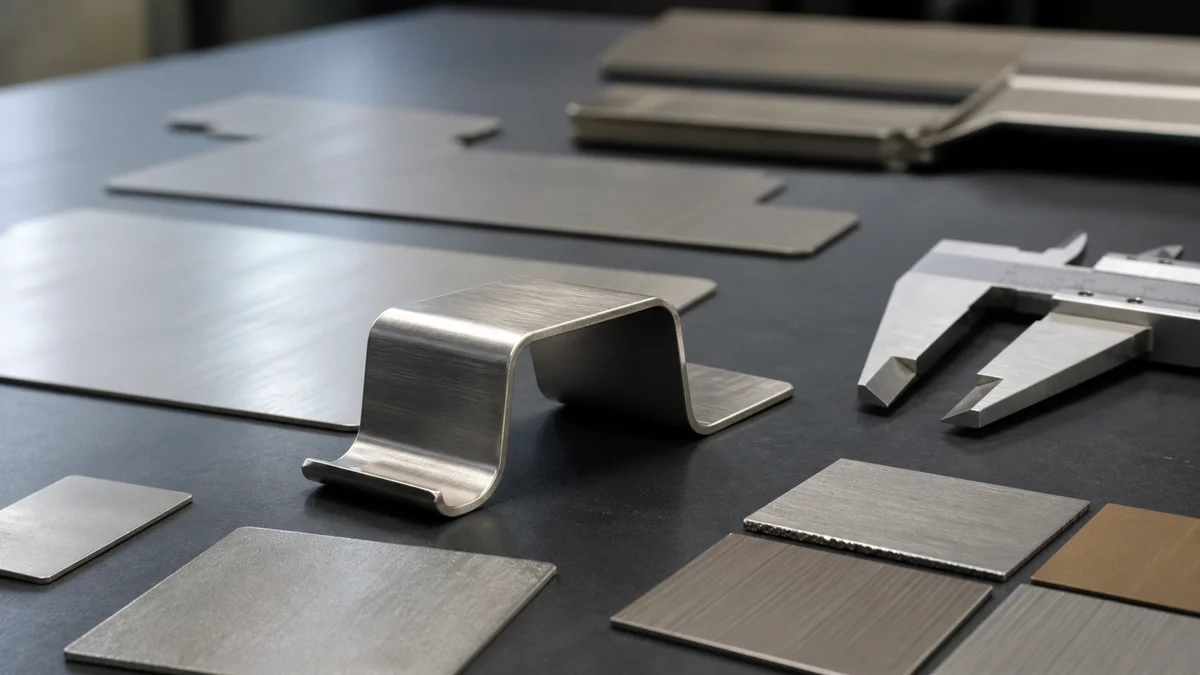
A broad material name such as “steel” or “aluminum” is insufficient. Springback follows the sheet’s elastic and plastic response, so the controlled specification should establish:
- Exact material grade and applicable supplied condition.
- Temper, annealed state, pre-tempered state, or other strength condition where relevant.
- Nominal sheet thickness and any applicable thickness requirements.
- Grain direction when bend orientation or anisotropic behavior affects the result.
- Approved alternatives and who may authorize a substitution.
- Required material-lot documentation or verification.
Higher yield strength generally means greater elastic recovery2. Cold-rolled steel, stainless steel, aluminum, and advanced high-strength steel should therefore not be expected to use identical compensation on similar geometry. An annealed or lower-yield-strength condition may reduce rebound if it still satisfies structural and service requirements, but material should not be weakened simply to make forming easier.
Scenario: A stamped stainless steel clip has a critical connector interface. Burr direction, bend radius, springback, material hardness, and grain orientation affect assembly more directly than a generic overall tolerance. If the die is developed for one stainless condition and a harder condition is later introduced, the released angle can change even though the CAD geometry and nominal thickness remain the same. This is a teaching scenario, not a customer case.
A common specification mistake is allowing an undefined “equivalent material.” Any alternative must preserve the properties governing both part function and forming behavior. Review it before carrying established overbend, draw-in, or die-compensation settings into production.
When Is Overbending the Right Springback Compensation Method?
Overbending is suitable when recovery is predictable, material and production conditions are stable, and the tooling can move beyond the required final angle without interference or damage. The die intentionally passes the target so the released feature returns toward its specified angle.
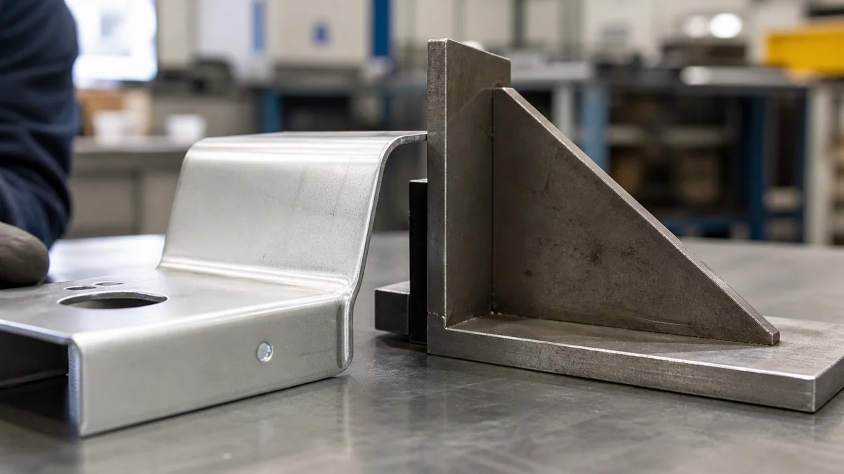
Overbending compensates for springback rather than removing its physical cause. The tool forms a bend or flange beyond the drawing requirement; elastic recovery then brings the released feature toward its target angle.
This is often the most direct starting point for a simple bend or flange. It becomes less reliable when complex draw-in, changing sidewall stress, abrupt geometry transitions, or inconsistent material behavior controls the result. The correction must be developed for the actual grade, condition, thickness, grain direction, bend radius, flange length, and production setup.
What must remain stable for overbending to work?
Material sourcing and lot behavior must remain representative of the approved condition. Blank orientation, tool condition, lubrication, and part location can also affect released geometry. Define the final bend angle from clear reference surfaces and a functional datum; the tooling angle is a process input, not the delivered-part acceptance requirement.
Example: A flange locates a mating panel after release. The supplier may form it beyond the final angle and inspect its relaxed position from the assembly datum. If a later material lot has a different strength condition, applying the original springback compensation3 without confirmation may leave the flange overclosed or overopened.
Two specification mistakes recur. One is treating a single overbend value as universal across material lots, tempers, thicknesses, or grain directions. The other is approving a part while it is restrained even though the drawing requires free-state acceptance. Validate the correction under the same material, tooling, and measurement conditions intended for production.
When Should Coining Be Used to Hold a Critical Bend?
Use coining or staking selectively when a critical bend needs stronger local springback control than predictable overbending can provide. High compressive pressure plastically deforms the bend zone, but it also increases forming load, tooling stress, and the risk of changing the radius or visible surface.
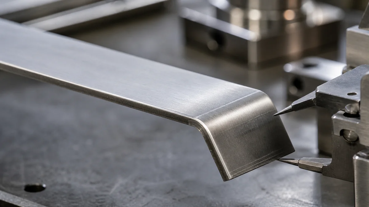
Coining concentrates high compressive force at or near the bend radius. The added plastic deformation reduces the stored elastic energy available to reopen the bend. It may suit a localized feature whose released angle directly controls assembly, alignment, or electrical contact.
It is not a routine quality upgrade. Suitability depends on material strength, thickness, bend radius, tool support, available forming load, surface restrictions, and how much local deformation the design can accept.
| Decision factor | Overbending | Coining or staking |
|---|---|---|
| Operating principle | Forms beyond target, then allows recovery | Compresses the bend zone to reduce recovery |
| Practical fit | Predictable simple bends and flanges | Local critical bends needing stronger control |
| Tooling concern | Travel and geometric clearance | Higher load and concentrated tooling stress |
| Geometry effect | Primarily changes forming angle | Can alter local radius or material condition |
| Surface risk | Ordinary forming contact | Localized witness marks or surface change |
| Inspection focus | Released angle and flange position | Released angle, radius, local profile, and surface |
Specify the final angle, inside radius, surface condition, and datum relationship. Unless a governing requirement mandates the method, describe the delivered result rather than demanding coining. The supplier can then compare coining with overbending, restriking, or staged forming.
Common mistake: A blanket note calls for coined bends throughout the part even though only one flange controls assembly. This increases forming load, tool development, and inspection while potentially changing noncritical radii. Localize critical bend control4 and state whether tool witness marks are acceptable.
When Does the Die Need Springback Compensation?
Compensate the die when complex or tightly controlled stamped geometry cannot be corrected reliably by a simple overbend or localized operation. The tool surface is modified opposite the expected recovery, but effective compensation requires stable material data, blank control, lubrication, draw-in, and forming conditions.
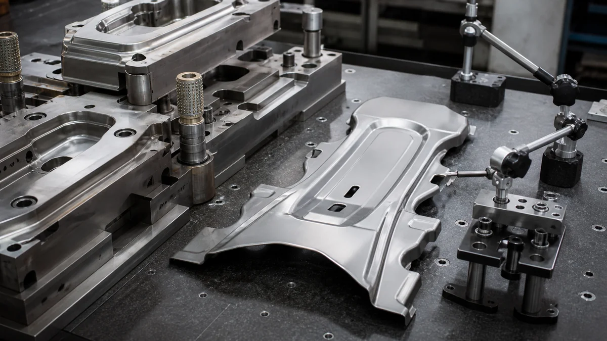
Die compensation changes the tool surface so the released part—not the closed-tool shape—approaches the drawing requirement. On a complex panel or multi-feature stamping, compensated geometry may counter predicted twist, angular recovery, wall movement, or profile deviation across several regions.
Finite-element analysis5 can indicate the direction and relative character of springback before tryout. It does not replace representative inputs or physical validation. A die corrected from one unrepresentative material condition can still drift when production variation appears.
Stabilize and document these inputs before approving permanent correction:
- Material grade, strength condition, thickness, grain direction, and representative property data.
- Blank shape, orientation, position, and repeatable locating method.
- Blank holder force plus any pressure profile or timing affecting draw-in.
- Draw-bead geometry and intended flow restriction.
- Lubrication type, coverage, and application consistency.
- Tool movement, forming sequence, and any restrike station.
- Critical profiles, angles, radii, datums, and inspection state.
Focus correction on functional geometry controlling fit, sealing, alignment, or assembly. Applying close profile requirements to every surface can expand tool development and inspection without protecting the product’s function.
A disciplined approval sequence compares predicted recovery with measured free-state parts, adjusts the die where the evidence supports correction, and confirms the result across the agreed process window. Premature tool changes create a repair loop: each modification responds to a moving process instead of a repeatable recovery pattern.
How Should Draw-In and Residual Stress Be Controlled?
Control draw-in by coordinating blank holder force, draw beads, pressure location and timing, lubrication, and blank position. These inputs determine how material enters the die and how residual stress is distributed, which can govern sidewall curl and profile movement in drawn or draw-bend parts.
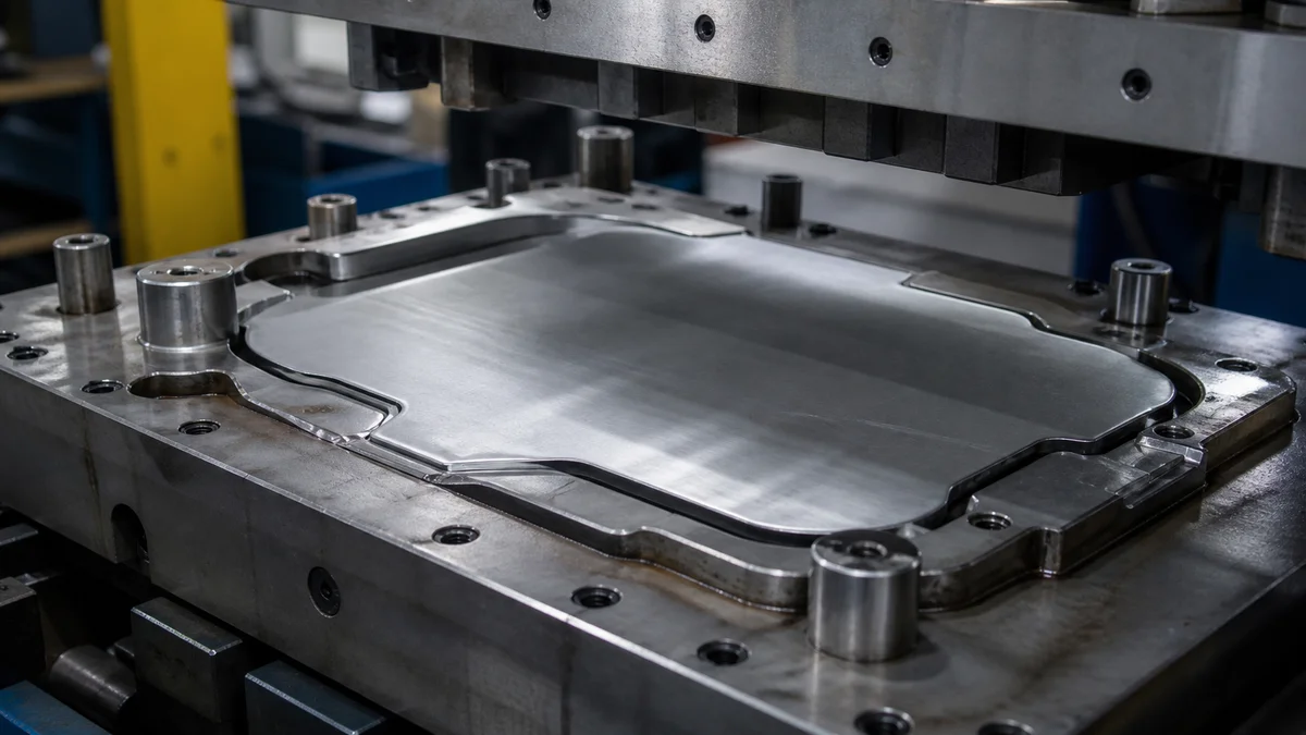
Draw-in is the movement of sheet from the binder region into the forming cavity. Excessive, insufficient, or uneven movement changes strain distribution, wall shape, and residual stress after release. On a drawn component, controlling punch travel alone may not control the finished profile.
Blank holder force restrains flow, but its location and timing can matter as much as its nominal magnitude. Draw beads introduce selected resistance along particular paths. Lubrication changes friction at the tool-sheet interface, while blank position determines whether the intended material volume reaches each region.
Specify the delivered geometry and critical relationships, then preserve enough supplier freedom to tune the forming process. Prescribing an unsupported holder force or lubricant setting can prevent the process engineer from balancing draw-in for the actual die, material, and production setup.
Which drawing information supports draw-in control?
Identify critical wall profiles, trim edges, flange positions, radii, cosmetic surfaces, and assembly datums. State whether each feature is bent, drawn, or produced through a draw-bend sequence. Mark any surface that cannot accept bead witness, pressure marking, or a local texture change.
Scenario: A shallow drawn cover meets its edge dimensions but its wall moves after release. Increasing overbend at one flange may not address the stress distribution. Blank position, draw-bead restraint, holder-force balance, and lubrication consistency deserve review because material flow across the whole part drives the failure.
Unstable draw-in can overwhelm accurate compensated tooling. Establish a repeatable material-flow condition before making permanent die-surface correction the primary remedy.
Should the Part Geometry or Forming Sequence Be Changed?
Change the geometry or forming sequence when one severe operation creates unstable recovery or the released part lacks enough stiffness to retain shape. Pre-bending, staged forming, ribs, revised flange lengths, and smoother transitions may reduce springback, but each option must preserve function, material flow, and appearance.
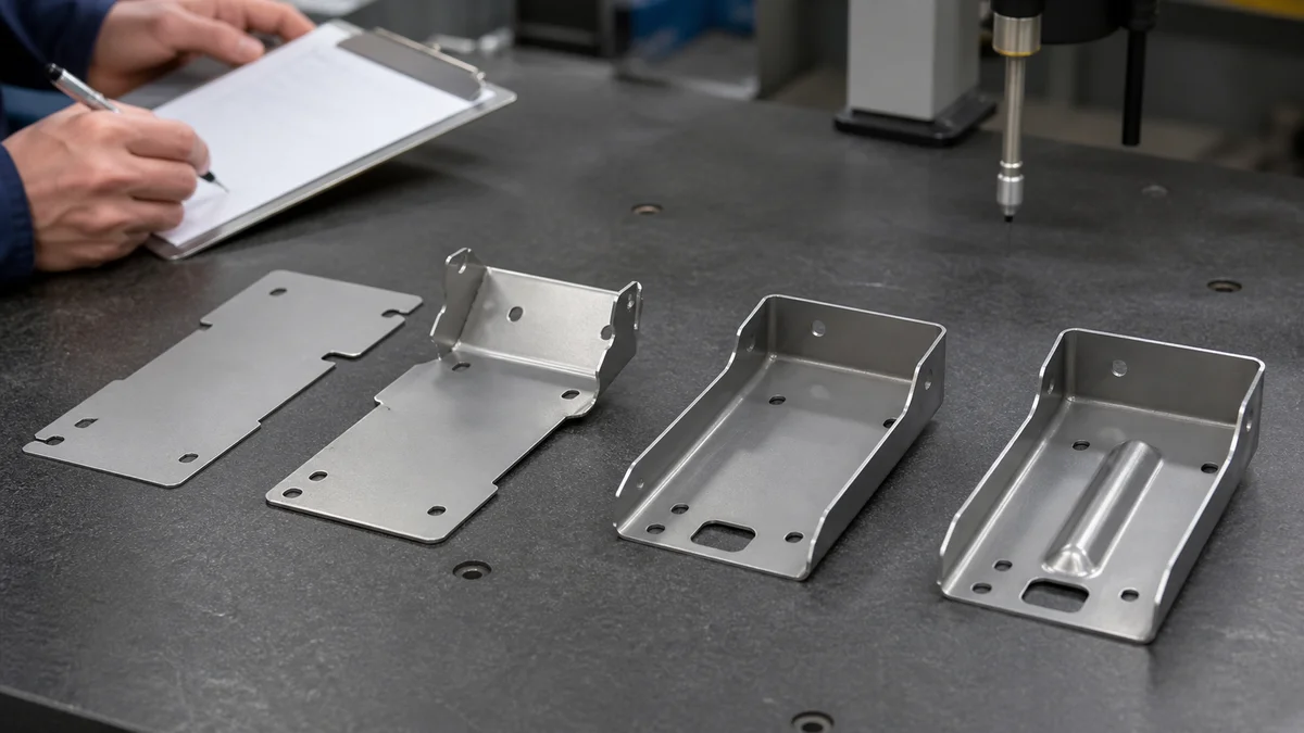
A tooling adjustment cannot always overcome geometry that concentrates strain or leaves a long feature flexible after release. Before fixing the die concept, compare a targeted part revision with the extra stations and tryout work required for staged forming.
| Option | Intended effect | Specification or tooling tradeoff |
|---|---|---|
| Pre-bending | Introduce strain before final forming | Adds sequence dependency and tool development |
| Multiple forming stages | Distribute deformation across operations | Adds stations, handling, tryout, and inspection |
| Rib or stiffener | Increase released-part rigidity | Changes material flow, clearance, and appearance |
| Revised flange length | Reduce leverage or improve forming control | Can affect assembly reach and mating geometry |
| Smoother section transition | Reduce abrupt strain concentration | May conflict with packaging or interfaces |
| Revised die-radius flow path | Change the residual-stress pattern | Can require blank and die redesign |
First establish which geometry is functionally fixed. A rib is unsuitable if it interferes with a mating component. A larger transition radius may improve forming but remove required clearance. Conversely, a cosmetic contour with no assembly function can be a sensible revision if it eliminates difficult compensation.
A long return flange that repeatedly opens could be addressed through greater overbend, a localized stiffening feature, a revised flange length, or two-stage forming. Compare the options using final fit, tool access, visible surfaces, die complexity, inspection, tryout effort, quantity, and production intent—not angle control alone.
The RFQ should mark fixed interfaces and identify where design-for-manufacturability alternatives6 are permitted. Suppliers can then quote the controlled design and a revised option without assuming authority to change functional geometry.
When Does Sidewall Curl Require Post-Forming Tension?
Post-forming tension may be appropriate when a drawn wall or panel curls after release because residual stress varies through the sheet thickness. Post-stretching, stake beads, hybrid beads, or active binder-force control can redistribute that stress when ordinary angular overbend does not address the distortion mechanism.
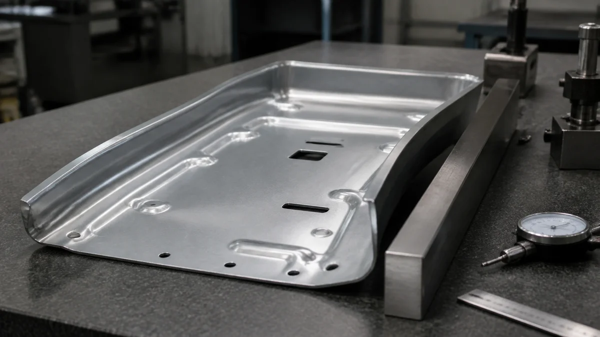
Sidewall curl is more than an incorrect bend angle. It develops when the stress distribution through the material thickness makes a wall or panel curve after release. A long wall may therefore fail its profile even when adjacent radii and flange angles meet their individual requirements.
That distinction changes the remedy. Increasing overbend at one edge can move a local angle without correcting the stress gradient responsible for wall curvature. Post-stretching or in-plane tension can alter the elastic strain state across the affected region. Stake beads, hybrid beads, and active binder-force control are possible methods when the forming sequence and available access support them.
What should a sidewall-curl review include?
Provide the full released geometry rather than isolated bend callouts. Mark the affected wall, curl direction, functional datums, assembly contact regions, and surfaces where gripping, beads, or pressure marks are prohibited. Include material grade, condition, thickness, grain direction, blank orientation, and the current forming sequence.
Inspection needs an equally clear state. A wall restrained against a fixture may appear acceptable while the free part remains curled. If assembly restraint is intentionally part of the design, define the fixture or assembled condition and its locating scheme. Otherwise, specify a free-state profile or another measurable control representing the delivered part.
Post-forming tension adds development work and may require another tool action or station. Use it when the observed distortion indicates a through-thickness residual-stress problem7, not as a routine addition to every stamped bend.
When Is Hot Stamping Justified for Springback Control?
Hot stamping may be justified for a suitable advanced high-strength steel part when complex geometry and dimensional stability outweigh the added thermal tooling, quenching, validation, and process-development burden. Evaluate it as a distinct production route, not as a routine substitute for cold stamping.
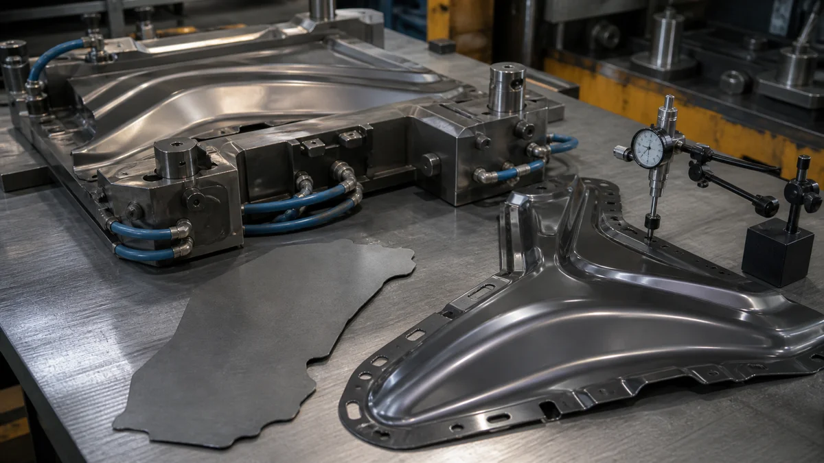
Hot stamping, or press hardening in this context, heats a suitable advanced high-strength steel blank, forms it, and quenches it in a cooled die. Forming at elevated temperature and holding shape during quenching can provide strong shape control, but the route introduces requirements absent from ordinary cold stamping.
| Decision area | Cold stamping | Hot stamping or press hardening |
|---|---|---|
| Blank condition | Formed without a press-hardening heat cycle | Heated before forming |
| Shape-control approach | Overbend, coining, draw control, compensated tooling | Forming combined with controlled in-die quenching |
| Tooling emphasis | Mechanical forming and material flow | Forming, cooling, and thermal process control |
| Development scope | Die tryout and process stabilization | Heating, die cooling, forming, quenching, and validation |
| Selection question | Can cold-process controls hold functional geometry? | Does the AHSS requirement justify the thermal route? |
The material specification is the first filter. Do not propose hot stamping simply because a cold-stamped part exhibits springback. The steel must suit the thermal route, and its delivered material condition must satisfy the engineering requirement. Geometry, critical profiles, surface condition, joining operations, inspection level, quantity, and production intent also affect feasibility.
Compare the complete routes, including tool design, heating strategy, cooled-die development, tryout, sample approval, dimensional inspection, and any required material verification. Press cycle time alone omits the main tooling and validation commitments.
Permit hot stamping as an alternative only when the material and production plan support it. Otherwise, evaluate proportionate cold-forming measures first: stable draw-in, overbending, localized coining, staged forming, and die compensation.
How Should Springback Inspection and RFQ Requirements Be Defined?
Define whether springback-sensitive geometry is accepted free-state, in a specified fixture, or assembled, then connect each critical angle, profile, radius, and flatness control to functional datums and inspection evidence. A complete RFQ must also document material, geometry, volume, tooling intent, revision, and delivery requirements.
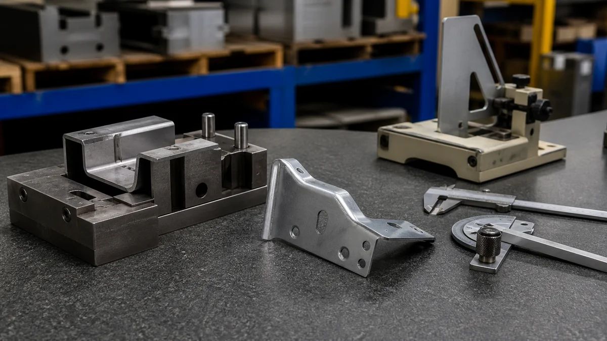
Springback acceptance remains ambiguous until the measurement state is defined. A flexible stamping can meet profile while restrained and move after release. Free-state inspection is often the clearest basis for delivered geometry, but a defined fixture or assembled condition may be appropriate when it represents function. State how the part is located and which result governs.
RFQ and approval checklist
- Current 3D model showing complete formed geometry.
- Controlled 2D drawing with units, part identity, active revision, and governing-document statement.
- Exact material grade, condition or temper, thickness, and grain direction.
- Immediate quantity, prototype, pilot, or production intent, expected repeat demand, and lot assumptions.
- Functional datums and localized controls for critical angles, radii, flange positions, walls, flatness, and profiles.
- Surface finish, cosmetic zones, permitted tool marks, burr direction, and secondary operations.
- Free-state, defined-fixture, or assembled measurement condition, including the locating method.
- First-article requirements, production sampling, final dimensional reporting, and selected full-inspection characteristics.
- Material-lot controls and reapproval triggers, including changes to grade, condition, thickness, source, tooling, or process.
- Tooling ownership and approval expectations, permitted geometry alternatives, and allowed secondary corrections.
- Delivery expectations and sample, pilot, or production-release milestones.
- Confirmation that the intended process is dedicated-die metal stamping rather than CNC turret punching or another sheet metal fabrication route.
Common mistake: A drawing applies one angular tolerance to several bends without defining the datum, inspection state, or sampling frequency. Each supplier may then quote different tooling and verification assumptions. Characteristic-level acceptance8 makes quotations more comparable and gives die tryout a measurable target.
The inspection method should follow the characteristic. An accessible angle may need a different approach from a free-state wall profile or overall formed-part flatness. Define the required result and evidence instead of prescribing one device for every check.
For a springback-control recommendation, sample plan, or quotation, send the 3D model, controlled 2D drawing, material grade and thickness, grain direction, quantity, prototype or production intent, critical tolerances, surface finish, inspection expectations, revision level, tooling status, and delivery requirements.
References
-
Sheet Metal Stamping Dies & Processes - SME - Stamping dies are the tools that shape and cut sheet metal parts. They are commonly developed using computer-aided design (CAD) software and analytical ... ↩
-
Springback - AHSS Guidelines - The magnitude of springback is proportional to the elastic modulus, yield strength and work hardening of the sheet metal, in addition to the part design.E-2 ↩
-
Mastering Springback: A Guide to Sheet Metal Bending ... - Springback is a common challenge in sheet metal bending that can affect accuracy. Learn how to understand, predict, and compensate for springback. Implementing ... ↩
-
Coining in Sheet Metal Bending: Why the Highest ... - Coining eliminates springback by crushing and restructuring the metal at a microscopic level. Coining relies on intense plastic deformation to ... ↩
-
Design of over-crown in sheet metal stamping using finite ... - by H Livatyali · 2006 · Cited by 18 — This compensation method assumes the necessary geometry change due to springback same as the springback and modifies the draw die surface geometry same amount ↩
-
Die design method for sheet springback - by W Gan · 2004 · Cited by 443 — A new method for designing general sheet forming dies to produce a desired final part shape, taking springback into account, has been developed. ↩
-
Deformation Analysis of Side-Wall Curl in the Sheet-Metal ... - The side-wall curl occurring in the sheet-metal forming process of a flanged channel was examined by a proposed theoretical model in the present study. ↩
-
How to Understand GD&T Markings on Stamping Parts Drawings ... - To understand GD&T markings on stamping parts drawings, read each feature control frame left to right: symbol, tolerance value, modifiers, then datums in order ... ↩