
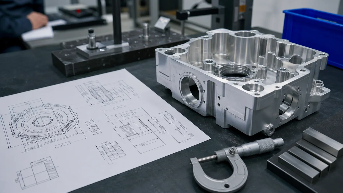
A useful CNC machining quote depends on more than the visible part geometry. The supplier needs to know which dimensions control fit, which surfaces locate the part in assembly, how critical features relate to those surfaces, and what inspection evidence the buyer expects. GD&T communicates that intent well when each control has a clear functional purpose.
Poorly chosen datums, incomplete position callouts, and blanket geometric tolerances create uncertainty. A supplier may have to allow for extra setups, finishing passes, workholding controls, and inspection. Under-specification creates a different risk: a part can satisfy individual size dimensions yet still fail to align, seal, or assemble.
Before requesting prices, separate ordinary dimensions from function-critical features and controlled relationships. Then check whether the datum scheme, part geometry, inspection scope, and RFQ package let the supplier evaluate manufacturing risk without guessing.
When Should You Use GD&T Instead of Plus-or-Minus Tolerances?
Use plus-or-minus tolerances when feature size alone controls acceptance. Use GD&T when function depends on form, orientation, or location relative to other features. The choice should follow assembly behavior, not a general preference for tighter or more sophisticated drawing notation.
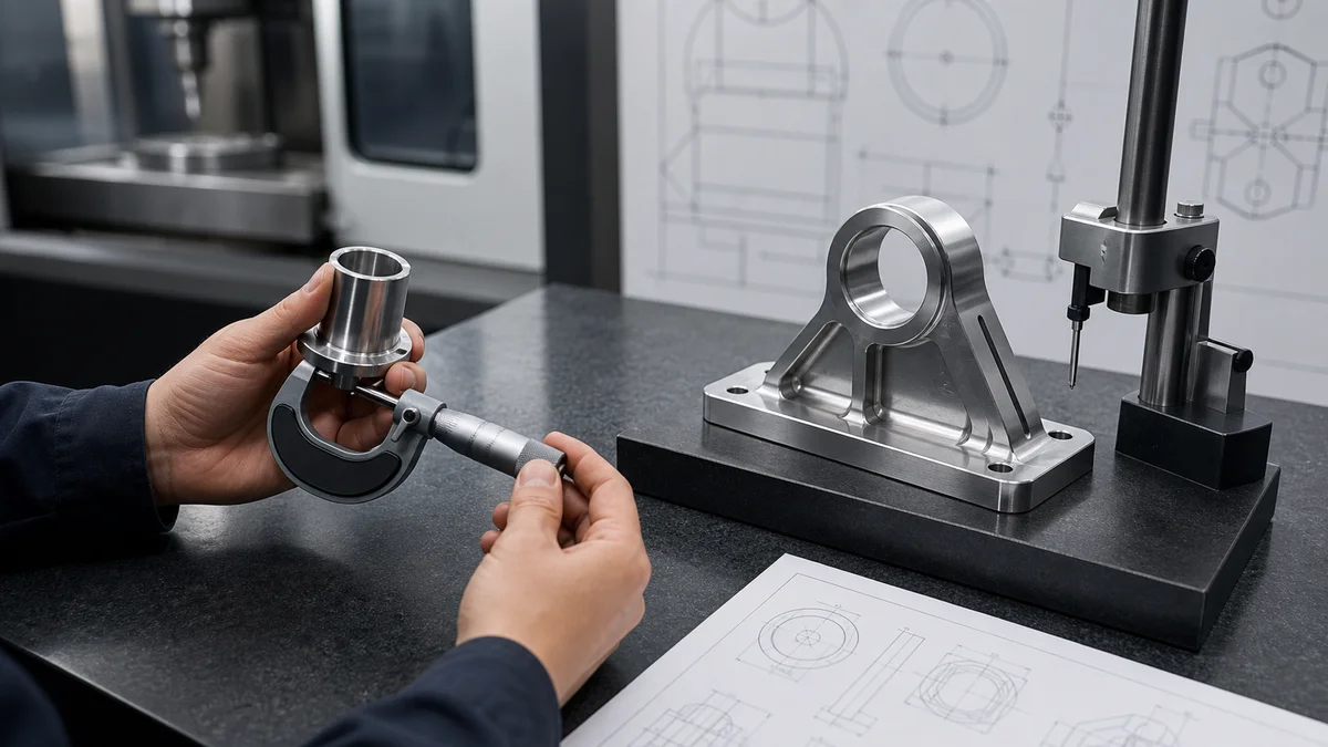
A size tolerance defines how large or small a feature may be. It can be sufficient for a clearance diameter, pocket width, overall length, or another feature whose relationship to surrounding geometry is not critical.
GD&T becomes useful when acceptance depends on a geometric relationship. A sealing face may need flatness. A bore may need perpendicularity to a mounting face. A fastener or dowel pattern may need position relative to assembly datums. Rotating features may require an appropriate runout or axis control.
| Functional requirement | Suitable specification | Practical application |
|---|---|---|
| Control feature size only | Plus-or-minus, limit, or fit tolerance | Clearance width or diameter |
| Control one surface's form | Flatness or profile, as applicable | Sealing or mating face |
| Control orientation to a datum | Perpendicularity or parallelism | Bore relative to a mounting face |
| Control feature location | Position or profile relative to datums | Fastener or dowel-hole pattern |
| Control rotating relationships | Appropriate runout or axis control | Journal or coaxial bore relationship |
The drawing should follow geometric product specification principles1: define the permissible geometry that protects function without adding unrelated restrictions. Applying flatness, profile, position, and parallelism to the same non-critical feature may increase machining and inspection work without improving acceptance.
Coordinate dimensions can also create tolerance stack-up. If a pattern is dimensioned by chaining one hole from the next, variation can accumulate across the pattern. Basic dimensions and position relative to functional datums usually communicate the intended relationship more directly.
Before release, name the failure being prevented: interference, leakage, misalignment, poor motion, or an assembly gap. If size alone prevents it, a size tolerance may be enough. If the failure depends on a relationship, GD&T is the clearer tool.
How Should You Set General Tolerances Before Adding GD&T?
Set a general tolerance in the drawing notes or title block for ordinary dimensions, then apply explicit tolerances and GD&T only to justified exceptions. The baseline must suit the material, part size, feature geometry, finishing sequence, and supplier capability rather than act as a universal machining promise.
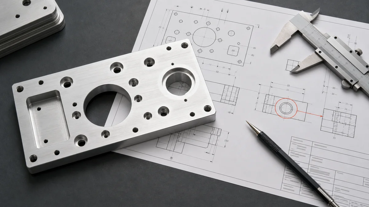
The general tolerance block defines what applies when an individual dimension has no separate tolerance. It keeps ordinary edges, clearance pockets, lightening cuts, and non-contact surfaces from being interpreted as precision features.
For many non-critical aluminum CNC machined features, approximately ±0.10 mm to ±0.13 mm can serve as a practical quoting baseline when closer control is unnecessary. That range is supplier- and geometry-dependent, not a universal capability. An ISO 2768 general tolerance reference2 may be appropriate when its scope and tolerance class fit the drawing.
Before approving the baseline:
- Confirm the drawing units and the dimensional ranges covered.
- Define angular requirements separately where necessary.
- Check the baseline against material grade, part envelope, wall thickness, and feature type.
- Exclude bearing bores, press fits, sealing faces, dowel holes, and alignment features that need explicit control.
- State whether critical dimensions apply before or after anodizing, plating, or another finish.
- Remove decimal places that imply precision without defining a corresponding tolerance.
A nominal dimension written with extra zeros is not a reliable substitute for an allowable variation. State the requirement through the tolerance block, an explicit size tolerance, a fit designation, or an appropriate geometric control.
Common mistake: Repeating a close bilateral tolerance beside almost every dimension defeats the purpose of the general block. It can lead the supplier to plan extra finishing and inspection even though only a few interfaces control fit. A tiered drawing is clearer: ordinary features follow the baseline, while functional exceptions receive specific limits.
How Should You Choose Functional Datums for a Machined Part?
Choose datums from the surfaces, axes, or features that locate the part in its real assembly. The datum sequence should constrain the part logically while remaining stable, accessible, and repeatable enough for machining and inspection without changing the functional meaning.
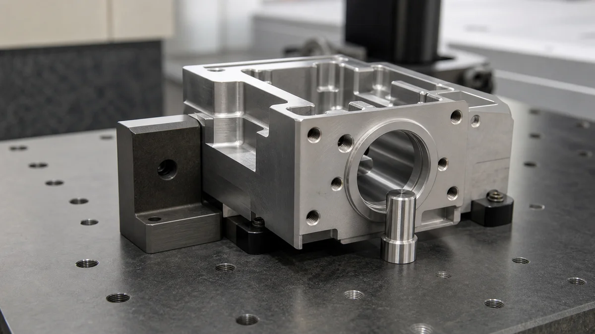
A datum is a theoretically exact reference derived from a selected datum feature. The primary, secondary, and tertiary sequence establishes how the part is oriented and located before controlled features are evaluated.
Start with the feature that provides the most important seating relationship. On a prismatic housing, this may be a broad mounting face. A bore, boss, edge, or hole pattern can then establish direction or lateral location. A third feature removes the remaining degree of freedom. For a turned component, a functional axis and an end face may form a better reference system.
Can the datum be established consistently?
A functionally meaningful feature may still be a poor datum if it is small, interrupted, flexible, inaccessible after finishing, or located on a thin wall. Check whether the supplier can contact or derive it without distorting the part. Burrs, edge breaks, surface texture, and finish buildup can also make datum establishment unstable.
Scenario: A machined housing seats on a broad base and aligns in assembly through one bore and a side face. The base can serve as primary datum A, the bore axis as secondary datum B, and the side face as tertiary datum C. This functional datum selection method3 mirrors the locating sequence. Choosing an unrelated cosmetic top face as datum A may simplify the drawing view but fail to protect assembly alignment.
The datum scheme should also reduce unnecessary tolerance stack-up. Dimensions and feature controls taken from the same functional references are easier to interpret than chains built from incidental edges. The final frame must describe how the component functions and how conformance will be evaluated, not merely how it appears in CAD.
What Must a Complete Hole-Position Callout Define?
A complete hole-position requirement must define hole size separately, identify the positional tolerance zone, reference the required datums in order, and state any justified material condition modifier. It should also make the pattern, basic locations, and inspection expectation unambiguous.
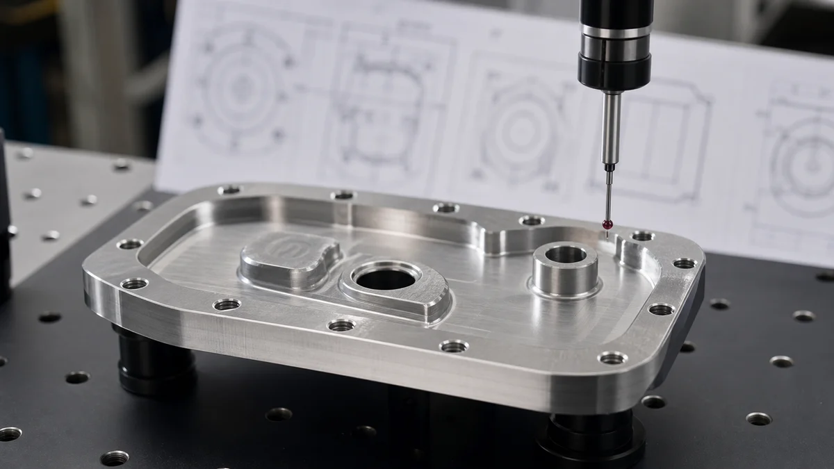
Position controls where a hole axis or pattern may vary relative to the datum reference frame. It does not replace the hole-size requirement. The drawing must communicate both the allowable feature size and the allowable geometric location.
A complete callout should identify:
- The number, diameter, and depth or through condition of the holes.
- The hole-size tolerance or applicable fit.
- Basic dimensions defining the theoretically exact pattern.
- The positional tolerance zone, including a diameter symbol when the zone is cylindrical.
- Primary, secondary, and tertiary datums in their required order.
- Any material condition modifier justified by assembly function.
- Thread, counterbore, countersink, or other feature details.
- The required inspection frequency and reporting scope.
The maximum material condition modifier4 can allow bonus tolerance as a feature departs from its maximum-material boundary. Use it when the functional requirement is based on assembly clearance or another valid boundary condition. Do not add it simply to make the tolerance easier to hold. If location must remain controlled independently of feature size, a different condition may be appropriate.
Example: A cover seats on a mounting face, aligns through two locating features, and contains a fastener pattern that must match a housing. The drawing should establish the mounting and alignment datums, locate the pattern with basic dimensions, define the hole sizes, and apply position to the pattern. A note saying only “true position required” supplies no usable tolerance zone or datum sequence.
Place the callout near the relevant pattern. If two hole groups perform different functions, control them separately rather than forcing both under one frame.
How Do Part Geometry and Setup Changes Affect GD&T Cost?
GD&T generally becomes more demanding when controlled features require different machining orientations, long tool reach, flexible geometry, or repeated reclamping. Mark the cross-setup relationships that truly affect function so suppliers can plan workholding, finishing, and inspection without pricing every feature as equally critical.
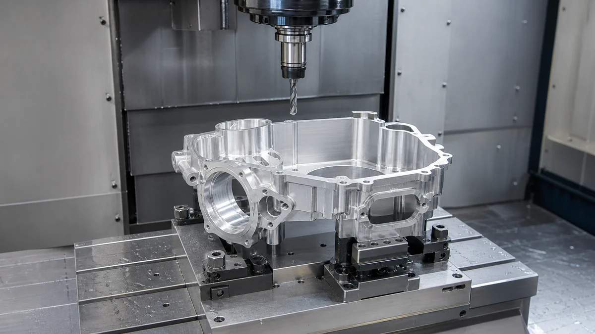
Features produced in one setup can often maintain their relationship through common workholding and a shared coordinate system. When a part must be turned, indexed, or transferred, the supplier must re-establish its references. Tight controls spanning those setups call for more deliberate fixturing and verification.
| Part geometry or control | Machining consequence | Information needed for quoting |
|---|---|---|
| Holes and faces in one orientation | Shared setup reference | Identify the functional relationship |
| Top-to-side or face-to-bore control | Reclamping or indexing | State the controlling datums and tolerance |
| Deep pocket or narrow cavity | Tool reach, deflection, chip evacuation | Show depth, radii, wall thickness, and finish |
| Thin wall or broad plate | Clamp distortion and free-state movement | Define measurement condition |
| Long hole pattern | Positional and thermal sensitivity | Define datums, pattern extent, and inspection scope |
| Finish on a datum or fit feature | Finish buildup may change final size | State pre-finish or post-finish acceptance |
Wall thickness matters because a flexible feature can move under cutting or clamping force. A flatness or profile requirement evaluated after unclamping may be more difficult than the same numerical tolerance on a rigid block. Material grade and condition also affect stability.
Common mistake: Applying close perpendicularity between opposite faces without identifying their function. If one face is cosmetic, the callout may create an unnecessary cross-setup obligation. If both faces locate the assembly, retain the control and ask the supplier to review the multi-setup machining relationship5.
Show critical access directions, deep features, internal radii, and datum relationships. Avoid prescribing a specific machine or fixture unless the process itself is controlled. The supplier needs enough freedom to choose a stable route while still protecting the required geometry.
What Inspection Requirements Should Be Defined Before Quoting?
Define which features require inspection, how often they must be checked, under what condition they are measured, and what evidence must accompany delivery. Inspection method and reporting scope should be agreed with the tolerance because they directly affect quotation effort and acceptance.
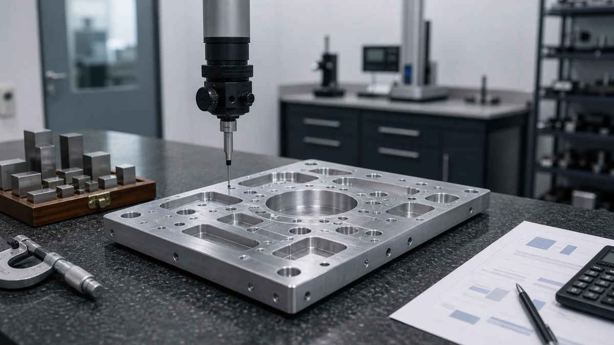
A geometric tolerance is incomplete as a purchasing requirement when the supplier does not know the verification scope. A basic size check differs from evaluating a hole pattern relative to datums or documenting flatness across a broad surface.
Use this dimensional inspection approval checklist6 before sending the RFQ:
- ☐ Identify every critical size and GD&T characteristic requiring documented results.
- ☐ Separate first-article, in-process, final, and recurring-shipment requirements.
- ☐ State which non-critical features may be sampled.
- ☐ Identify any characteristics requiring inspection on every part.
- ☐ Define the expected dimensional or first-article report format.
- ☐ Clarify whether actual values or pass/fail results are required.
- ☐ State whether inspection occurs before or after surface finishing.
- ☐ Define free-state or restrained measurement for flexible and thin-walled parts.
- ☐ Identify any reference-temperature requirement for precision dimensions.
- ☐ Explain how the datum reference frame should be established.
- ☐ List material or other documentation required with delivery.
- ☐ Identify the drawing revision covered by the report.
Do not mandate a particular inspection device merely because a feature uses GD&T. The suitable method depends on tolerance magnitude, feature accessibility, datum establishment, geometry, reporting requirements, and supplier resources. A hand tool may be adequate for some sizes, while flatness, profile, or a positional pattern may need a more structured method.
Example: A broad aluminum plate with a close hole pattern can change dimension with temperature or relax after unclamping. If acceptance depends on a reference temperature or a free-state condition, state that requirement before quotation. Otherwise, the buyer and supplier may use different measurement conditions and reach different conclusions about the same part.
How Can You Avoid Over-Tolerancing the Entire Part?
Classify features by function before assigning tolerances: functional and assembly interfaces may justify close control, while cosmetic and non-contact geometry usually should not inherit the same requirement. Review every demanding tolerance against material, geometry, setup, finish, quantity, and inspection needs.
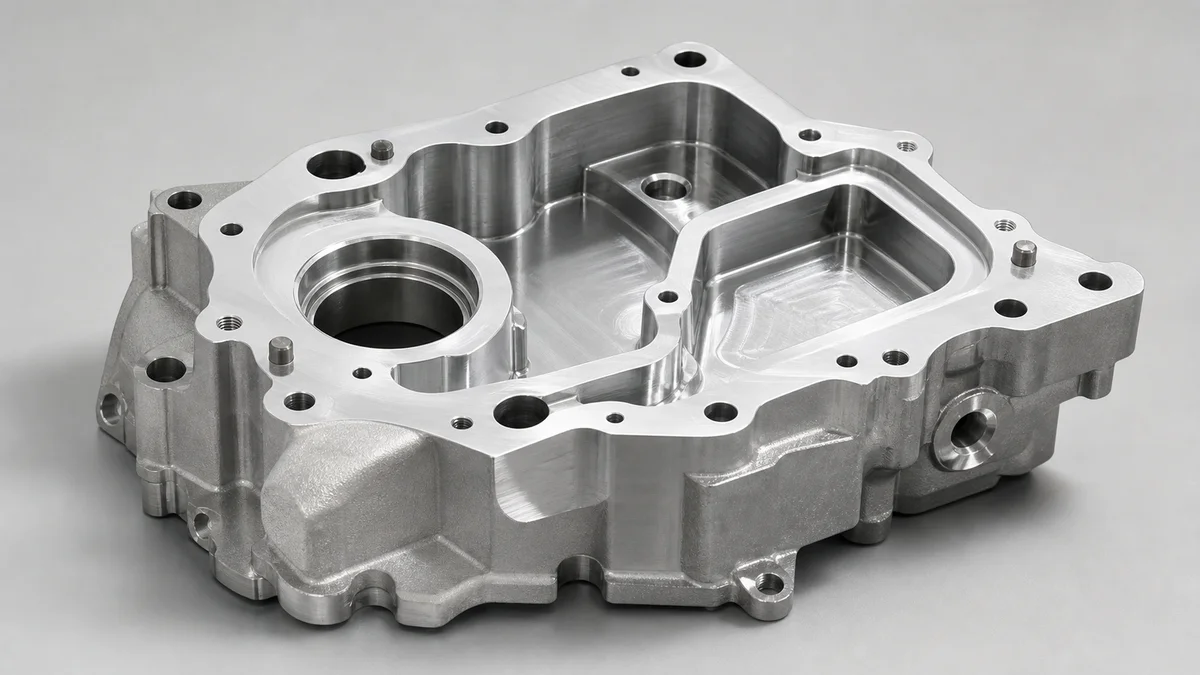
Over-tolerancing often begins when a drawing uses precision as a general signal of quality. A tighter number is not automatically a better specification. It changes the manufacturing and verification obligation even when the feature has no effect on assembly or operation.
Classify the geometry before adding close controls:
- Functional features: sealing faces, bearing seats, sliding surfaces, or other geometry that directly affects operation.
- Assembly features: dowel holes, mating faces, press fits, fastener patterns, and alignment interfaces.
- Cosmetic features: visible surfaces governed mainly by appearance or local surface finish.
- Non-critical features: clearance pockets, lightening cuts, and non-contact edges where normal process variation is acceptable.
Scenario: A rectangular housing has a sealing face, two dowel holes, several clearance holes, a lightening pocket, and a visible top surface. Flatness may be justified on the sealing face, and position may protect the dowel-hole relationship. The clearance holes can have more freedom if assembly allows it. The pocket can remain under the general tolerance, while the top face may need a localized cosmetic finish rather than close geometric control.
Treat aluminum tolerances below approximately ±0.05 mm as a process and inspection decision. Actual difficulty depends on feature size, thin-wall workholding risk7, tool access, temperature, quantity, and whether anodizing or another finish follows machining. This threshold is not a universal capability statement.
Ask what failure each close tolerance prevents. If no clear answer exists, revise the callout or request a supplier review. This diagnostic step is especially important when a tolerance spans multiple setups, applies after finish buildup, or requires documented inspection on every part.
What Should a Complete GD&T RFQ Include?
A complete GD&T RFQ must identify the intended manufacturing process and provide the model, controlled drawing, material, quantity, production intent, critical tolerances, finish, inspection scope, revision, and delivery expectations. Resolve conflicting files and ambiguous process terms before requesting a firm quotation.
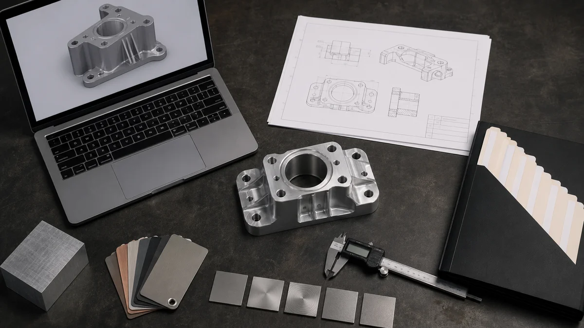
First confirm that CNC machining is the intended process. It removes material from solid stock through milling, turning, drilling, boring, reaming, or related operations. CNC turret punching and CNC punch press work use programmed punch tools on sheet. Metal stamping cuts or forms sheet with dedicated dies. Sheet metal fabrication may combine cutting, punching, bending, welding, and finishing. Plastic injection molding forms polymer in a mold.
“CNC turret punching, CNC punch press, CNC-controlled stamping equipment, or metal stamping depending on the actual process” is not one standard process term. Clarify whether it means CNC turret punching, CNC punch press work, CNC-controlled stamping equipment, or general metal stamping. Burr direction and springback may matter for punched, bent, or stamped sheet, while draft and gate location apply to molded-part and mold design. Those requirements do not belong in a CNC machining specification unless the project includes the relevant secondary or alternative process.
Use this CNC machining RFQ package checklist8:
- ☐ Complete 3D model in a usable native or neutral format.
- ☐ Controlled 2D drawing with units, datums, tolerances, GD&T, and revision.
- ☐ Statement identifying which file governs if the model and drawing conflict.
- ☐ Exact material grade and condition or temper.
- ☐ Immediate quantity and expected annual usage when known.
- ☐ Prototype, validation, pilot, or repeat-production intent.
- ☐ Identification of functional, assembly, cosmetic, and non-critical features.
- ☐ Surface finish, deburring, edge, coating, masking, and secondary operations.
- ☐ Statement defining whether dimensions apply before or after finishing.
- ☐ Inspection frequency, reports, and measurement conditions.
- ☐ Delivery expectations and any partial-shipment requirement.
- ☐ Contact for technical questions and specification clarifications.
This package lets the supplier evaluate material sourcing, tooling, setup count, workholding, machining, finishing, inspection, and schedule as one plan rather than filling gaps with assumptions.
For a manufacturing recommendation or quotation, send the 3D model, controlled 2D drawing, exact material grade, quantity, prototype or production intent, critical tolerances, GD&T callouts, surface finish, inspection expectations, revision level, and delivery requirements. Highlight the features that control fit, sealing, alignment, or motion.
References
-
ISO 1101:2017(en), Geometrical product specifications (GPS) - The orientation plane is only used for this purpose when the toleranced feature is a median feature (centre point, median straight line) and the tolerance zone ... ↩
-
General ISO Geometrical Tolerances Per. ISO 2768 - Engineers Edge - ISO 2768 and derivative geometrical tolerance standards are intendedto simplify drawing specifications for mechanical tolerances. ↩
-
Datum Feature - GD&T Basics - A feature control frame will reference as many datums features as necessary to lock in all the necessary degrees of freedom, this creates what is known as a ... ↩
-
Maximum Material Condition (MMC) - GD&T Basics - The amount of 'bonus' tolerance is equal to the amount of departure from the specified material condition. For example, say you have a through ... ↩
-
CNC Setup: Workholding, Tool Offsets & Accuracy - JLCCNC - Even a correct NC program can fail if offsets, fixturing, or coordinate references are set incorrectly on the machine. ↩
-
Dimensional Metrology Group | NIST - The Dimensional Metrology Group (DMG) provides unique high-accuracy length-based (dimensional) measurement services and leads documentary standards efforts. ↩
-
Thin Wall CNC Machining: Process, Deformation & Cost - JLCCNC - Workholding-Induced Distortion Thin walls are sensitive to clamping because they lack structural stiffness. ↩
-
CNC Machining RFQ Template Guide - uneed - CNC Machining RFQ Template Guide: Get faster quotes! Use our checklist for tolerances, parts, and materials. Simplify your CNC machining quoting process. ↩