

Bend radius and K-factor serve different purposes in a sheet metal specification. Inside bend radius defines physical formed geometry. K-factor helps calculate bend allowance and the developed blank. Confusing them can produce a correct-looking 3D model but a flat pattern that does not form to the required dimensions.
Start with the delivered part: material grade and temper, thickness, bend angles, radii, flange dimensions, nearby features, and functional tolerances. The fabricator can then validate bend deductions or K-factor values against the selected tooling and forming method.
The practical task is to separate controlled product requirements from process-development inputs, then define how the production flat and formed first article will be approved.
What Is the Difference Between Bend Radius and K-Factor?
Inside bend radius is a measurable feature of the formed part, while K-factor is a calculation input locating the neutral axis through the sheet thickness. Specify the required radius on the drawing and use a validated K-factor to calculate bend allowance and the developed blank.

During bending, material on the outside of the bend stretches while material on the inside compresses. Between them is the neutral axis, where length is treated as unchanged. K-factor expresses the neutral axis location relative to sheet thickness1 and supports calculation of the material consumed by the bend.
These terms have distinct specification roles:
| Term | Specification function | Controlled location | Acceptance basis |
|---|---|---|---|
| Inside bend radius | Defines the physical inside curvature | Formed 3D model and controlled drawing | Formed-part verification |
| K-factor | Locates the neutral axis for flat development | CAD settings, calculation record, or supplier bend data | Resulting blank produces the controlled formed geometry |
| Bend allowance | Assigns developed length to the bend region | Flat-pattern calculation | Validated production flat |
| Bend deduction | Adjusts outside formed dimensions to derive blank size | Bend table or fabricator calculation | Required dimensions after forming |
A provisional K-factor can support estimating or early CAD development. It does not replace the inside radius, bend angle, or critical flange dimensions. Conversely, a specified radius cannot fully determine the blank because material condition, actual thickness, tooling, and forming practice still influence elongation.
On the controlled drawing, dimension the inside radius wherever it affects fit, clearance, strength, or appearance. In the flat-pattern notes, state whether the supplied development is controlled, reference-only, or open to fabricator adjustment. That division keeps a calculation assumption from becoming an unintended product acceptance requirement.
Should You Specify a Fixed K-Factor on the Drawing?
Do not treat one K-factor as a universal material constant. A design value may support preliminary flat development, but the production value should normally be confirmed against the specified material, actual thickness, bend geometry, grain direction, forming method, tooling, and fabricator practice.
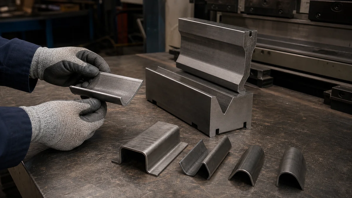
A fixed K-factor can be appropriate when one organization controls the material, tooling, forming method, and validation process. It becomes unreliable when the same number is transferred to another material condition, thickness, press-brake setup, or supplier without confirmation.
Before making K-factor a controlled input, verify that these conditions are stable:
- Exact material grade and temper or condition
- Actual sheet thickness
- Inside bend radius and bend angle
- Bend orientation relative to grain direction
- Air bending, bottoming, or another identified method
- Tooling used to form the bend
- Machine and setup practice
- Evidence from first articles or established bend data2
Scenario: A buyer develops a bracket with a design-stage K-factor and sends the resulting flat to a new fabricator as a fixed requirement. The fabricator uses different tooling and calibrated bend deductions. Cutting the customer flat unchanged could shift the finished flange dimensions even though the formed CAD model looks correct. This is a teaching scenario, not a customer case.
In most supplier-facing drawings, I would control the formed geometry and mark the customer flat as reference-only unless the buyer owns a proven process. If the K-factor must remain fixed for an internal production system, the RFQ should record its associated material, thickness, bend method, tooling assumptions, and approval basis.
Recheck the calculation after a material-source, thickness, tooling, or forming-method change. Preserving the same numerical K-factor matters less than confirming that the revised process still produces the specified formed dimensions.
Should the Drawing Control the Formed Part or the Flat Pattern?
The controlled drawing should normally make the formed part the acceptance basis. Define bend angles, inside radii, critical flange dimensions, and tolerances, then state whether the customer flat pattern is controlled or reference-only and who may adjust it for production tooling.
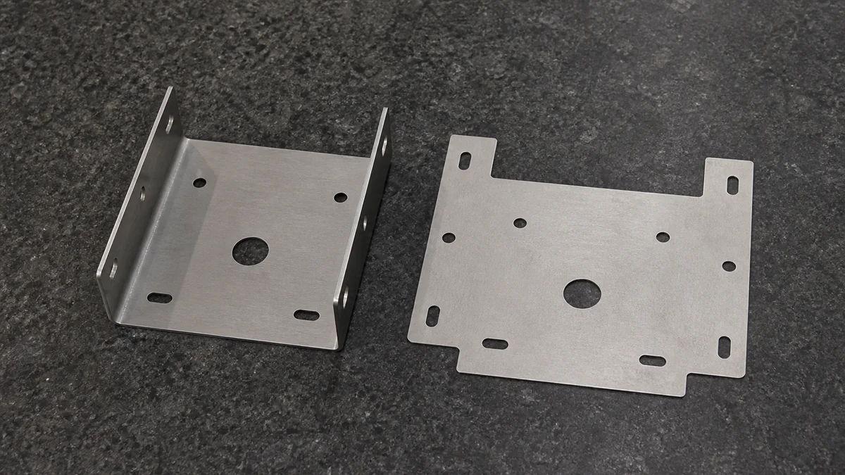
The delivered component must fit its assembly and perform its intended function. The specification should therefore prioritize dimensions measured after forming instead of forcing an unverified intermediate blank to remain unchanged.
Control the features that matter in the finished state: flange lengths, overall envelope, bend angles, inside radii, post-bend hole locations, and functional relationships between formed faces. Mark the cosmetic face and acceptable tooling-mark condition where appearance matters. Ordinary dimensions may remain under a general tolerance, while assembly-critical dimensions should receive explicit limits.
When can the flat pattern be controlled?
A controlled flat may be justified when the buyer owns a validated forming process, supplies pre-cut blanks, or requires one development across an established production route. The package should then identify the governing flat revision, material and thickness assumptions, tooling basis, and change-approval route.
If the flat has not been validated with production tooling, label it as reference geometry. Allow the fabricator to adjust bend allowance or bend deduction while preserving the controlled formed requirements. This avoids a tolerance conflict in which both the flat length and final flange dimension are mandatory but cannot be achieved together under the selected process.
A frequent specification mistake is sending tightly controlled flat and formed dimensions without defining precedence. Resolve that before quotation. Assign production-flat ownership3 to the buyer, fabricator, or a shared approval process. Revision control should connect the approved flat, formed first article, drawing revision, material condition, and any authorized adjustment. The supplier then knows what may change and what must remain fixed.
How Should Material and Forming Method Determine Bend Radius?
Select inside bend radius with the exact material grade, temper, thickness, grain direction, bend angle, and forming method in view. Treat simple thickness-based radius rules as preliminary DFM references, then request supplier review when cracking, springback, clearance, appearance, strength, or tooling limits matter.
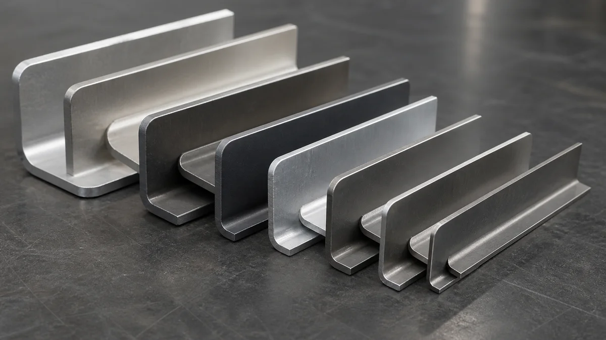
Bend radius is a functional geometry decision, not merely a CAD preference. It affects material flow, outside stretch, springback, flange geometry, and tool selection. Sheets with the same nominal thickness can respond differently when grade, temper, grain orientation4, or forming method changes.
Use the specification inputs below as one coordinated review:
| Input to specify or confirm | Manufacturing consequence | Drawing or RFQ action |
|---|---|---|
| Material grade and temper | Changes ductility and forming response | Name the exact condition |
| Actual thickness or gauge | Affects bend calculation and tool choice | State thickness and its tolerance basis |
| Grain direction | May change cracking risk at a given orientation | Mark it when function requires control |
| Inside radius | Controls clearance, outside stretch, and local geometry | Dimension functional radii explicitly |
| Bend angle | Influences the developed bend region and springback | Define the required formed angle |
| Forming method | Air bending and bottoming use different process assumptions | Let the supplier confirm the viable route |
Harder or less ductile material conditions, including some aluminum tempers, may need a larger radius than a simple one-times-thickness rule suggests. That is a DFM principle, not a universal minimum.
When packaging restricts the bend, show both the preferred radius and the largest acceptable radius or mating envelope. This gives the fabricator room to evaluate tool access without weakening the functional requirement. Also identify whether visible surfaces can accept normal tooling marks. A radius that is geometrically possible may still conflict with the material condition, flange length, cosmetic face, or available forming sequence.
When Should Bend Radii Be Standardized Across a Part?
Standardize bend radii across a part when fit and function permit, because consistent radii can simplify tooling review, setup planning, bend calculations, and inspection. Retain a different radius only when clearance, strength, appearance, or a mating interface provides a documented functional reason.

Arbitrary radius variation forces the fabricator to review more tool combinations, bend deductions, and setup sequences. Even when every bend is feasible, unnecessary differences make quotation, programming, and revision control harder to interpret. A common radius is a sensible default when the bends share material, thickness, and forming conditions.
Before approving a radius exception5, ask what it protects:
- Clearance around a mating component or internal assembly
- A material or strength requirement
- A visible cosmetic transition
- A flange geometry or tool-access constraint
- Compatibility with an existing formed component
- Another documented functional relationship
Standardization is not a blanket note that overrides geometry. Each bend still needs adequate flange length, tool access, relief, and separation from nearby holes or hardware. The aim is to remove variation that has no manufacturing or functional purpose.
Example: A sheet metal cover contains six bends with three modeled radii because reused CAD features carried different defaults. Only one bend wraps around a mating insert and needs a special radius. The drawing can mark that bend as an exception and use a common radius for the other five, subject to supplier DFM confirmation.
A special radius may require a tool change, separate calculation, different setup, or additional inspection. Those effects are supplier- and geometry-dependent, so avoid unsupported cost or schedule claims. Instead, identify the functional exception and allow the supplier to confirm how it affects the production plan. This preserves design intent while avoiding accidental complexity.
How Should Features Near Bend Lines Be Specified?
Specify holes, slots, notches, hardware, edges, and reliefs near bends according to material thickness, inside radius, post-bend location, and the supplier’s forming process. Avoid one universal spacing rule; control functional locations after bending and request DFM review where distortion or interference is possible.
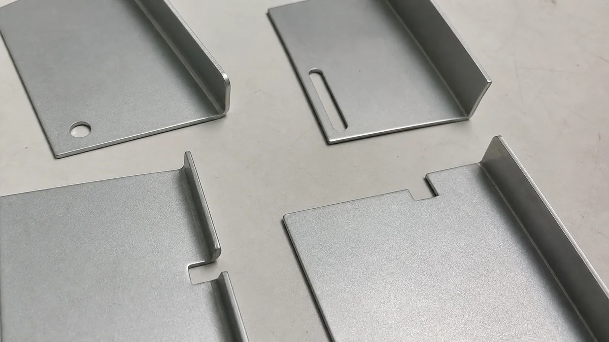
A feature near a bend can enter the deformation zone6, shift as the flange forms, or block the intended tooling. The drawing should show its relationship to the bend and state whether the pre-bend position or final formed position controls acceptance.
Review each feature by function:
- Holes and slots: Control assembly-critical locations after bending. A nearby feature may elongate, move, or lose its intended edge condition.
- Notches and cut edges: Check whether the bend terminates at an unsupported edge or creates a local tearing risk.
- Inserted hardware: State whether installation occurs before or after bending and whether it obstructs forming access.
- Bend reliefs: Define relief geometry where adjoining flanges or cutouts need room to form without overlap or unwanted tearing.
- Cosmetic surfaces: Identify the visible face and permitted tooling-mark condition.
- Burr direction: Control it when the sheared edge affects assembly, handling, finishing, or bend orientation.
Scenario: A mounting slot is dimensioned only in the flat and placed close to a flange. After bending, its functional distance from the formed face depends on the bend result. A stronger specification controls the post-bend relationship and asks the fabricator to review slot position, relief geometry, and forming sequence. This is a teaching scenario.
Do not apply one unsupported minimum spacing to every material and bend. Feasibility depends on thickness, radius, feature shape, grain direction, tooling, and sequence. If the location cannot move, mark it critical and permit review of a revised blank, alternate sequence, or secondary operation after forming.
How Should First Articles and Production Bends Be Inspected?
Inspect the formed characteristics that control assembly, including flange dimensions, bend angles, inside radii, and nearby feature locations. Use a first article to validate springback compensation and the production flat pattern, then define sampling, reporting, and reapproval triggers for repeat production.
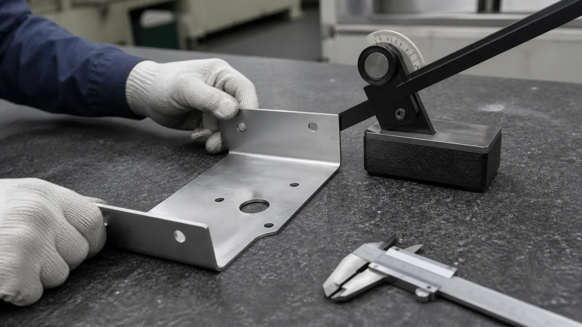
First-article approval7 should connect the controlled drawing, material condition, production flat, forming setup, and measured result. Checking only that the blank matches CAD does not prove that the formed component meets its functional dimensions.
Use a bend approval checklist that covers the full manufacturing state:
- Confirm the part number and active drawing revision.
- Confirm material grade, temper or condition, and thickness basis.
- Record the production flat-pattern revision and owner.
- Verify critical flange and overall formed dimensions.
- Verify controlled bend angles and inside radii.
- Check post-bend holes, slots, notches, and hardware locations that affect assembly.
- Evaluate springback compensation through the achieved geometry.
- Inspect the cosmetic face and allowed tooling marks where specified.
- Record approved flat-pattern adjustments or deviations before batch release.
- Define first-piece checks, batch sampling, final reporting, or other continuing inspection.
The inspection method should fit the characteristic. An accessible flange dimension, an inside radius, a bend angle, and a relationship between formed faces may require different measurement approaches. Specify the evidence needed for acceptance rather than mandating one device for every feature.
Reapproval may be appropriate after a drawing revision, material or thickness change, new material source, tooling change, forming-method change, or production transfer. Such a change does not automatically invalidate the old bend data, but it should prompt confirmation that the established bend allowance or deduction still produces the required part.
Approving a visual sample without its flat revision and actual critical measurements leaves repeat production without a controlled reference.
What Should a Bend-Specific Sheet Metal RFQ Include?
A bend-specific RFQ should define the formed geometry, material condition, thickness, quantity, production intent, tolerances, finish, inspection, revision, and delivery expectations. It should also assign flat-pattern ownership and name the intended manufacturing process clearly enough for the supplier to quote without hidden assumptions.

Send one controlled package so every supplier quotes the same formed requirement. Include:
- Formed 3D CAD model
- Controlled 2D drawing with units and active revision
- Exact material grade and temper or condition
- Actual sheet thickness or gauge requirement
- Immediate quantity and expected repeat demand, when known
- Prototype, validation, pilot, or repeat-production intent
- Inside bend radii and required bend angles
- Critical flange, envelope, and post-bend feature dimensions
- General tolerances and explicitly marked functional tolerances
- Grain-direction requirement, when functionally necessary
- Bend reliefs, notches, holes, slots, and hardware sequence
- Cosmetic face, surface finish, burr direction, and allowed tooling marks
- Inspection characteristics, frequency, and reporting expectations
- Delivery expectations and staged approval requirements
- Flat-pattern status: controlled, reference-only, or fabricator-owned
- Permission for DFM alternatives and the approval route for changes
Name the process accurately. Sheet metal fabrication may include profile cutting, bending, punching, hardware insertion, welding, and finishing. CNC turret punching or CNC punch press work uses programmed tools on sheet and may be one operation within that route. Metal stamping generally uses dedicated dies. CNC-controlled stamping equipment is a broad description and does not identify one specific process.
CNC machining removes material from solid stock; it is not another name for sheet metal bending. Plastic injection molding forms polymer in a mold and has different tooling and geometry assumptions. “CNC turret punching, CNC punch press, CNC-controlled stamping equipment, or metal stamping depending on the actual process” is not a standard process term, so clarify whether the request means CNC turret punching, CNC punch press work, CNC-controlled stamping equipment, or general metal stamping.
Complete process language8 keeps suppliers from quoting different manufacturing routes against the same ambiguous request.
For a manufacturability recommendation or quotation, send the formed 3D model, controlled 2D drawing, material grade and temper, thickness, quantity, prototype or production intent, critical tolerances, surface finish, inspection expectations, revision level, flat-pattern status, and delivery requirements.
References
-
What Are The K Factor, Bend Allowance, And Bend Deduction? - The value of K factors will always be between 0 and 1. If a k factor is 0.25, it means that the neutral axis is located at 25% of the thickness of the sheet ... ↩
-
Sheet Metal Bend Radius Guidelines - Use your CAD's default K-factor if needed—Protolabs has calibrated values for our tooling and will handle bend allowance/deduction and flattening. ↩
-
Sheet Metal Design for Manufacturing: Tolerances, Bend ... - Bend deduction is the amount subtracted from the total outside dimension of a part to get the flat pattern length. Bend deduction is faster for ... ↩
-
Grain direction's effect on sheet metal bending - The smaller the inside radius is when bending parallel to the grain direction, the greater the chances that cracking will occur, and the more ... ↩
-
Sheet Metal Bending Design Guide: DFM Rules, ... - Standardize Bend Radius Values. Using a consistent bend radius throughout a design reduces tooling changes and improves production efficiency. ↩
-
Design Guidelines for Sheet Metal Fabrication - For hardware holes close to bends, adding cutouts around the hardware hole provides the necessary material relief during bending and leaves the hole undistorted ... ↩
-
First Article Inspection in Sheet Metal Manufacturing - Bend and Form Checks: Verifying bend angles, radii, and overall flat pattern accuracy. Feature Inspection: Checking hole sizes, locations ... ↩
-
CNC Machining vs Stamping: Which Is Best for Your Project? - CNC machining handles thicker and harder materials, while stamping is ideal for thin sheet metal. Is CNC machining more precise than metal stamping? ↩