

Surface roughness affects how a CNC machined surface seals, slides, supports a bearing, mates with another component, accepts a coating, or appears after production. Specifying the lowest possible Ra value is not automatically safer. It can require different tooling, extra finishing passes, broader inspection, or secondary processing without improving function.
A sound specification starts by classifying surfaces. Ordinary faces can often retain a standard machined finish, while sealing lands, bearing journals, sliding areas, and controlled cosmetic faces may need individual callouts. Material grade, geometry, tool access, dimensional tolerance, and the final finishing condition all influence what is practical.
The decisions below explain how to select, locate, communicate, and verify Ra requirements so suppliers can quote the intended machining and inspection scope without relying on hidden assumptions.
What Does an Ra Specification Actually Control?
Ra controls the arithmetic average of absolute surface-profile deviations from a mean line over an evaluation length. It is useful for specifying general roughness, but it does not independently control isolated scratches, high peaks, machining-mark direction, waviness, or the complete visual appearance of a surface.
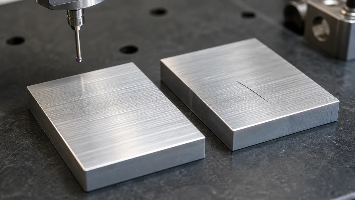
Ra reduces a measured profile to one average value. That makes it useful for comparing surfaces and establishing a measurable texture requirement. It does not reveal how individual peaks and valleys are distributed, however, so two visibly or functionally different surfaces can produce the same Ra result.
That distinction matters on interfaces where the profile shape or direction affects performance. A sealing face may be sensitive to an isolated peak or to tool marks crossing the contact path. A sliding surface may need a defined lay, meaning the predominant direction of its surface pattern. A cosmetic face can satisfy Ra while still showing scratches, dents, chatter, or an inconsistent cutter path.
When is Ra alone insufficient?
Supplement Ra only when another characteristic matters:
- Add Rz when the relevant specification needs peak-to-valley information.
- Define lay direction when texture orientation could affect sealing, sliding, leakage, or wear.
- Add separate visual criteria for scratches, dents, chatter, clamp marks, or texture consistency.
- Bound the measurement area when only part of a face performs the critical function.
Example: A circular sealing land may meet its Ra limit while retaining a directional tool path across the seal. If that direction matters, identify the controlled land and specify the additional texture condition rather than relying on average roughness alone.
Terms such as “smooth,” “mirror finish,” and “no tool marks” are not substitutes for a defined parameter. The arithmetic average roughness definition1 explains what Ra measures, while visual or functional acceptance criteria must address what Ra leaves uncontrolled.
When Should You Use Ra 3.2 µm as the Machined-Finish Baseline?
Use Ra 3.2 µm as a common economical reference for ordinary CNC machined surfaces when no finer condition is functionally necessary. Treat it as a conditional drawing and quoting baseline, not a universal capability guarantee across every material, operation, geometry, setup, or supplier.

A general Ra baseline keeps the drawing readable and gives the supplier a defined condition for surfaces without local callouts. The approved research identifies Ra 3.2 µm as a common reference for standard machined surfaces and Ra 1.6–3.2 µm as a practical range for many commercial CNC parts.
The correct value still depends on the actual component. Material grade and condition affect cutting behavior. Milling, turning, drilling, boring, and reaming generate different textures. Tool access, interrupted cuts, wall stiffness, setup count, and tool condition also influence whether a requirement is straightforward or needs additional process control.
| Surface function | Suggested drawing treatment | Manufacturing consequence |
|---|---|---|
| Ordinary non-contact face | General Ra 3.2 µm note where suitable | Avoids unnecessary fine passes |
| General commercial machined face | Review within Ra 1.6–3.2 µm | Keeps selection tied to material and process |
| Sealing, bearing, or sliding face | Local surface-specific callout | Concentrates machining and inspection on the working area |
| Controlled cosmetic face | Ra plus separate visual criteria if needed | Prevents Ra from being mistaken for appearance control |
| Post-processed surface | State the acceptance stage | Aligns machining, finishing, and final inspection |
Example: A housing may contain clearance pockets, a visible exterior face, and a sealing land. The pockets can remain under the general note, while the exterior face receives cosmetic criteria and the sealing land receives a function-based local callout.
A general machined finish note2 with explicit exceptions is usually clearer than repeating Ra 3.2 µm beside every face. It reduces drawing clutter and makes the surfaces requiring special control immediately visible.
Which Surfaces Should Receive Separate Fine-Ra Callouts?
Apply separate fine-Ra callouts only where texture affects sealing, bearing, sliding, mating, coating preparation, or controlled appearance. Point each requirement to the affected face or a bounded detail view, while leaving non-critical geometry under the drawing’s general machined-finish note.
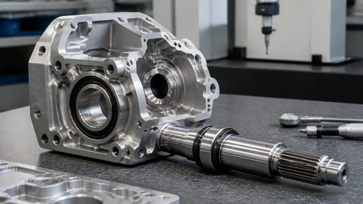
Classify each surface before selecting its roughness value. A clearance pocket does not need the same treatment as a bearing journal or sealing land. Local callouts focus toolpath control, finishing passes, secondary operations, and inspection on surfaces that influence acceptance.
Use a functional surface classification during drawing review:
- Sealing lands: Mark the exact contact area and decide whether Ra, Rz, and lay direction are needed.
- Bearing journals and sliding zones: Define the working length rather than controlling the complete shaft or adjacent shoulders.
- Mating faces: Specify texture where it affects contact or assembly, while keeping size, flatness, and other geometric controls separate.
- Coating-preparation areas: State the required condition and whether acceptance occurs before or after anodizing, plating, or another treatment.
- Controlled cosmetic faces: Combine measurable roughness with visual limits when scratches, chatter, dents, or pattern consistency matter.
- Ordinary or hidden faces: Leave these under the general note unless another function justifies closer control.
A surface texture symbol should point unambiguously to the relevant area. When only a ring, strip, pocket floor, or contact band is controlled, show its boundary in a detail view. Do not make the supplier infer whether the callout covers one face or the entire part.
Common mistake: A blanket note such as “Ra 0.8 µm all over” can extend fine machining and inspection to pockets, clearance faces, clamped regions, and non-contact edges. A surface finish symbol applied locally3 makes the manufacturing scope clearer and reduces acceptance disputes without weakening the functional requirement.
How Should Material and Machining Process Affect the Ra Requirement?
Select Ra with the exact material grade, condition, machining operation, and finishing route in view. Milling, turning, and grinding generate surfaces differently, so published roughness ranges should support supplier review rather than serve as guaranteed limits for every part geometry or production setup.
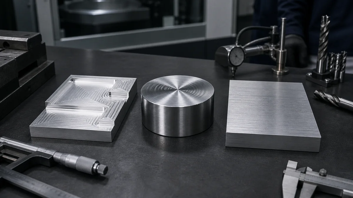
A drawing defines the required result, but the process creates the surface. Milling uses a rotating multi-point cutter, leaving paths influenced by feed, step-over, cutter geometry, and engagement. Turning forms the surface as the workpiece rotates against a cutting tool. Grinding removes material abrasively and may be considered when ordinary cutting does not suit the required finish or dimensional condition.
| Process | Supported Ra reference range | Typical specification consequence |
|---|---|---|
| Milling | 0.8–6.3 µm | Fine values may need smaller step-over, revised toolpaths, or added passes |
| Turning | 0.8–3.2 µm | Finish depends on rigidity, tool condition, engagement, and cylindrical geometry |
| Grinding | 0.2–1.6 µm | Adds a separate operation, handling stage, and verification requirement |
These are process reference ranges4, not promises of capability. A value inside a published band can remain difficult on a deep pocket, thin wall, interrupted diameter, curved face, or surface reached after reclamping. An open, rigid feature may be less demanding under the same nominal requirement.
Specify material by grade and condition rather than using “aluminum,” “steel,” or “plastic” alone. Chip formation, built-up edge, work hardening, heat response, and finishing compatibility can affect surface consistency. They may also change whether the supplier recommends a revised cutting route or secondary finishing.
Scenario: The same fine Ra is requested on a broad milled face and a cylindrical journal. Because the surfaces are generated differently, the supplier may recommend separate finishing strategies. Control the required results, but leave process selection open unless a particular route is functionally necessary.
How Does Part Geometry Change Surface-Finish Difficulty?
Part geometry changes Ra difficulty by controlling cutter access, tool rigidity, workholding, engagement, and setup count. Open rigid faces are generally less risky than deep pockets, narrow cavities, curved surfaces, thin walls, interrupted cuts, or finish-critical areas requiring reclamping or extended tool reach.
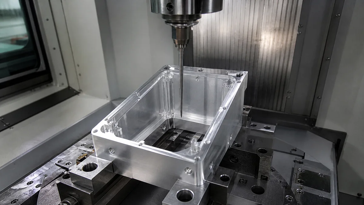
A roughness value cannot be judged independently of its location. The cutter and holder need a clear approach, the workpiece needs stable support, and the finishing pass must avoid excessive deflection or vibration. Restricted access may require a smaller or longer tool, another orientation, lighter cuts, or secondary finishing.
Use geometry as a diagnostic checklist before tightening Ra:
- Deep pockets and narrow cavities: Extended tool reach reduces rigidity and can increase chatter or texture variation.
- Thin walls and flexible sections: Cutting and clamping forces can move the surface during machining or after release.
- Large finish-critical faces: Fine Ra over a broad area expands finishing time and measurement coverage.
- Curved or free-form surfaces: Changing tool contact and orientation can make texture less uniform.
- Interrupted surfaces: Holes, slots, ribs, and gaps repeatedly change cutter engagement.
- Multiple setups: Reclamping can introduce visible transitions and complicate relationships between finish-critical faces.
- No-clamp zones: Cosmetic or functional restrictions can remove convenient workholding locations.
Scenario: Consider a thin-walled housing with a fine-Ra requirement on the floor of a deep internal pocket. The cutter requires extended reach, surrounding walls restrict access, and the floor can deflect under cutting pressure. This teaching scenario does not represent a customer case. Possible reviews include widening the opening, adding support, reducing the controlled area, changing the setup, or allowing a separate finishing route.
The model and drawing should expose the complete geometry, wall thickness, protected edges, and finish zones. A tool access review5 then gives the supplier enough information to judge whether the face can remain conventionally machined or needs a different strategy.
How Should Ra, Dimensional Tolerance, and Inspection Be Coordinated?
Coordinate Ra with dimensional tolerance by defining the parameter, value, unit, exact surface, manufacturing stage, measurement condition, inspection frequency, and required evidence. State whether acceptance applies before or after secondary finishing so roughness verification and dimensional inspection evaluate the same delivered condition.

Roughness, feature size, and geometric tolerance control different characteristics, yet the operation used to achieve one can affect the others. Grinding, lapping, polishing, anodizing, plating, or electropolishing can alter surface condition or final size. The drawing must identify the stage at which each requirement applies.
Use this roughness approval checklist:
- ☐ Identify the parameter as Ra, Rz, or another explicitly required measure.
- ☐ State the value and unit, distinguishing micrometers from microinches.
- ☐ Point to the exact surface or bounded measurement zone.
- ☐ Define lay direction where texture orientation affects function.
- ☐ State any required non-standard sampling or evaluation condition.
- ☐ Identify whether acceptance applies as machined or after secondary finishing.
- ☐ State whether critical dimensions apply before or after that operation.
- ☐ Mark surfaces requiring documented roughness readings.
- ☐ Define first-article, batch-sampling, final-report, or selected full-inspection scope.
- ☐ State the expected report content and controlled drawing revision.
Does every callout need a recorded result?
Not necessarily. Inspection frequency should follow functional risk and production intent. A general machined finish may be handled differently from a sealing land whose measured value is part of delivery acceptance. Make that distinction before quotation so metrology and reporting are not left as assumptions.
Example: A fitted diameter will be polished after turning. State whether both its dimensional tolerance and Ra apply after polishing. Otherwise, the diameter may be checked before material removal while the buyer expects acceptance in the final condition. A defined roughness measurement condition6 keeps machining, finishing, and inspection aligned.
When Does a Fine Ra Requirement Need Secondary Finishing?
A fine Ra requirement needs secondary-finishing review when ordinary milling or turning cannot reasonably produce the required condition on the specified material and geometry. Requirements below Ra 0.8 µm need clear functional justification, while mirror-like conditions may require polishing, lapping, electropolishing, or another separate operation.

Lowering Ra changes the manufacturing plan, not merely the acceptance number. The supplier may need slower feeds, smaller step-over, sharper tool control, extra finishing passes, closer tool monitoring, or broader inspection. The effect grows when fine finish covers a large face, deep pocket, complex contour, multiple orientations, or a repeat-production quantity.
Requirements below Ra 0.8 µm should be tied to a defined need such as sealing, sliding, friction, wear, cleanability, or controlled appearance. The approved research associates mirror-like conditions around Ra 0.05 µm with polishing, lapping, or electropolishing rather than ordinary CNC cutting. Treat that value as a process-planning signal, not a universal supplier boundary.
Secondary operations should be named or explicitly permitted in the RFQ. They may add handling, masking, cleaning, dimensional allowance, queue time, and another inspection stage. Material removal or finish buildup can affect fitted diameters, threads, thin sections, sharp functional edges, and surfaces that must remain untreated.
Common mistake: “Mirror finish” is specified without a measurable value, exact location, visual acceptance rule, or permitted method. Quotations then reflect different assumptions, and final inspection lacks a shared acceptance basis.
Before releasing the drawing, answer four questions:
- What function requires the lower Ra?
- Which exact contact zone needs it?
- Which secondary processes are allowed?
- Do the dimensions and roughness apply before or after that process?
If appearance drives the requirement, keep cosmetic acceptance separate from Ra. A visually uniform surface and a low average roughness can overlap, but they do not describe the same condition. A secondary finishing process7 should therefore be specified with both functional and dimensional consequences in view.
What Should a Surface-Roughness RFQ Include?
A surface-roughness RFQ should identify the correct manufacturing process and provide controlled geometry, material, quantity, production intent, tolerances, Ra values and locations, secondary finishes, inspection scope, revision level, and delivery expectations. Complete inputs let suppliers quote machining, finishing, verification, cost, and schedule consistently.

First confirm that the request concerns CNC machining, which removes material from solid stock through milling, turning, drilling, boring, reaming, or related operations. Do not use unrelated process names interchangeably.
CNC turret punching uses programmed punch tools on sheet metal. A CNC punch press performs that sheet operation. Metal stamping cuts or forms sheet with dedicated dies, while sheet metal fabrication may combine cutting, punching, bending, welding, and finishing. Plastic injection molding forms polymers in a mold. “CNC turret punching, CNC punch press, CNC-controlled stamping equipment, or metal stamping depending on the actual process” is not one standard process term; clarify whether it means CNC turret punching, a CNC punch press, CNC-controlled stamping equipment, or general metal stamping.
Use this RFQ checklist for a CNC machined part:
- ☐ Current 3D model showing complete geometry and finish-critical areas
- ☐ Controlled 2D drawing with units, part identity, and active revision
- ☐ Governing-document statement if the model and drawing conflict
- ☐ Exact material grade and condition
- ☐ Immediate quantity and expected repeat demand when known
- ☐ Prototype, validation, pilot, or repeat-production intent
- ☐ Critical tolerances and relevant datum relationships
- ☐ General machined-finish note
- ☐ Local Ra values, units, symbols, and finish zones
- ☐ Rz, lay direction, or cosmetic criteria where required
- ☐ Polishing, grinding, lapping, coating, or other secondary operations
- ☐ Masking and protected-surface requirements
- ☐ Pre- or post-finish dimensional and roughness acceptance stage
- ☐ Measurement locations, sampling frequency, and report expectations
- ☐ Delivery expectations and approval sequence
The CNC machining RFQ package8 should also identify acceptable alternatives. If suppliers may revise a toolpath, recommend secondary finishing, or propose a rougher value that still protects function, state that flexibility clearly without weakening controlled acceptance requirements.
For a finish recommendation, sample, or quotation, send the 3D model, controlled 2D drawing, exact material grade and condition, quantity, prototype or production intent, critical tolerances, Ra values and locations, permitted secondary finishes, inspection expectations, active revision, and delivery requirements.
References
-
Surface Roughness Parameters | Introduction To Roughness - Arithmetical mean height indicates the average of the absolute value along the sampling length. When dealing with the roughness profile, Ra is referred to as ... ↩
-
Surface Roughness Symbols: Drawing Examples & ISO ... - Many engineering drawings use a general surface finish note that applies to all machined surfaces. Individual surface roughness symbols are ... ↩
-
ISO 1302:2002 - Geometrical Product Specifications (GPS) - This International Standard specifies the rules for the indication of surface texture in technical product documentation (e.g. drawings, specifications, ... ↩
-
CNC Machining Surface Roughness: A Practical Guide - Machining Process, Typical Ra Range (µm), Typical Rz Range (µm) ; Turning, 1.6 – 6.3, 6 – 32 ; Milling, 0.8 – 6.3, 4 – 25 ; Grinding, 0.1 – 0.8, 1 ... ↩
-
CNC Machining Tool Chatter Troubleshooting: Rigidity ... - Machine rigidity issues that cause chatter include compliance in the spindle, axes, slideways, turret, or general machine structure. spindle speed and feed ... ↩
-
Evaluation Length | Surface Roughness Terminology - Evaluation length refers to the part of a given length extracted from the profile in order to determine the arithmetic mean deviation and other roughness ... ↩
-
What is Electropolishing? How Does Electropolishing Work? - Electropolishing improves surface finish by reducing surface roughness by up to 50%. The maximum improvement in surface roughness (Ra, or roughness average) is ... ↩
-
CNC Machining RFQ Template Guide - uneed - Required files and data: CAD, PDF drawings, material, quantities, finishing, timelines. The minimum package for most custom CNC quoting includes the CAD model, ... ↩