
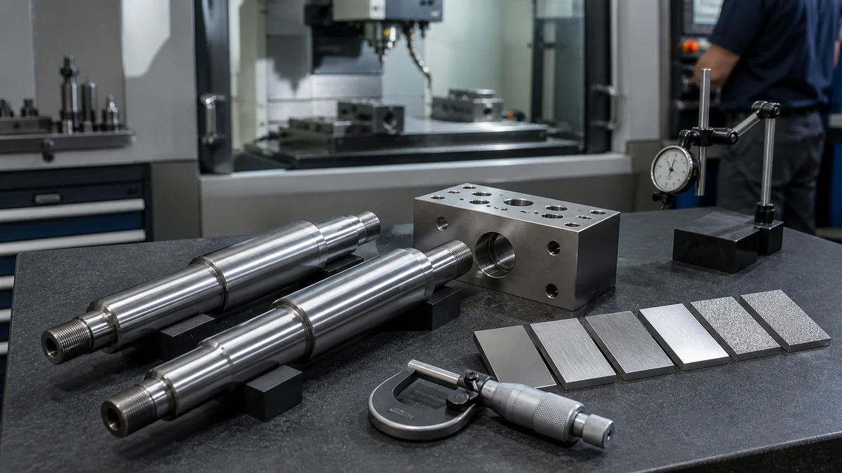
Precision grinding should not be added to every CNC-machined part. Milling and turning can often deliver the required dimensions and surface condition directly. Grinding becomes useful when selected features need tighter final sizing, better geometric form, a finer functional surface, or dimensional correction after heat treatment.
Make the decision feature by feature. A bearing seat may need grinding while nearby clearance diameters remain turned. A sealing face may be surface ground while the rest of its housing remains milled. Material condition, geometry, tolerance, roughness, production quantity, datum strategy, and inspection method all affect whether the extra operation is justified.
The following decisions show where grinding belongs in the manufacturing route and what a supplier needs to recommend and quote an appropriate finishing process.
When Should Grinding Become the Final Sizing Process?
Add precision grinding as the final sizing process when a functional feature approaches the repeatable limits of the proposed milling or turning route. Tolerances around or tighter than ±0.01 mm are useful review signals, but geometry, material, workholding, quantity, and inspection still govern the decision.
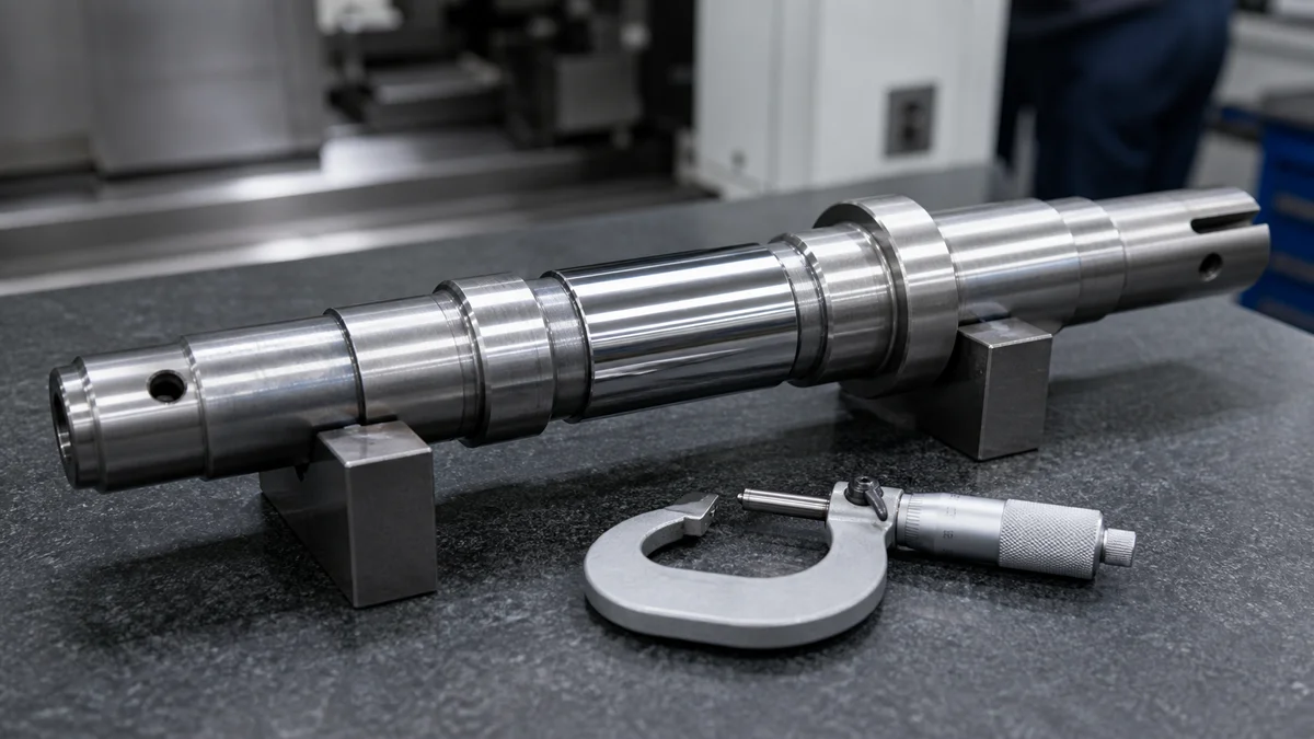
Grinding removes a small, controlled amount of material after the main CNC operations. Milling or turning establishes the general geometry; grinding brings selected faces or diameters to their final size, form, or surface condition.
A tolerance near ±0.01 mm should trigger a process review, not an automatic grinding note. The supplier must consider whether the feature is a short, rigid diameter; a long shaft; a broad plate; a thin wall; or a surface interrupted by holes and slots. Workholding, thermal movement, tool access, batch quantity, and relationships to other features can make the same numerical tolerance manageable on one part and difficult on another.
| Feature | Specification to review | Reason grinding may be needed |
|---|---|---|
| Clearance diameter | Size tolerance and assembly clearance | Usually little benefit if turning meets function |
| Bearing or press-fit seat | Diameter, roundness, fit, and finish | Several acceptance characteristics may coincide |
| Sealing interface | Size, form, roughness, and lay | Correct size alone may not protect sealing |
| Precision shaft | Diameter, taper, datum axis, and stiffness | Deflection or taper may remain after turning |
Example: A shaft has four turned diameters, but only one bearing journal controls fit and rotation. Mark that journal with its final size, form, and finish instead of applying one tight tolerance to the entire shaft.
Ask the supplier to evaluate repeatable CNC machining tolerance1 on the actual material, geometry, quantity, and inspection plan. One conforming sample does not prove that the route is stable for repeat production.
Should Grinding Be Scheduled After Heat Treatment?
Schedule grinding after heat treatment when hardening may move critical dimensions or leave the material difficult to finish by conventional cutting. The usual sequence is rough machining, thermal processing, and final grinding, with intentional stock retained on every surface that may need correction.
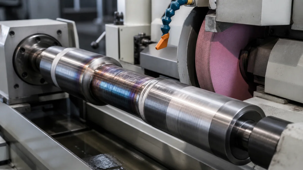
Heat treatment can change size, straightness, flatness, roundness, or relationships between features. The supplied research reports possible movement around 0.02–0.05 mm, but this is not a guaranteed range. Material grade, section thickness, symmetry, treated zone, thermal route, and the pattern of prior material removal all influence the result.
Machining a critical surface to final size before hardening removes its recovery margin. If the part moves during thermal processing, the supplier may have no stock left for correction. A more robust grinding after heat treatment sequence2 establishes the rough geometry, retains a deliberate allowance, completes the specified thermal cycle, and then finishes only the features requiring final control.
Which dimensions apply after heat treatment?
The controlled drawing should identify the final material condition and state which size tolerances, datum relationships, flatness controls, runout requirements, and roughness values apply after treatment. It should also distinguish ground surfaces from those accepted as treated.
Scenario: A hardened steel shaft has a bearing journal beside an axial locating shoulder. The journal needs its final diameter, roundness, and finish after hardening; the shoulder controls assembly location. The route must retain stock on the journal while preserving its relationship to the shoulder. A note saying only “grind after heat treat” leaves the datum and acceptance condition unresolved.
Inspect heat-sensitive characteristics after the last grinding operation. Put any first-article report, sampling plan, hardness evidence, or final dimensional report in the RFQ so the supplier can include the correct verification stage.
When Does Material Hardness Make Grinding the Better Finish?
Grinding may be the better finishing route when hardened metal reaches roughly HRC 45–50 or higher and conventional cutting creates excessive tool wear, heat, surface damage, or dimensional drift. Hardness is only one input; tolerance, geometry, finish, material condition, and tooling access must also support the choice.
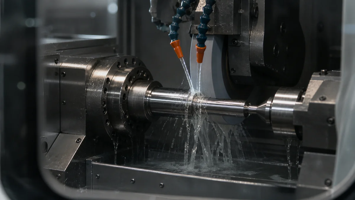
The HRC 45–50 range is a practical review point from the supplied research, not a universal boundary between cutting and grinding. Some hardened features can still be finish-cut. Others may need grinding outside that range because their geometry, surface requirement, or dimensional relationships create different risks.
Review hardened-state finishing when several of these conditions occur together:
- The steel is hardened before critical dimensions are completed.
- Conventional cutting requires long engagement or repeated interrupted cuts.
- Thermal processing may shift a closely controlled feature.
- Surface integrity matters on a bearing, sealing, sliding, or wear interface.
- Tool wear could change size or finish during a repeat batch.
- Only selected hardened surfaces need final material removal.
The RFQ should name the exact grade and incoming condition rather than saying only “hardened steel.” State the final condition or target hardness where applicable, the heat-treatment sequence, and the features finished afterward. These inputs let the supplier compare precision grinding3 with an available hardened-state cutting route.
A common specification mistake is requiring grinding solely because the material is hard. An open, rigid feature with moderate tolerance and finish may remain practical to cut. The opposite mistake is leaving the finishing route unresolved when a hard, slender, or interrupted feature also carries close size, form, and finish requirements. Judge the combined requirement—and the proposed inspection method—not hardness in isolation.
Which Surface Finish Requirements Justify Grinding?
Consider grinding when a functional surface requires approximately Ra 0.8 µm or finer and milling or turning may not produce that condition reliably on the actual geometry. Apply the requirement locally and specify the parameter, value, units, measurement location, inspection frequency, and final manufacturing condition.
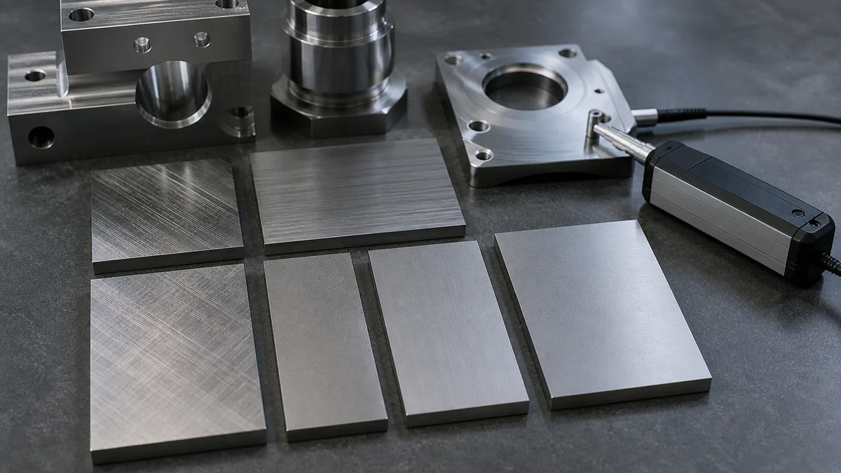
Ra describes the arithmetic average of surface-profile deviations, but it does not fully define scratches, isolated peaks, chatter, or texture direction. A sealing or sliding interface may therefore need a numerical roughness requirement plus a separate control for lay or visible defects. Do not use Ra as a vague synonym for polished appearance.
The following figures are planning references, not guaranteed capabilities for every supplier or geometry.
| Surface condition | Reference range | Drawing and RFQ implication |
|---|---|---|
| Ordinary machined surface | Ra 1.6–3.2 µm | Milling or turning may be sufficient |
| Grinding review point | About Ra 0.8 µm or finer | Evaluate a dedicated finishing operation |
| Referenced ground surface | About Ra 0.2–0.8 µm | Confirm geometry, material, process, and measurement plan |
Localize surface roughness requirements4 to sealing, bearing-contact, sliding, or wear zones. Clearance pockets, hidden faces, cosmetic edges, and non-contact areas should not inherit a fine Ra value unless another function requires it.
Example: A machined block has one sliding guide face and five ordinary exterior faces. Applying Ra 0.8 µm everywhere expands finishing and inspection without protecting another function. Marking only the guide face lets the supplier plan the operation, protect its edges, and take readings at an agreed location.
State whether acceptance applies after heat treatment, grinding, coating removal, or another secondary step. Also define whether roughness readings are required for a first article, a batch sample, or every designated surface.
When Should a Flat Face Be Surface Ground After Milling?
Surface-grind a milled face when its functional flatness, parallelism, or mating contact cannot be achieved reliably through milling alone. Suitable candidates include sealing faces, locating planes, plates, and heat-treated blocks, provided the drawing defines the datum, controlled surface, final condition, and inspection method.
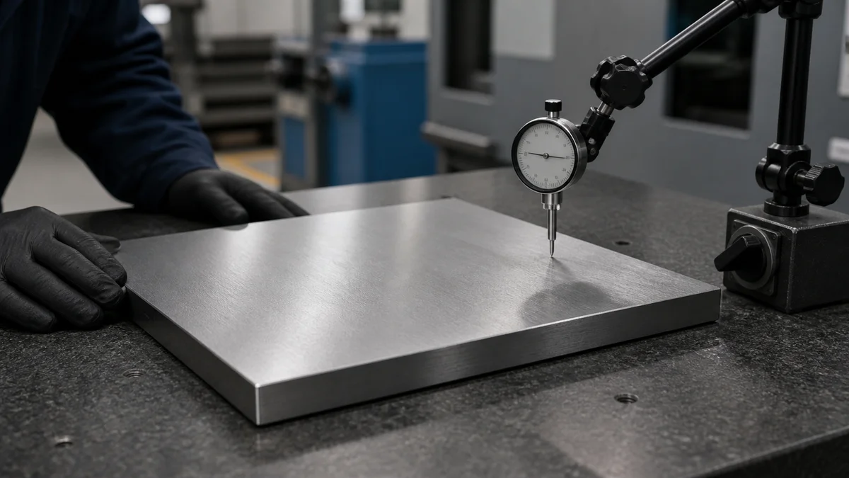
Surface grinding is a form-correction and finishing decision, not merely a way to erase milling marks. A face may satisfy its thickness limits yet remain unsuitable because it is tapered, bowed, locally uneven, or not parallel to the functional datum.
Review surface grinding when:
- A sealing face needs consistent contact rather than nominal thickness alone.
- A locating plane controls the orientation of another feature.
- A broad plate moves after unclamping or heat treatment.
- Tool deflection or interrupted cutting leaves local form variation.
- Two mating faces need a controlled parallel relationship.
- A flexible part produces different results when measured restrained and free.
Flatness controls one surface without a datum. Parallelism controls orientation relative to a specified datum. A tighter thickness tolerance does not replace either control; the drawing must express the condition that protects assembly, sealing, alignment, or load distribution.
Scenario: A rectangular plate is clamped flat during milling and passes an in-fixture thickness check. After release, residual stress allows it to bow. Before planning a critical flat face5, the buyer must state whether acceptance applies in the free state or under a defined assembly restraint. Stock condition, balanced material removal, grinding support, and inspection support may all need review.
Do not grind every face by default. Identify the functional face, its datum relationship, required roughness where relevant, and the manufacturing stage at which it must conform. This focuses secondary finishing and documented inspection on surfaces that actually determine performance.
Is the Part Geometry Suitable for Centerless Grinding?
Centerless grinding is most suitable for straight shafts, pins, and other continuously supported cylindrical parts that can feed through the process. Shoulders, flanges, interrupted surfaces, abrupt profile changes, and non-cylindrical features may limit or prevent its use, even when the diameter tolerance suggests grinding.
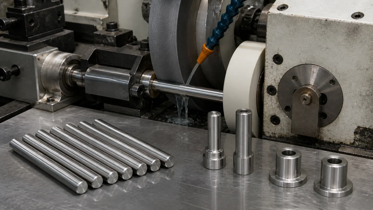
Centerless grinding supports the workpiece between a grinding wheel, regulating wheel, and work-rest arrangement rather than locating it between centers or holding it in a conventional chuck. This favors components with a compatible cylindrical path and enough continuity for stable support and feeding.
| Profile characteristic | Likely fit | Information the supplier needs |
|---|---|---|
| Straight pin or uniform shaft | Often suitable | Diameter, length, finish, and quantity |
| Long cylindrical feature | Potentially suitable | Straightness, stiffness, and feed stability |
| Shoulder or flange | Restricted | Transition location and alternative finishing options |
| Interrupted diameter | Restricted | Support continuity and wheel engagement |
| Flats, cross-holes, or non-round features | Case-dependent | Complete profile and operation sequence |
| Several related diameters | May require another method | Datum axis, runout, shoulders, and finish zones |
The supplier needs more than the smallest diameter. Provide the full turned profile, overall length, maximum and minimum diameters, shoulders, grooves, cross-holes, flats, threads, and every feature interrupting the grinding path. Identify critical size, roundness, cylindricity, straightness, and finish requirements separately.
Quantity and production intent also influence process fit. A prototype with a difficult shoulder may follow a different cylindrical finishing method from a stable repeat order of straight pins. Do not prescribe centerless grinding geometry6 from diameter tolerance alone; let the supplier assess the whole profile and its datum relationships.
Inspection must also distinguish size from roundness, cylindricity, straightness, and finish. One acceptable diameter reading does not verify those other functional characteristics.
Does the Part Need Form Control Beyond a Size Tolerance?
Specify form separately when function depends on roundness, cylindricity, flatness, parallelism, or taper rather than size alone. Evaluate grinding when milling or turning can reach the nominal dimension but may leave form error that affects bearing preload, sealing, alignment, contact, or load distribution.
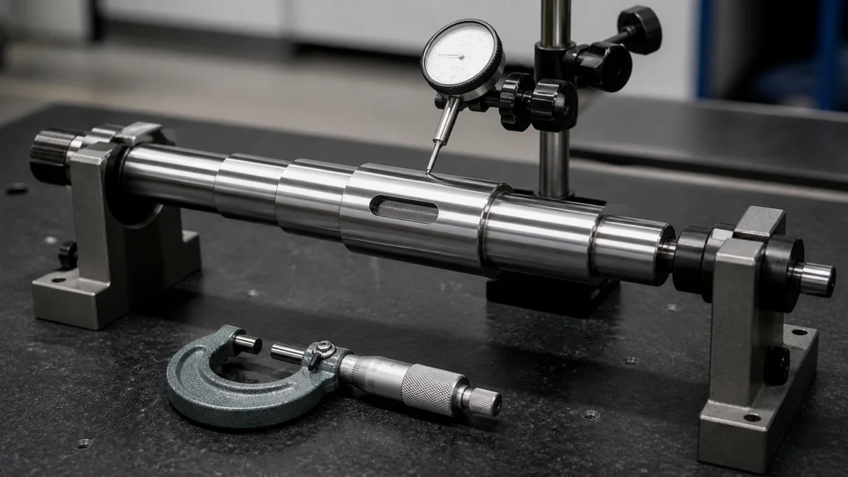
Size and form answer different inspection questions. A diameter tolerance defines the permitted size range, but it does not necessarily establish how round each section is or how cylindrical the full surface must be. A thickness tolerance controls size between opposed surfaces, not the flatness of either face or its orientation to a datum.
Assemblies respond to the actual contacting geometry. A bearing journal can remain within diameter limits while taper or roundness error changes bearing contact. A sealing face can pass thickness inspection while local form error prevents full contact. A locating plate can meet size requirements and still fail parallelism to its mounting datum.
Which control protects the function?
- Use roundness for individual circular sections.
- Use cylindricity for the complete cylindrical surface.
- Use flatness for one surface independent of a datum.
- Use parallelism for orientation relative to a defined datum.
- Use size tolerance for the allowable feature dimension.
A common mistake is shrinking a plus-or-minus size tolerance to solve every geometric concern. That expands machining and inspection while leaving the actual failure mode unclear. Define size and form control independently7 so the supplier knows whether grinding must correct diameter, surface geometry, datum orientation, or a combination.
Where relationships matter, establish functional datums and identify the geometric results that require documentation after grinding. Inspection must reproduce the specified datum structure and delivered condition. For flexible parts, state whether measurement occurs free, restrained, after thermal stabilization, or after another final process. Grinding has specification value only when the targeted error and its acceptance method are both clear.
How Should Grinding Allowance and Datums Be Planned?
Plan grinding allowance, datums, and process sequence before CNC roughing begins. Retain intentional stock only on designated ground surfaces, preserve accessible functional references through heat treatment, and state the final size, geometric control, roughness, inspection condition, and position of grinding among all secondary operations.
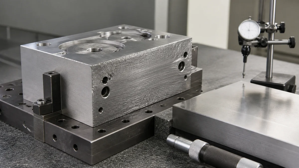
Grinding allowance is the material intentionally retained for final finishing. It must be sufficient to clean up expected machining or heat-treatment variation, but it should not come from an unsupported universal value. Material grade, hardness, surface area, section thickness, distortion risk, geometry, and grinding method all affect the appropriate amount.
Use this planning check before rough machining:
- Mark every face and diameter that will be ground.
- Define each final dimension and tolerance.
- Separate size from flatness, parallelism, roundness, cylindricity, or runout.
- Establish accessible functional datums for grinding and inspection.
- State incoming and final material conditions.
- Place heat treatment correctly in the operation sequence.
- Clarify whether coating, plating, passivation, or another finish occurs before or after grinding.
- Define roughness values, units, zones, and measurement locations.
- State the free-state or restrained acceptance condition where relevant.
- Define first-article, sampling, and final-report expectations.
Datum transfer deserves special attention. If rough machining locates from a convenient setup face but final inspection references another functional face or axis, every transfer can add alignment uncertainty. The grinding supplier must understand how the part locates in assembly and which reference controls the finished feature.
A frequent specification error is leaving machining stock8 undefined while prescribing final grinding. Excess stock can increase removal and heat; insufficient stock may not clean up distortion. The RFQ should identify responsibility for selecting the allowance and provide the geometry, thermal route, and final controls needed for that decision.
When Should You Leave a Feature As Machined?
Leave a feature milled or turned when its functional tolerance, form, and surface finish can be met reliably without a separate grinding operation. Requirements around ±0.05 mm or Ra 1.6–3.2 µm may often remain machined, subject to material, geometry, supplier capability, quantity, and inspection needs.
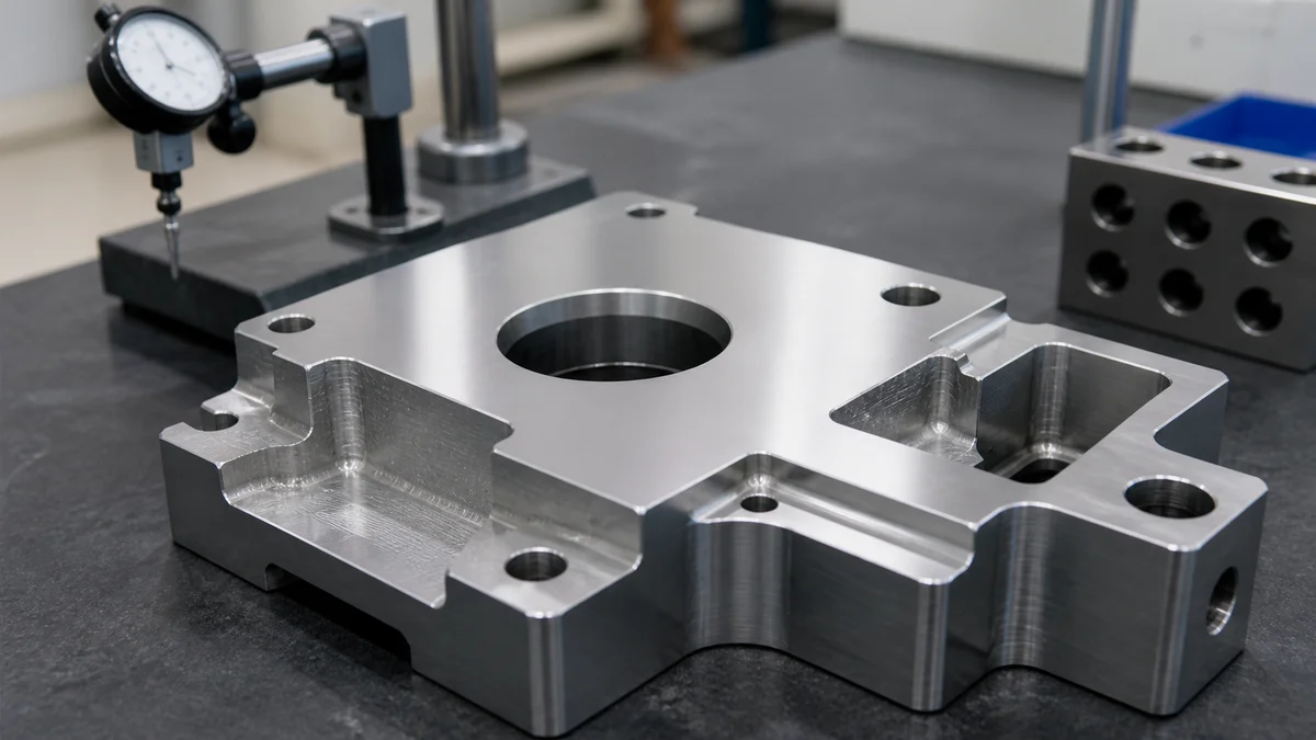
Grinding should solve a defined manufacturing problem, not act as a general signal of quality. Each additional ground surface adds handling, setup, datum transfer, process coordination, and inspection.
The reference values are planning guides rather than universal capability promises. A rigid, accessible feature around ±0.05 mm may be straightforward to machine, while a broad thin plate with the same tolerance may move after unclamping. Likewise, Ra 1.6–3.2 µm may be attainable on an open face but more difficult inside a narrow or interrupted feature.
| Feature category | Useful specification | Recommended decision |
|---|---|---|
| Bearing, sealing, or wear interface | Explicit size, form, and finish | Review grinding where function requires it |
| Alignment or mating feature | Datum-based relationship and inspection | Review the complete setup plan |
| Clearance pocket | General or looser control | Usually leave machined |
| Cosmetic edge | Appearance and edge condition | Grinding is rarely the direct solution |
| Non-contact surface | Ordinary machined condition | Avoid unnecessary secondary finishing |
A common mistake is adding “grind all surfaces” to avoid classifying critical features. That note can conflict with edges, threads, holes, thin walls, and datum features. It can also demand material removal where no allowance exists.
Instead, use selective finish callouts9 and classify features as functional, assembly-related, cosmetic, or noncritical. Apply grinding only where final size, geometric form, fine roughness, or post-treatment correction supports the intended function. This gives the supplier room to propose an efficient, stable, and inspectable route.
What Should a Grinding-Ready RFQ Include?
A grinding-ready RFQ must define the complete manufacturing route, not merely request a ground part. Send matching model and drawing revisions, exact material condition, controlled surfaces, tolerances, GD&T, roughness, grinding allowance, datums, heat treatment, quantity, production intent, inspection evidence, and delivery expectations.
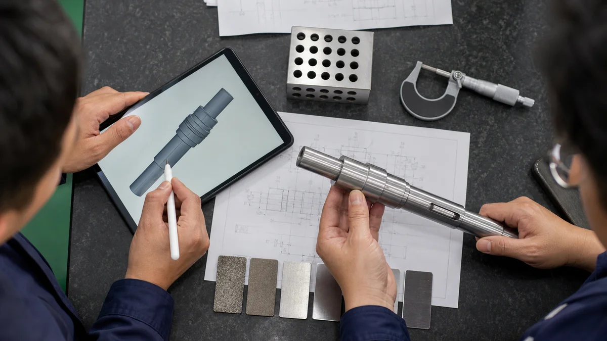
Use this complete RFQ checklist10 before requesting a process recommendation, sample, or quotation:
- ☐ Current 3D CAD model showing the complete geometry.
- ☐ Controlled 2D drawing with part number, units, active revision, and governing notes.
- ☐ Statement identifying which document controls if the model and drawing conflict.
- ☐ Exact material grade, incoming condition, and required final condition.
- ☐ Immediate quantity and prototype, pilot, or repeat-production intent.
- ☐ Projected lot pattern or annual usage when known.
- ☐ Every ground face and diameter marked individually.
- ☐ Grinding purpose identified as size, form, roughness, post-treatment correction, or a defined combination.
- ☐ Critical size tolerances separated from ordinary dimensions.
- ☐ Applicable GD&T controls and functional datums.
- ☐ Roughness parameter, value, units, zones, and measurement locations.
- ☐ Heat-treatment route and target hardness where applicable.
- ☐ Responsibility for determining the machining allowance.
- ☐ Sequence for coatings, plating, passivation, or other secondary operations.
- ☐ Free-state or restrained measurement condition where relevant.
- ☐ First-article, sampling, final-report, or selected full-inspection requirements.
- ☐ Delivery expectations and permission to propose another finishing route where function allows.
Name the primary process correctly. CNC machining removes material through milling, turning, drilling, boring, and reaming. CNC turret punching and CNC punch press work use programmed tools on sheet metal. Metal stamping uses dedicated dies; CNC-controlled stamping equipment describes machine control, not one universal process. Sheet metal fabrication may include cutting, bending, punching, welding, and finishing. Plastic injection molding forms polymer in a mold.
“CNC turret punching, CNC punch press, CNC-controlled stamping equipment, or metal stamping depending on the actual process” is not a standard process term. Clarify whether purchasing data means CNC turret punching, punch press work, CNC-controlled die stamping, or general metal stamping before requesting a grinding quotation.
For a grinding recommendation, sample, or quotation, send the 3D model, controlled 2D drawing, material grade and condition, quantity, prototype or production intent, marked grinding surfaces, critical tolerances, finish requirements, inspection expectations, active revision, and delivery needs.
References
-
Length and Dimensional Measurements at NIST - PMC - by DA Swyt · 2001 · Cited by 52 — This paper discusses the past, present, and future of length and dimensional measurements at NIST. achievable machining tolerances for particular classes of ... ↩
-
Control of Distortion in Tool Steels - ASM Digital Library - It explains the various factors considered to control distortion in tools steels, namely, design, initial condition, machining procedure, and heat treatment. ↩
-
The surface integrity of turned and ground hardened ... - by AM Abrāo · 1996 · Cited by 257 — The paper compares several aspects of finish turning against grinding of hardened bearing steel, more specifically surface texture, microstructural alterations, ↩
-
Understanding ISO 21920 Surface Roughness Standards - ISO 21920 marks a significant improvement in how surface roughness is defined, measured, and communicated. By aligning with international ... ↩
-
ASME Y14.5 2018 – Key Terms and Definitions Explained - → 3.37 Flatness: Surface lies in a single plane. → 3.38 Free State: Part in natural shape without external force. → 3.39 Interruption: Break ... ↩
-
'Pain-Free' Precision with Centerless Grinding - SME.org - Once a centerless grinder is set up for a specific part, the operator needs to make only minimal adjustments to maintain the OD size. ↩
-
GD&T Rule #1: Envelope Principle - The ASME Y-14.5 applies Rule #1 by default to all features of size. Flatness or Straightness. Symbols that typically refine form are ... ↩
-
Heat Treatment of Metals: Types & CNC Machining Effects - Stock allowance: Pre-plan extra material for finish passes according to part geometry and treatment method. Typical allowances: 0.3–1 mm for ... ↩
-
Surface finish callout: How to read and specify them on ... - A surface finish callout is an ISO standardized drawing symbol system used to define the required condition of a surface after manufacturing. ↩
-
OEM CNC Machining RFQ Guide: 10 Costly Mistakes ... - Material specifications should never be assumed. Surface finish requirements should be clearly defined. reviewing drawings, tolerances, ... ↩