
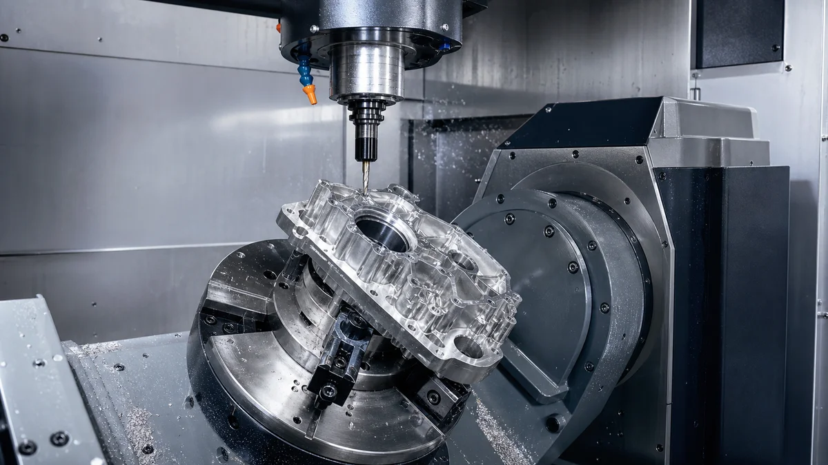
Five-axis CNC machining becomes valuable when part geometry, cutter access, or critical relationships across several faces make conventional setups difficult to control. It is not automatically the right choice for every part described as complex. Many plates, brackets, housings, and fixed-angle features remain suitable for 3-axis or indexed 3+2 machining.
Start with the 3D geometry and controlled drawing. Review access directions, functional datums, tolerances, surface finish, material grade, wall thickness, inspection scope, quantity, revision stability, and production intent. Together, these requirements show whether rotary motion reduces manufacturing risk or merely adds programming and verification work.
The decisions below provide a practical framework for choosing an axis configuration, correcting specification gaps, and preparing an RFQ that allows suppliers to compare viable process plans.
Should You Use 3-Axis, Indexed 3+2, or Simultaneous 5-Axis Machining?
Use 3-axis machining for accessible prismatic features, indexed 3+2 machining for fixed-angle or multi-face work, and simultaneous 5-axis machining when cutter orientation must change continuously. Select the simplest configuration that reaches every feature while supporting the specified tolerances, finish, and inspection plan.
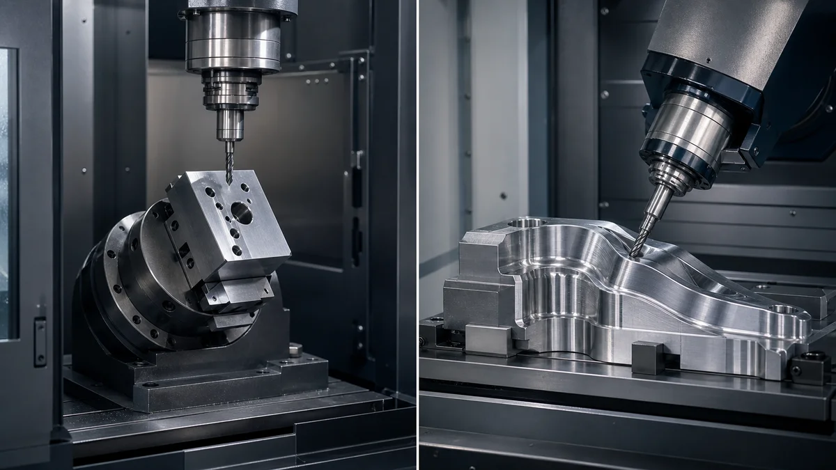
Five-axis machining coordinates three linear axes with two rotary axes. The operating mode matters because indexed positioning and simultaneous motion solve different manufacturing problems. Authoritative rotary-axis machining terminology1 can help design and purchasing teams describe the intended motion consistently.
In indexed 3+2 machining, the rotary axes position the workpiece at a selected angle and remain locked while cutting occurs. This suits holes, bores, pockets, and planar faces located on several sides or at fixed non-orthogonal angles. Simultaneous 5-axis machining moves the linear and rotary axes together so the cutter can follow continuously changing surface orientation.
| Configuration | Suitable feature pattern | Cutter orientation during cutting | Drawing evidence needed |
|---|---|---|---|
| 3-axis | Plates, brackets, open pockets, accessible housings | Fixed | Features reachable from standard directions |
| Indexed 3+2 | Multi-face holes, angled bores, fixed-angle faces | Indexed, then locked | Feature axes and fixed angles |
| Simultaneous 5-axis | Free-form surfaces and continuous contours | Changes continuously | Controlled contour and surface relationships |
A visually intricate model does not necessarily need simultaneous motion. Repeated holes on angled faces may look complex but still fit indexed machining. Conversely, a smooth-looking surface may require simultaneous motion when its curvature changes throughout the toolpath.
Example: A housing has top pockets and fixed-angle ports on two side faces. Indexed 3+2 machining may reach every feature without continuous rotary movement. Prescribing simultaneous 5-axis machining would add programming and verification without addressing another stated requirement.
When Does Restricted Tool Access Justify 5-Axis Machining?
Restricted access can justify 5-axis machining when compound angles, undercuts, angled bores, hidden pockets, or free-form surfaces cannot be reached efficiently from standard directions. The decision should come from a documented tool-access review that also considers workholding, fixture clearance, and inspection access.
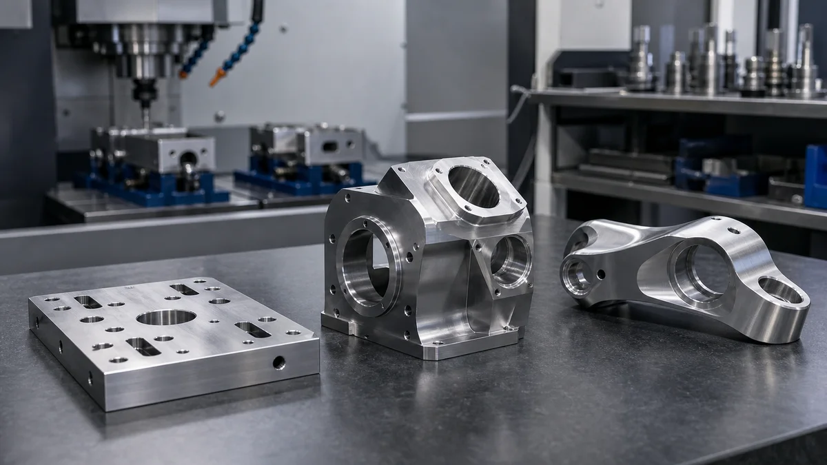
Tool access is more specific than general geometric complexity. The review must determine whether a cutter can reach each required surface with a practical diameter, cutting length, holder clearance, and approach direction. The workpiece, holder, spindle, and fixture must remain clear as the rotary axes reposition, making five-axis collision avoidance2 part of process planning.
Check the model and drawing for:
- Features that cannot be reached along standard orthogonal directions.
- Undercuts or internal transitions hidden in ordinary drawing views.
- Angled bores whose axes must align with mating components.
- Surfaces requiring uninterrupted contouring rather than separate indexed cuts.
- Regions where the holder or spindle may interfere with nearby walls.
- Fixture geometry that obstructs the required rotary position.
- Features that are machinable but inaccessible to the planned inspection method.
The 3D model communicates the complete form, while the controlled 2D drawing carries tolerances, datums, finish zones, and inspection requirements. Add section or detail views for blind pockets, internal radii, undercuts, and angled interfaces. These views should reveal depth and functional relationships without dictating an unsupported toolpath.
Can a special fixture replace 5-axis machining?
Sometimes. A stable part with only a few fixed orientations may suit separate fixtures or angled workholding. That route becomes less attractive when fixture changes multiply, datum transfer threatens cross-face relationships, or expected revisions would require repeated fixture changes.
A common specification mistake is writing “5-axis required” without identifying inaccessible surfaces. Mark feature directions and functional relationships instead, then let the supplier compare fixtures, indexed 3+2 machining, simultaneous motion, or a geometry revision.
When Do Cross-Face Tolerances Benefit from One 5-Axis Setup?
Cross-face tolerances may benefit from one 5-axis setup when functional features on several faces share controlled position, angularity, perpendicularity, or profile relationships. One clamping can reduce datum-transfer risk, but the drawing must identify the relationships that matter rather than applying tight tolerances everywhere.
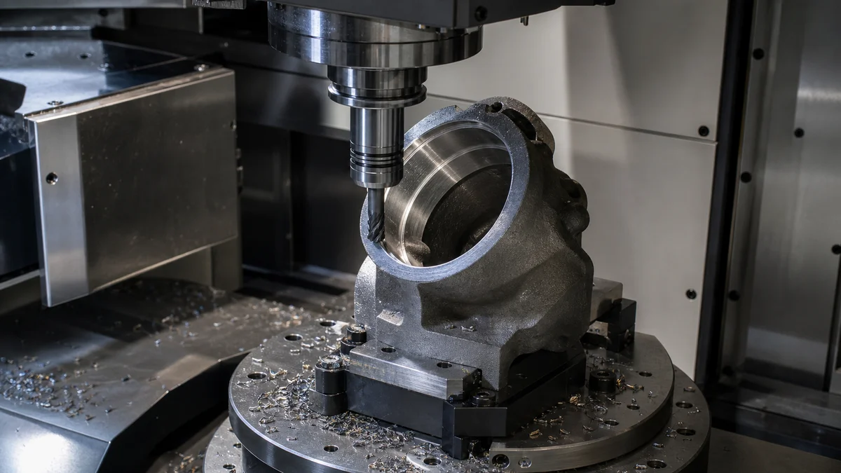
Removing and repositioning a part requires the manufacturing plan to re-establish its reference system. A controlled multi-setup route can still be appropriate, but each datum transfer introduces another source of alignment variation. The practical question is whether the affected features control fit, sealing, alignment, or performance.
A mounting face might establish datum A, a bore datum B, and a locating feature datum C. Together, they form the datum reference frame3 used to locate angled ports, side holes, and mating faces. Machining those features without releasing the workpiece may simplify control of their relationships. This matters more than a tight tolerance on an isolated pocket depth or cosmetic edge.
The drawing should distinguish:
- Functional features: bearing bores, sealing faces, dowel holes, aligned ports, and mating interfaces.
- Assembly-related features: clearance holes, mounting faces, and locating geometry needed for installation.
- Non-critical features: lightening pockets, cosmetic edges, and non-contact surfaces that do not need the same control.
Use GD&T when size alone does not express function. Position controls location relative to datums; perpendicularity and angularity control orientation; profile can control a complex surface relative to the established references. Avoid tightening every size dimension merely to imply precision.
One clamping does not guarantee conformance. Tool deflection, material movement, thermal conditions, workholding, surface finish, and inspection method still affect the result. Select 5-axis machining when a common setup meaningfully protects identified cross-face relationships, not simply because features appear on several sides.
Can 5-Axis Machining Improve Access to Deep Cavities and Pockets?
Five-axis machining can improve deep-feature access when tilting the workpiece provides a more direct approach and permits shorter, more rigid tooling. Feasibility still depends on cavity depth, opening size, internal radii, surrounding walls, chip evacuation, holder clearance, and the surfaces requiring close control.
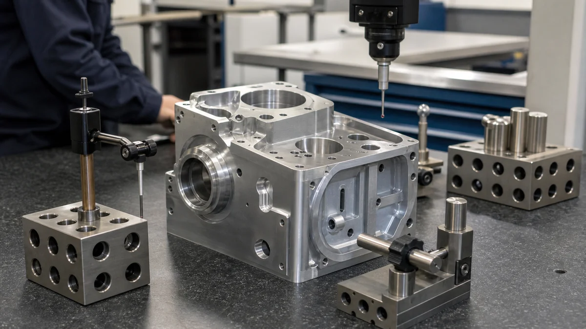
A fixed vertical approach may force a cutter to extend far beyond its holder. As overhang increases, rigidity falls and the process becomes more exposed to deflection, chatter, chip recutting, poor surface generation, and dimensional drift. Tilting the workpiece can sometimes create a shorter, more direct approach to a pocket wall or floor.
Evaluate the cavity as a connected system:
- Opening size: The cutter and holder need clearance to enter and move without collision.
- Internal radii: Small corner radii require smaller cutters, which become less rigid at long reach.
- Depth and wall angle: These determine whether tilting improves access or merely relocates interference.
- Surrounding geometry: Bosses, ribs, and adjacent walls may block the preferred approach.
- Chip path: A reachable feature remains risky if chips cannot leave the cutting zone.
- Fixture clearance: Rotary movement must not bring the part, holder, or spindle into the workholding.
Published deep-pocket machining guidance4 can support a design review, but general ratios should be treated as DFM references rather than universal machine limits. The actual decision depends on cutter diameter, tool length, material, finish, tolerance, and supplier strategy.
Localize requirements within the cavity. If only one lower sidewall is a sealing surface, apply its tolerance and surface-finish requirement there rather than across every clearance surface. This gives the supplier room to use a stable roughing and finishing sequence.
Five axes cannot create a perfectly sharp internal corner with a cylindrical cutter or pass a holder through an undersized opening. Increasing an internal radius, opening an access region, or dividing the component may be the better correction.
When Do Thin Walls or High-Risk Materials Favor 5-Axis Machining?
Thin walls or high-risk materials may favor 5-axis machining when improved approach angles reduce tool reach, handling, or difficult workholding. Neither condition is sufficient alone. Material grade, wall proportions, support, cutting access, finish, quantity, and post-machining operations must be evaluated together.
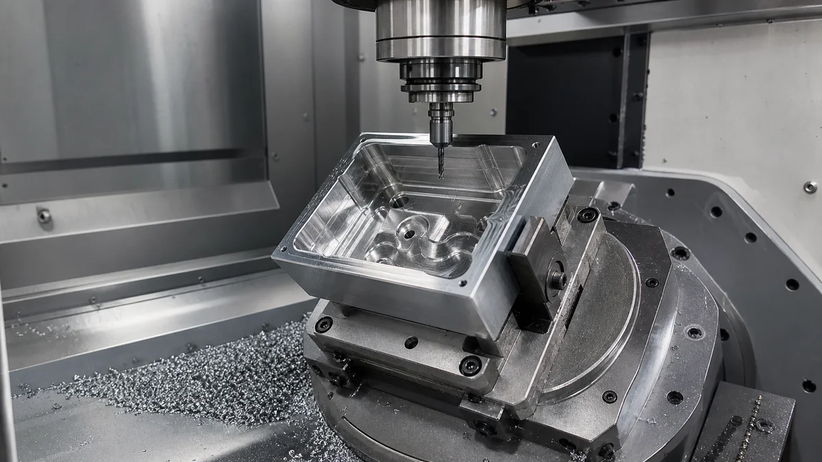
Thin walls lose stiffness as surrounding stock is removed. Cutting force and concentrated clamping pressure may cause vibration, temporary deformation, or movement after release. Changing cutter orientation can improve access and tool engagement, but it cannot make an unsupported wall rigid. Thin-wall machining stability5 still depends on wall height, thickness, support, workholding, tool reach, material condition, and cutting sequence.
Costly or difficult-to-machine stock changes the risk calculation because each additional setup creates another handling and alignment event. Fewer setups may reduce that exposure, particularly after substantial machining value has already accumulated in the part. The proposed single setup must still provide secure clamping and practical cutter access.
| Specification factor | Possible 5-axis benefit | Risk that remains |
|---|---|---|
| Thin wall or rib | More direct cutter approach | Vibration, wall movement, clamp distortion |
| Restricted clamping area | Fewer repositioning events | Too little stable material for initial workholding |
| Difficult material | Less handling between operations | Tool wear, heat, chip control, and finish remain material-dependent |
| Costly stock | Fewer setup-transfer opportunities | More completed work may be concentrated in one part |
| Secondary treatment | Consolidated machining sequence | Coating, heat, or residual stress may alter final dimensions |
State the exact material grade and condition rather than “aluminum,” “stainless,” or “alloy.” Mark minimum wall sections, wall height, no-clamp zones, functional surfaces, and the required measurement condition. If anodizing, plating, heat treatment, or another secondary operation follows machining, specify whether critical dimensions apply before or after that step.
Allow the supplier to compare sacrificial supports, revised workholding, indexed positioning, simultaneous motion, or a geometry change. Axis count is only one element of the stability plan.
Should a Multi-Piece Assembly Become One 5-Axis Machined Part?
Consolidate an assembly into one 5-axis machined part only when removing fasteners and inter-part tolerance stack-up creates enough functional value to justify harder machining, inspection, material use, and replacement. Every combined interface must remain accessible, inspectable, and necessary.
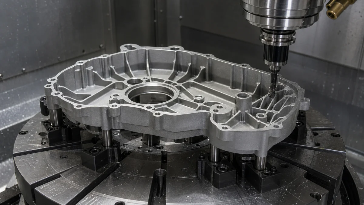
A monolithic component can preserve relationships between angled bores, mounting faces, ports, and other interfaces without relying on separate parts and fasteners. Consolidation also transfers assembly complexity into machining complexity. A nonconforming feature can affect the entire component, and internal geometry may become harder to reach or measure.
| Specification decision | One machined part | Simpler joined parts |
|---|---|---|
| Critical alignment | Features may share one datum system | Alignment includes component and assembly tolerances |
| Cutter access | May require multi-axis approaches | Individual parts may provide open access |
| Inspection | Relationships are verified within one component | Parts can be inspected separately before assembly |
| Material use | More stock may need removal | Stock can match each simpler envelope |
| Service strategy | Whole component may require replacement | Individual parts may remain replaceable |
| Design revision | One model controls all interfaces | A revision may affect fewer components |
Scenario: A design team is considering combining a machined aluminum housing, angled port block, and mounting interface. This is a teaching scenario, not a customer case. A design for manufacturing review6 should identify which alignments currently depend on assembly, whether the internal ports remain machinable and inspectable, and whether removing the fasteners provides enough functional value.
If the housing may later move to die casting or plastic injection molding, review that future process separately. Die casting and molding introduce tooling-dependent requirements such as wall consistency, corner radii, draft, fastening details, and cosmetic surfaces. Injection molding also requires review of gate location because polymer flow and visible gate vestige affect the molded design. A machined prototype does not automatically represent casting or molding geometry.
When the answer is uncertain, request two options: a consolidated part and a controlled multi-piece assembly.
How Should GD&T and Inspection Be Planned for a 5-Axis Part?
Plan GD&T and inspection together by defining functional datums, controlled relationships, measurement conditions, reporting scope, and inspection frequency before quotation. A single 5-axis setup may reduce datum transfer during machining, but it does not prove that specified position, orientation, profile, or surface requirements were achieved.
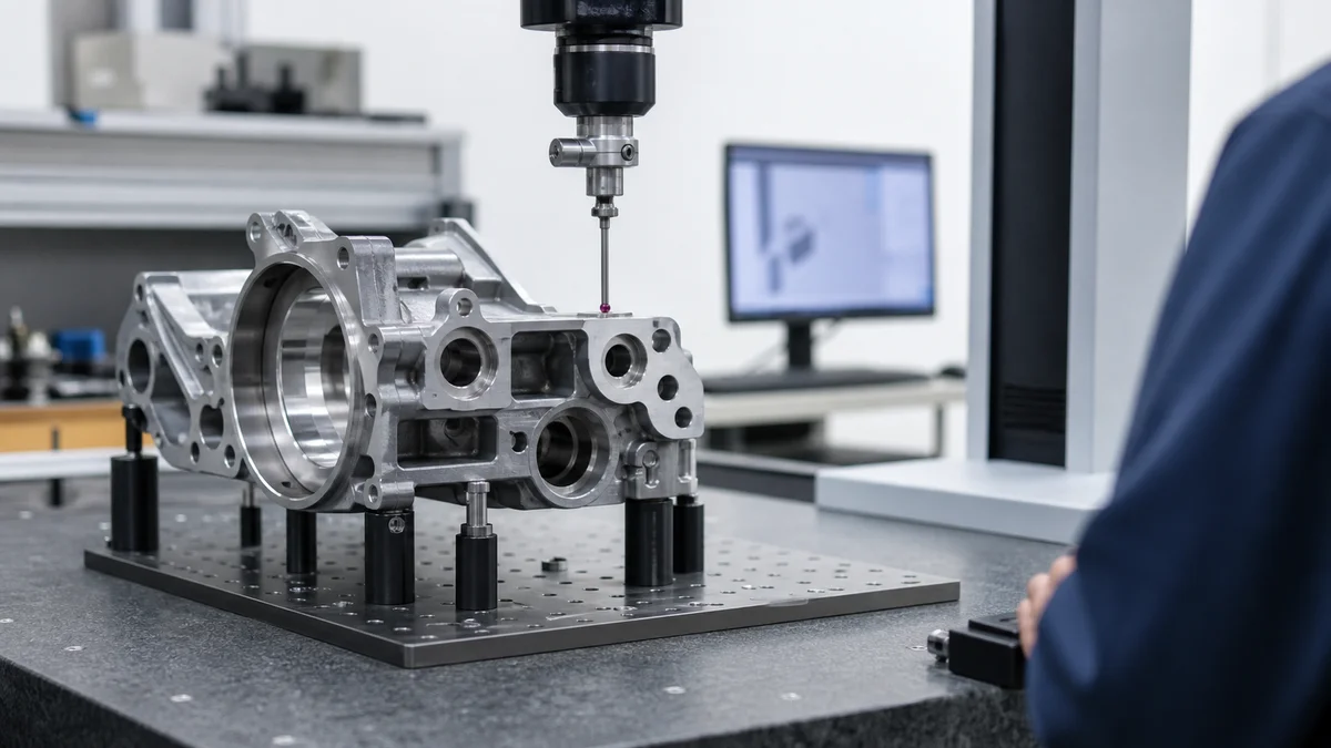
Geometric dimensioning and tolerancing principles7 are most useful when they express how features function together. Position may control a hole pattern relative to datums; perpendicularity or angularity may control cross-face orientation; profile may define a free-form surface. The datum scheme should reflect how the part locates in assembly and provide accessible inspection references.
Before drawing approval, confirm:
- Are the primary, secondary, and tertiary datums stable, accessible, and functionally relevant?
- Which features need only size verification, and which require form, orientation, or location control?
- Which surfaces are functional, assembly-related, cosmetic, or non-critical?
- Can the planned inspection method reach controlled curves, deep pockets, and angled features?
- Do flexible walls require an agreed restrained or unrestrained measurement condition?
- Does inspection occur before or after anodizing, plating, heat treatment, or another secondary operation?
- Could finish buildup affect a tolerance-critical bore, mating face, or threaded feature?
- Is first-article inspection required for the supplier’s initial production run?
- Are final dimensional results, batch sampling, or checks on every selected critical feature required?
- What report format and acceptance criteria must accompany delivery?
Does first-article approval prove process capability?
No. A conforming first article verifies the inspected sample against the applicable requirements at that time. It does not establish that every later part will conform. Specify ongoing sampling, in-process controls, or other capability evidence separately when production risk requires them.
A frequent specification error is applying profile control to every modeled surface. That expands machining and inspection scope while obscuring the zones that protect fit, sealing, alignment, or performance.
When Does 5-Axis Machining Reduce Total Cost or Lead Time?
Five-axis machining may reduce total cost or lead time when fewer fixtures, setups, alignments, and intermediate inspections offset its additional programming, simulation, and verification effort. Compare complete process plans using actual geometry, quantity, material risk, revision stability, inspection scope, and delivery requirements.
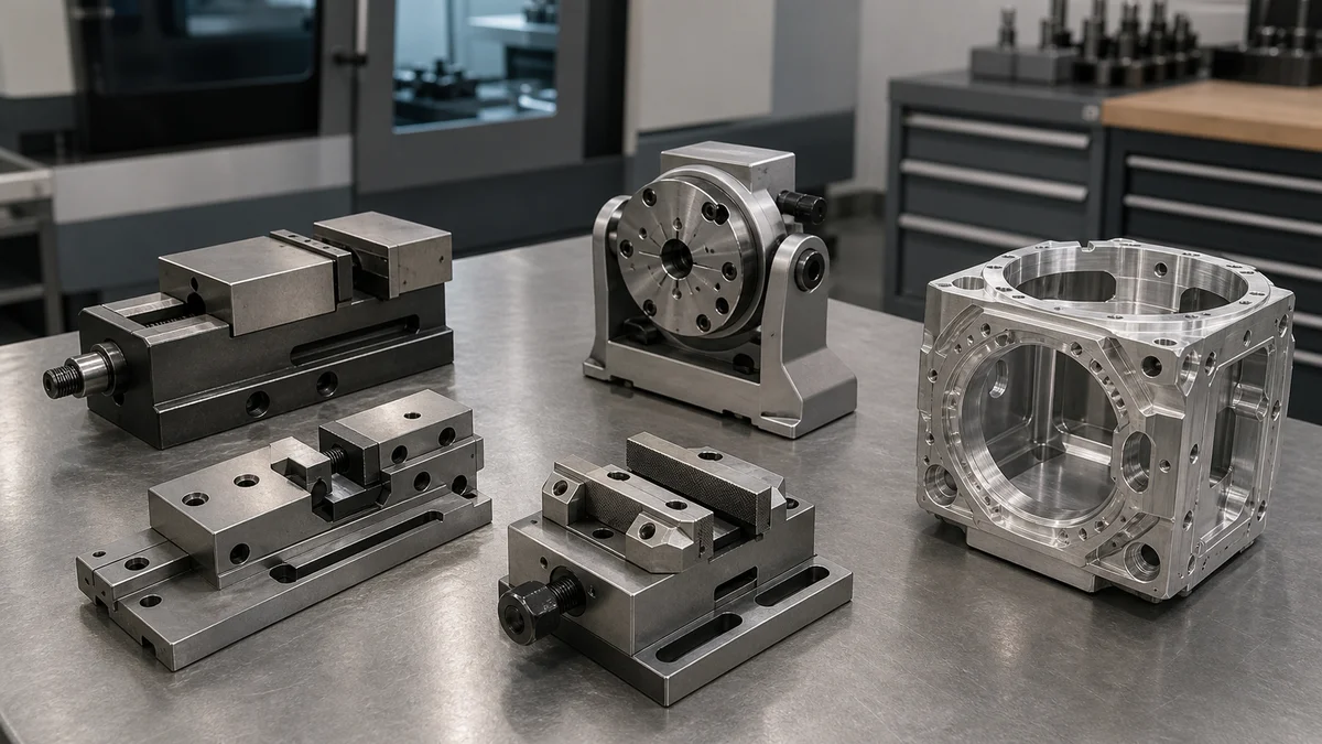
Machine rate alone does not describe the manufacturing plan. A 3-axis route may need several fixtures, repeated part location, separate programs, intermediate checks, and manual handling. A 5-axis route may consolidate those activities while requiring more demanding toolpath preparation and collision review. Sound manufacturing cost estimation8 includes both sets of work.
| Cost or schedule input | Multi-setup 3-axis route | 5-axis route |
|---|---|---|
| Programming | Several simpler operations may be prepared | Rotary motion and collision review may add complexity |
| Workholding | Separate or adjustable fixtures may be required | One primary fixture may expose more faces |
| Reorientation | Manual handling and datum transfer recur | Rotary positioning may occur without unclamping |
| Inspection | Intermediate checks may establish later setups | Complex final relationships still need verification |
| Revision exposure | Dedicated fixtures may require changes | Flexible positioning may reduce fixture changes |
| Material exposure | Error may be introduced at each setup | More operations may be concentrated in one clamping |
Prototype and repeat-production intent should be quoted separately. A frequently revised prototype may benefit from flexible workholding because several dedicated fixtures carry revision risk. A stable repeat part may justify optimized fixtures, batching, or a simpler machine route. Quantity determines how programming and fixture preparation are distributed across the order.
Example: A multi-sided prototype is expected to change during design validation. The useful comparison is not one hourly machine rate against another. It is the total effort to update programs and fixtures, relocate the revised part, machine every orientation, verify critical relationships, and meet the requested delivery sequence.
Where geometry permits more than one route, ask for process-plan alternatives with their setup, inspection, and revision assumptions stated.
What Specification Problems Cannot Be Solved by 5-Axis Machining?
Five-axis machining cannot correct ambiguous datums, conflicting model and drawing data, blanket tolerances, undefined finish zones, inaccessible inspection features, or an incorrect process specification. Resolve these issues first, then let the supplier recommend 3-axis, indexed 3+2, simultaneous 5-axis, or a design revision.
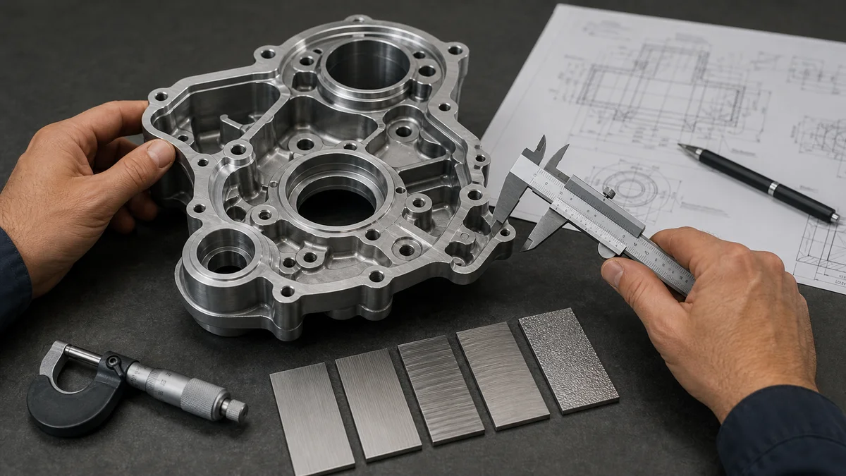
Additional machine motion cannot replace clear product requirements. The supplier still needs to know which document controls, how the part functions, what must be measured, and which features may remain at ordinary machining conditions. Consistent engineering drawing requirements9 should be established before process selection.
Use this pre-approval review:
- Model and drawing agreement: Confirm geometry, units, part number, and active revision. State which document governs if differences remain.
- Functional datums: Select accessible references that represent assembly location rather than convenient drawing edges.
- Tolerance hierarchy: Separate functional, assembly-related, cosmetic, and non-critical features.
- Complete GD&T: Define datums and feature control frames wherever position, orientation, form, or profile controls function.
- Local surface finish: Mark sealing, sliding, bearing, coating-preparation, and cosmetic zones instead of applying one fine finish everywhere.
- Secondary operations: State whether dimensions apply before or after coating, heat treatment, finishing, or assembly.
- Inspection access: Confirm that critical internal or angled features can be measured under an agreed condition.
- Process flexibility: Specify the required final characteristics while allowing a justified manufacturing recommendation.
One common mistake is prescribing simultaneous 5-axis machining when the drawing contains only fixed-angle holes and planar faces. That instruction can prevent a supplier from proposing indexed 3+2 machining even when it satisfies the functional requirements.
Another mistake is assuming one clamping guarantees every tolerance. Workholding, material movement, tool reach, thermal conditions, surface finish, finish buildup, and inspection method remain relevant. A process name should follow a controlled specification, not compensate for missing product definition.
What Should a Complete 5-Axis CNC Machining RFQ Include?
A complete 5-axis RFQ should define the intended process and provide the model, controlled drawing, material grade, quantity, production intent, critical tolerances, finish, inspection requirements, revision, and delivery expectations. These inputs let the supplier select an appropriate axis configuration and quote the complete manufacturing plan.
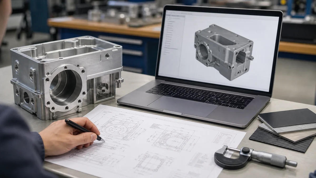
First confirm that the request concerns CNC machining, which removes material through milling, turning, drilling, boring, reaming, or related operations. It is not interchangeable with a sheet metal or molding process. Clear request for quotation requirements10 prevent suppliers from pricing different assumptions.
CNC turret punching or CNC punch press work uses programmed punch tools on sheet metal. Its specification may need sheet thickness, hole geometry, formed features, and burr direction. Metal stamping uses dedicated dies to cut or form sheet and may require consideration of burr direction and springback. Sheet metal fabrication can combine cutting, punching, bending, welding, and finishing. Plastic injection molding forms polymer in a mold and introduces separate concerns such as draft, gate location, wall consistency, and tooling. “CNC turret punching, CNC punch press, CNC-controlled stamping equipment, or metal stamping depending on the actual process” is not one standard process term; clarify whether it means turret punching, CNC-controlled stamping equipment, or general metal stamping.
RFQ checklist
- 3D CAD model showing complete geometry.
- Controlled 2D drawing with units, part number, and active revision.
- Statement identifying which document controls if the model and drawing differ.
- Exact material grade and condition, plus permitted alternatives.
- Immediate quantity and projected usage when known.
- Prototype, validation, pilot, or repeat-production intent.
- Functional datums and critical cross-face relationships.
- Size tolerances and GD&T applied where function requires them.
- Identification of functional, assembly-related, cosmetic, and non-critical features.
- Local surface-finish requirements and defined finish zones.
- Deburring, edge, coating, heat-treatment, masking, and assembly requirements.
- Statement of whether dimensions apply before or after secondary operations.
- Inspection method, measurement condition, sampling frequency, and required reports.
- First-article requirements when applicable.
- Delivery expectations and partial-shipment needs.
- Permission for DFM feedback and alternative 3-axis, 3+2, or simultaneous 5-axis plans.
These inputs let suppliers quote geometry, tooling, setup, inspection, material, and schedule on a common basis.
For a process recommendation or quotation, send the 3D model, controlled 2D drawing, material grade, quantity, prototype or production intent, critical tolerances, surface finish, inspection expectations, revision level, and delivery requirements. Mark restricted access and cross-face relationships so the supplier can compare 3-axis, indexed 3+2, and simultaneous 5-axis plans.
References
-
3+2 vs. Simultaneous 5-Axis Machining: Which Approach Fits Your ... - Simultaneous 5-axis machining involves all five axes (three linear and two rotary) moving at the exact same time during the cutting cycle. As the cutting tool ... ↩
-
5 Axis CNC Milling Steel: Avoid Tool Holder Collisions - Simply put: a tool holder collision means the shank, collet nut, or spindle housing hits the part, the fixture, or the machine table. ↩
-
The Datum Reference Frame | GD&T Basics - The datum reference frame is the coordinate system created by the datums specified within a feature control frame. ↩
-
Deep Pocket Milling: Trochoidal vs Adaptive Toolpaths - RivCut - Chip Evacuation Chips are the number one killer of deep pocket operations. Worn tools deflect more. More deflection means worse finish and broken tools. It is ... ↩
-
Thin Wall CNC Machining: Process, Deformation & Cost - JLCCNC - Thin-wall CNC machining is primarily a structural stability problem rather than a simple material-removal problem. When the wall thickness is ... ↩
-
Tolerance in Product Design: How to Avoid Stack-Up Nightmares ... - Tolerance stack-up represents one of the most overlooked aspects of product design, yet it directly impacts manufacturability, assembly time, ... ↩
-
ASME Y14.5-2018 vs. 2009: Changes & Latest GD&T Standards - The standard recommends the use of geometric tolerancing symbols of position, profile, orientation, and runout tolerances as the proper way to define ... ↩
-
Technical Guide: Machining Cost | Precision CNC Machining - Fixed costs represent the foundational expenses incurred at the start of a CNC machining project; these costs primarily include setup and programming. ↩
-
ISO vs ASME Technical Drawing Standards: Com… | Werk24 Blog - This comprehensive guide compares ISO and ASME technical drawing standards across all major aspects: dimensioning, tolerancing, GD&T symbols, ... ↩
-
RFQ Checklist: What to Include for Faster Quotes | MakerStage - A manufacturing RFQ includes the 3D model, 2D drawing, material specification, quantity, lead time, tolerance requirements, surface finish, and inspection level ... ↩