
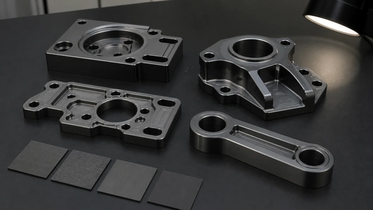
Cosmetic quality on a CNC machined part cannot be controlled by the 3D model alone. As-machined surfaces normally retain cutter paths, while terms such as “smooth,” “clean,” and “no tool marks” fail to identify which faces matter, which marks are acceptable, or how inspectors should judge the result.
A useful specification separates appearance from function. It defines cosmetic zones, local Ra roughness requirements, prohibited defects, secondary finishes, inspection conditions, and surfaces that cannot accept fixture or handling marks.
Set these requirements before quotation. Clear acceptance criteria let the supplier plan tooling, workholding, finishing, masking, handling, and inspection around the actual material, geometry, quantity, and production intent.
How Should You Classify Cosmetic and Functional Surfaces?
Classify each face as critical cosmetic, functional visible, ordinary machined, or hidden or clamped. Then assign acceptance criteria according to visibility and function. This prevents one expensive appearance standard from being applied to surfaces that need only dimensional conformance, burr control, or a normal machined finish.
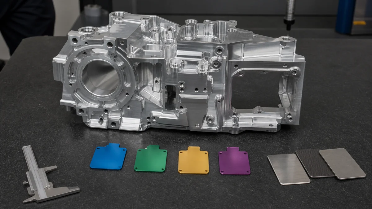
Show the classification on the controlled 2D drawing1 or in a referenced cosmetic specification. Color-coded faces, zone letters, or numbered groups can all work if the active revision and governing document are unambiguous. The 3D model helps communicate geometry, but it rarely shows whether a nominally identical face remains visible after assembly.
| Surface class | Typical part location | Required drawing controls | Suitable acceptance basis |
|---|---|---|---|
| Critical cosmetic | Customer-facing housing, bezel, or display face | Limits for scratches, dents, chatter, cutter witness marks, and clamp marks | Defined visual inspection, optionally supported by an approved limit sample |
| Functional visible | Sealing, sliding, bearing, mating, or coating-preparation face | Local Ra, dimensional tolerance, edge condition, and relevant visual limits | Measurement plus visual review where appearance also matters |
| Ordinary machined | Non-display face without a special texture function | Normal machined condition, dimensions, deburring, and general workmanship | Routine dimensional and visual inspection |
| Hidden or clamped | Internal, covered, or designated fixture-contact region | Dimensions, burr control, cleanliness, and any fixture-damage limit | Inspection focused on fit and function |
A face can carry more than one requirement. A visible sealing land, for example, needs both functional roughness2 and cosmetic protection. Write both controls instead of expecting the word “cosmetic” to protect sealing performance.
Define exceptions just as carefully. A hidden face may contain a critical datum, bore, thread, or electrical contact. A broad visible face, meanwhile, may permit uniform cutter paths when the intended industrial appearance does not justify secondary finishing. The surface-zone classification establishes where each rule applies; it should not impose the strictest rule on every marked face.
When Should Machining Marks Be Accepted or Rejected?
Accept uniform cutter paths when they match the specified as-machined condition and assigned surface zone. Reject marks when they exceed the roughness requirement or violate defined visual limits for chatter, scratches, dents, mill steps, clamp damage, or other unintended surface discontinuities.
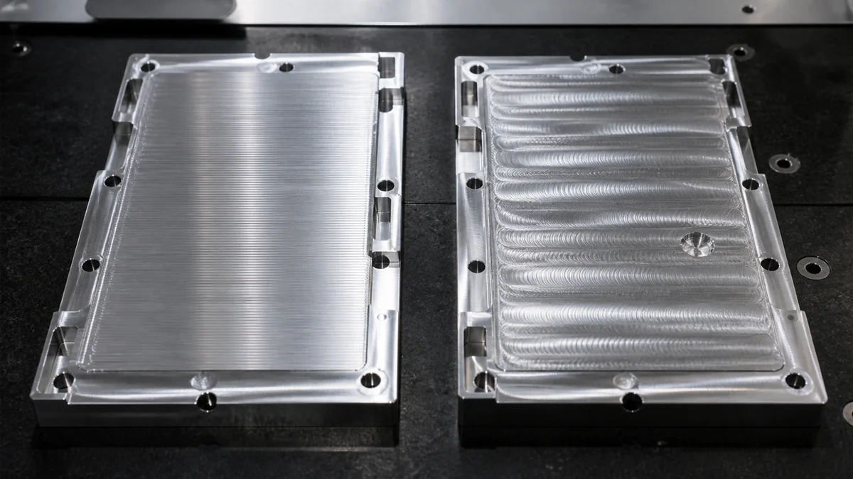
A tool mark is not automatically a defect. Milling and turning create characteristic paths as the cutting edge moves across the workpiece. The drawing must separate this expected machining texture3 from unstable cutting, setup transitions, and damage introduced during fixturing or handling.
Useful specification decisions include:
- State whether uniform, directionally consistent cutter paths are permitted.
- Identify faces where visible cutter witness marks are restricted.
- Treat chatter separately because its repeated pattern reflects vibration rather than the intended toolpath.
- Define whether mill steps or mismatched transitions between adjacent passes are acceptable.
- Restrict scratches, dents, handling damage, and clamp marks by surface zone.
- Specify burr removal and edge condition independently; a burr-free part can still retain normal machining marks.
Scenario: A machined aluminum cover meets every dimensional tolerance. Its internal pocket shows uniform circular cutter paths, while its exterior display face has one isolated clamp mark. If the pocket is ordinary machined and the display face is critical cosmetic with clamp marks prohibited, the pocket may pass while the exterior face fails. A blanket “no tool marks” note would blur that distinction and invite disagreement over both surfaces.
Defect names alone are not enough. “No scratches” becomes subjective if one inspector uses normal lighting and another searches under close oblique light. Likewise, permission for uniform tool marks cannot override a local Ra requirement on a sealing or sliding surface.
Establish a clear acceptance hierarchy: controlled drawing, referenced cosmetic specification, approved limit sample where used, and agreed inspection conditions. Resolve conflicts before production rather than after delivery.
Where Should You Apply Ra Surface Roughness Requirements?
Apply Ra requirements only where measured texture supports sealing, sliding, bearing, appearance, or coating preparation. Leave other faces at an appropriate machined condition. Ra controls average roughness, but it does not independently define tool-mark direction, isolated scratches, chatter, waviness, or overall cosmetic consistency.
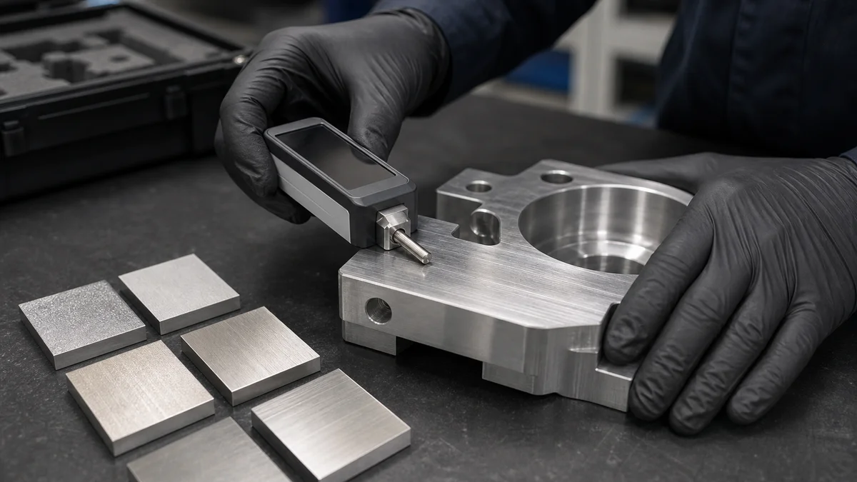
Ra is the arithmetic average roughness4 of a measured surface profile. It is useful for controlling texture, but it reduces a complex surface to one value. Two faces can have similar measured Ra results5 and still look different because their toolpath direction, spacing, isolated defects, or broader surface variation differs.
The supported values below are quoting references, not universal machining capability guarantees:
| Surface condition | Supported Ra reference | Appropriate drawing use | What still needs separate control |
|---|---|---|---|
| Ordinary CNC machined surface | Ra 3.2 µm as a common economical reference | Faces where normal machining texture suits function and appearance | Burrs, scratches, chatter, and dimensional requirements |
| Finer machined surface | Ra 1.6–0.8 µm | Local sealing, sliding, bearing, or justified cosmetic areas | Tool-mark direction, isolated defects, and visual consistency |
| Cosmetic appearance beyond roughness | No single Ra value is sufficient | Display faces or matched visible surfaces | Viewing conditions, defect limits, and approved comparison basis |
Lower Ra values may require extra finishing passes, different feed or step-over choices, closer tool-condition control, or secondary processing. The practical route depends on material grade, tool access, surface area, geometry, setup rigidity, and production intent. One open face and several deep pocket walls should not be assumed to carry the same effort simply because they share one roughness value.
Should every visible face receive an Ra callout?
No. A visible industrial face may accept a consistent normal machined texture, while a hidden sealing land may require measured roughness. Apply the value where it protects a defined functional or cosmetic outcome.
Identify the exact surface, units, measurement location where relevant, and whether acceptance applies before or after polishing, blasting, anodizing, plating, or another finish. Roughness also remains separate from size, flatness, and position.
How Should Cosmetic Surfaces Be Inspected and Approved?
Define cosmetic inspection through controlled viewing conditions, inspected zones, defect limits, sampling scope, and approval authority. State the lighting, viewing distance and direction, permitted magnification, and whether an approved limit sample governs. Keep visual approval separate from documented Ra and dimensional measurement.

Visual inspection6 becomes inconsistent when one inspector examines a part at arm’s length under normal room lighting while another uses close, angled light and magnification. The cosmetic specification should make the observation method repeatable without creating an artificial standard unrelated to how the part will be seen or used.
A practical approval plan should define:
- The drawing revision and cosmetic-zone map being inspected.
- Lighting conditions and whether the part may be rotated relative to the light.
- Viewing distance, viewing direction, and observation time where relevant.
- Whether unaided vision or specified magnification applies.
- Defects under review, such as scratches, dents, chatter, clamp marks, mill steps, stains, or inconsistent texture.
- Whether an approved golden sample7 or boundary samples supplement the written criteria.
- Inspection scope: first article, selected lot samples, every critical cosmetic face, or another agreed plan.
- Required records and the disposition route for disputed or nonconforming appearance.
Example: A first-article housing looks uniform from the defined viewing position but reveals faint cutter paths under close oblique examination. If the approved method specifies normal lighting and unaided viewing at the stated distance, close oblique examination should not silently replace it. If those paths must also be prohibited under angled light, add that condition before quotation.
Control a golden sample like other production information. Record its identity, revision, finish route, and approval status, and protect it from damage. An untracked sample can stop matching the current drawing or become a poor comparison reference over time.
Visual approval does not replace measurement. A face may look smooth while failing Ra, flatness, or dimensional tolerance. A conforming Ra reading likewise does not prove freedom from one scratch or clamp mark. Match each inspection method to the characteristic it can verify.
How Do Material and Geometry Affect Cosmetic Machining Results?
Review cosmetic expectations against the exact material grade, transparency, surface orientation, tool access, pocket depth, wall stiffness, and fixture contact. The same finish note can produce different visible results on clear plastic, opaque metal, accessible faces, recessed surfaces, or areas constrained by workholding.
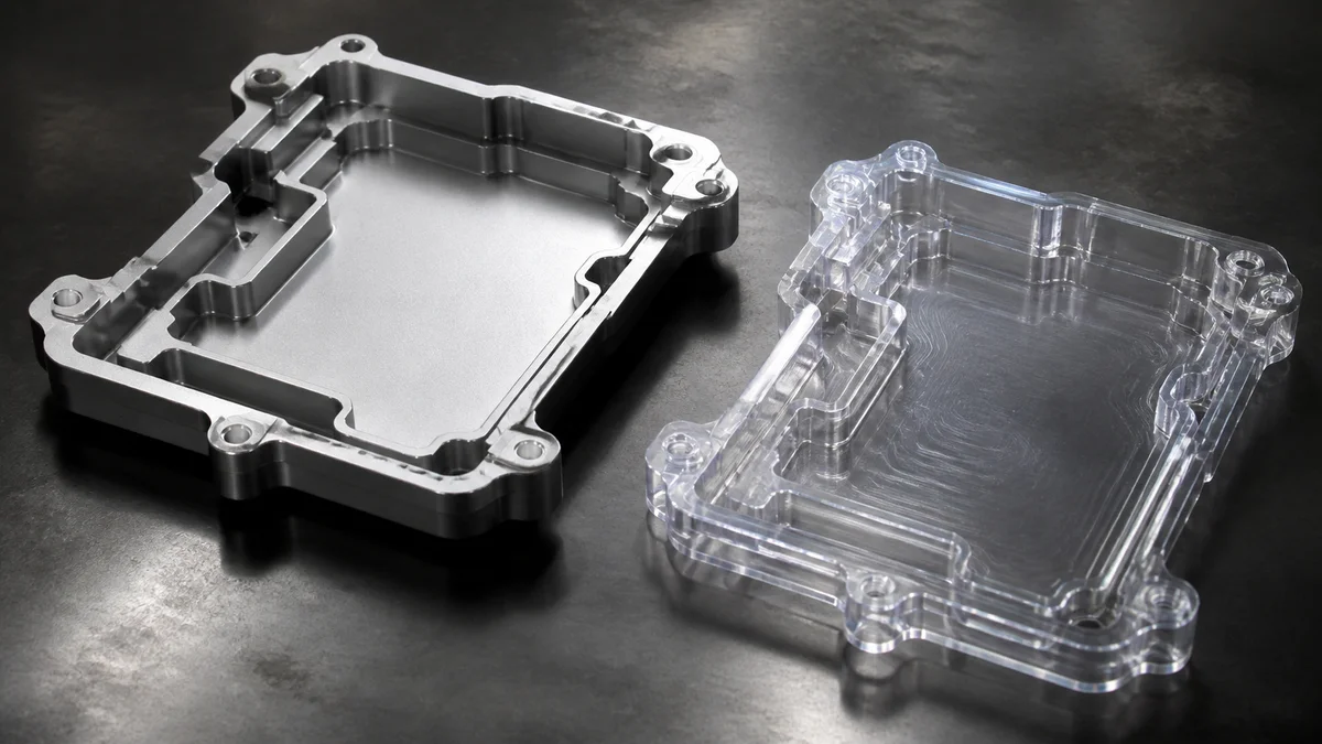
Material affects both how machining marks form and how strongly they are perceived. Opaque metal may visually soften a normal cutter pattern, while clear or transparent plastic8 can appear matte or show translucent swirl marks after machining. A dimensionally acceptable clear component should not be assumed to look optically polished unless the specified finishing route and visual standard require that result.
Geometry changes the available machining strategy. Deep pockets can require longer tooling or restricted approach angles, increasing exposure to vibration and inconsistent texture. Thin walls9 may deflect under cutting or clamping forces. Recessed faces can also be harder to polish and inspect consistently than an open exterior surface. When cosmetic faces occur on several sides, additional setups create more opportunities for fixture contact and handling marks.
Fixture access therefore belongs in the drawing discussion. Mark no-clamp surfaces and acceptable contact regions, but allow the supplier to propose the final workholding strategy. Prohibiting contact on every exterior face without providing a stable alternative can force complex fixtures, extra setups, or additional handling.
Scenario: A transparent machined cover contains a broad viewing window, a recessed internal pocket, and a perimeter flange hidden after assembly. Calling all three areas “smooth” leaves the supplier guessing. A clearer specification treats the window as a critical transparent cosmetic zone, the pocket as ordinary machined unless it remains optically visible, and the hidden flange as an allowed fixture-contact area subject to dimensional and burr requirements.
Name the exact material grade and condition rather than only “plastic,” “aluminum,” or “stainless steel.” Chip behavior, finishing response, coating compatibility, and dimensional stability depend on the actual material. Material, geometry, tolerance, finish, quantity, and inspection should be reviewed together before the route is fixed.
When Should Secondary Finishing Replace an As-Machined Cosmetic Requirement?
Choose secondary finishing when the desired uniform appearance cannot be expressed reasonably as an as-machined texture. Specify the finish as a separate operation with defined preparation, treated surfaces, masking, protected interfaces, and final inspection. Do not assume blasting, polishing, or anodizing will correct every underlying machining defect.

An as-machined requirement controls the surface left by cutting. A secondary finish intentionally changes that starting condition. The appropriate route depends on material grade, desired appearance, geometry, tolerance, functional interfaces, and the surfaces that must remain untreated.
| Finish route | Expected surface change | Required specification inputs | Dimensional concern |
|---|---|---|---|
| As machined | Retains cutter-generated texture | Surface zones, local Ra, permitted tool marks, chatter limits, and damage limits | Final cutting operation establishes the surface and size |
| Bead blasted10 | Produces a more uniform matte or satin appearance and reduces the visibility of tool marks | Coverage, cosmetic zones, masking, protected faces, and texture approval | Edge condition and protected fitted features need review |
| Polished | Reduces machining texture by removing material | Target faces, appearance or roughness, edge protection, allowance, and inspection condition | Material removal can affect size and sharp transitions |
| Anodized on suitable material | Creates a converted surface with cosmetic and protective purposes | Material, preparation, treated zones, masking, color control where required, and final inspection | Finish buildup and penetration11 can affect fitted interfaces |
Secondary finishing is not automatic surface repair. Deep chatter, dents, clamp damage, or inconsistent preparation may remain visible or produce an uneven final result. Define the acceptable starting surface separately from the required finished appearance.
Process sequence matters. Mark bores, threads, sealing lands, bearing seats, electrical contacts, and mating faces that require masking, allowance, or post-finish inspection. State whether each critical dimension applies before or after finishing so the machinist, finisher, and inspector use the same acceptance basis.
For a prototype, decide whether the finish must validate appearance or whether an as-machined part is sufficient for fit and function. For production, define whether the first finished article needs approval before the remaining lot proceeds. That separates machining acceptance, finish acceptance, and dimensional acceptance without disconnecting them.
Which Cosmetic Requirements Increase Cost and Lead Time?
Cost and schedule rise when cosmetic requirements demand finer machining, larger controlled areas, extra setups, secondary processing, masking, protected handling, or documented inspection. Localize each requirement to the surfaces that justify it, and define production and approval scope before suppliers estimate the complete manufacturing route.

Cosmetic requirements influence much more than the final toolpath. They can change cutter selection, finishing passes, setup orientation, fixture design, deburring, handling, outside processing, inspection, packaging, and the timing of first-article approval.
The main quotation drivers are diagnostic rather than cosmetic labels:
- Controlled area: One accessible display face is different from pockets, side walls, and surfaces spread across several orientations.
- Roughness level: Finer Ra values may require extra passes and closer control of tooling and process conditions.
- Tool-mark limits: A zero-mark expectation may require polishing or another secondary finish rather than ordinary cutting.
- Tool access and setup count12: Recessed or multi-side cosmetic faces can require longer tools, reclamping, or additional orientations, increasing fixture-contact risk.
- Material grade: Chip formation, cutting response, and finishing behavior vary with material and condition.
- Secondary routing: Blasting, polishing, anodizing, plating, masking, cleaning, transport, and final handling are separate operations.
- Inspection scope13: Visual review, roughness readings, first-article records, lot sampling, or inspection of every cosmetic face consumes production and reporting time.
- Production intent: A learning prototype, appearance sample, pilot lot, and repeat order may need different approval and process-control plans.
A common specification mistake is applying “Ra 0.8 µm, no visible tool marks” to the entire part, including hidden pockets and designated fixture faces. That note broadens finishing and inspection beyond the customer-facing need. Another mistake is requesting a uniform appearance without identifying the finish route, causing suppliers to quote different delivered conditions.
Ask each supplier to state the assumed machined condition, secondary finish, masking, inspection scope, and geometry-related handling risks. Comparable quotations require a common acceptance basis rather than competing interpretations of “cosmetic quality.”
What Should a Cosmetic-Surface RFQ Include?
A cosmetic-surface RFQ should identify CNC machining as the intended process and provide the model, controlled drawing, material, quantity, production intent, surface zones, acceptable marks, local roughness, secondary finishes, tolerances, inspection method, revision, and delivery expectations. Resolve conflicting files and ambiguous process names before quotation.
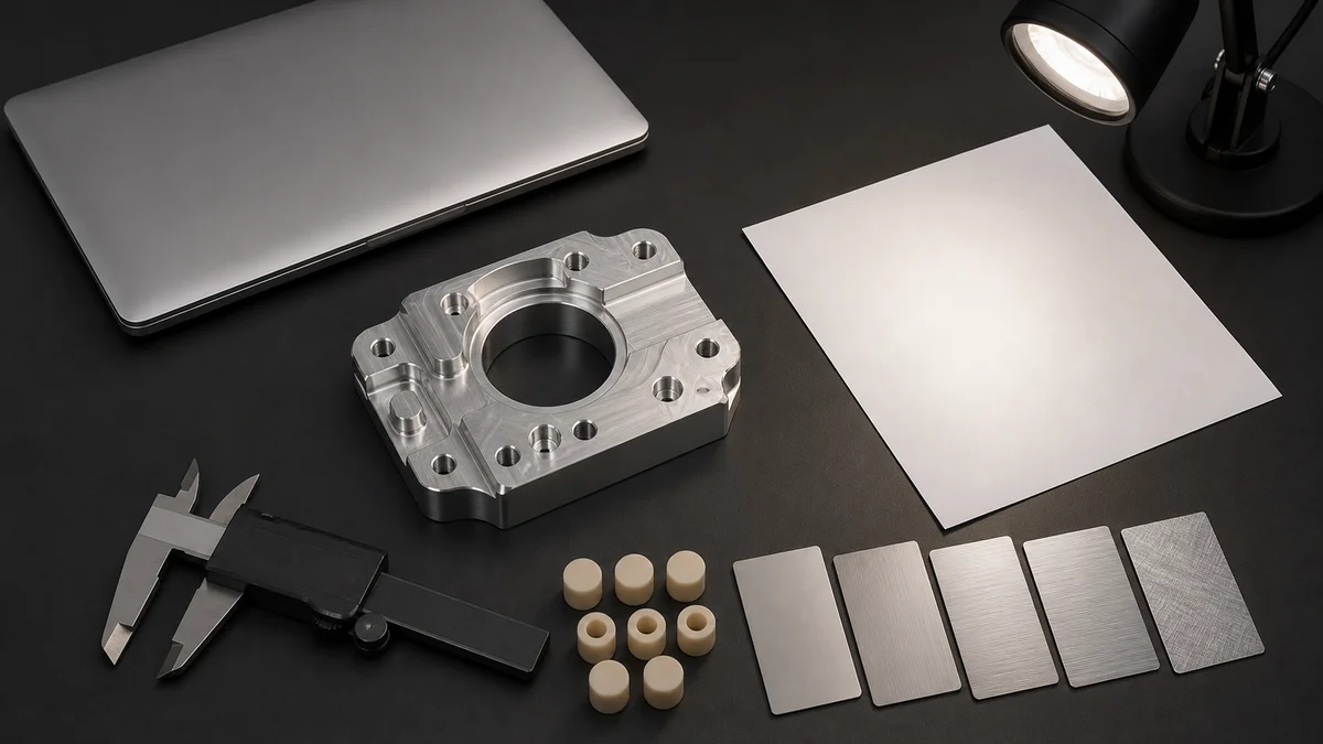
Use the RFQ to connect appearance requirements to the complete manufacturing plan. The 3D model communicates geometry, while the controlled 2D drawing should govern surface zones, tolerances, finish symbols, notes, and inspection requirements unless another document is explicitly designated.
Cosmetic-surface RFQ and approval checklist
- ☐ Matching 3D model and controlled 2D drawing
- ☐ Part number, units, active revision, and governing document if the files conflict
- ☐ Exact material grade, temper, condition, and permitted alternatives
- ☐ Immediate quantity and prototype, appearance-sample, pilot, or repeat-production intent
- ☐ Critical cosmetic, functional visible, ordinary machined, and hidden or clamped zones
- ☐ Permitted cutter paths and prohibited chatter, scratches, dents, mill steps, or clamp marks
- ☐ Local Ra requirements with identified faces and units
- ☐ Deburring, edge condition, cleanliness, burr direction where relevant, and protected no-clamp areas
- ☐ Secondary finish, preparation, treated faces, masking, and untreated interfaces
- ☐ Statement of whether critical dimensions apply before or after finishing
- ☐ Visual inspection conditions, approved limit sample where used, and approval authority
- ☐ Roughness and dimensional measurement requirements with reporting scope
- ☐ First-article, sampling, or production-lot inspection expectations
- ☐ Delivery expectations and required approval timing before the remaining lot proceeds
Name the manufacturing process correctly. CNC machining removes material from solid stock14 by milling, turning, drilling, boring, reaming, or related operations. CNC turret punching15 and a CNC punch press use programmed punch tools on sheet metal. Metal stamping uses dedicated dies. Sheet metal fabrication may combine cutting, punching, bending, welding, hardware insertion, and finishing. Plastic injection molding forms polymer in a mold.
“CNC turret punching, CNC punch press, CNC-controlled stamping equipment, or metal stamping depending on the actual process” is not one standard process term. It might refer to CNC turret punching, a CNC punch press, CNC-controlled stamping equipment, or general metal stamping. Clarify the intended operation, stock form, geometry, and tooling model before discussing cosmetic acceptance or comparing quotations.
For a process recommendation, appearance sample, or quotation, send the 3D model, controlled 2D drawing, material grade, quantity, prototype or production intent, critical tolerances, cosmetic-zone map, local Ra values, secondary finish, inspection expectations, active revision, and delivery requirements.
References
-
Surface Roughness Symbols: Drawing Examples & ISO ... - Learn how to read surface roughness symbols on engineering drawings, understand ISO 1302 standards, surface finish callouts, and Ra values. ↩
-
Surface Roughness Guide: Ra Rz, ISO 21920 & Mitutoyo ... - Surface roughness is the micro-geometry of an engineering surface. It controls how a sealing surface seals, how a sliding bearing wears, ↩
-
What are the types of surface finishes for CNC machining? - As-machined parts show minor visible tool marks. The standard surface roughness (Ra) is 3.2 μm, with tighter options of 1.6, 0.8, and 0.4 μm available. Bead ... ↩
-
Surface Roughness Average (Ra): Chart, Formula, and ... - Ra (Roughness Average) is the arithmetic average of the absolute values of a surface's microscopic peaks and valleys, measured from the mean ... ↩
-
ASME B46.1-2009 Surface Texture (Surface Roughness ... - Limits for the Transmission … cutoff ratios are 100, 300, or domain. The stylus dimensions limit the minimum size of the irregularities which are included in a ... ↩
-
ASTM Standards for Glass: When is a Defect Not a Defect? - Inspection should not exceed viewing of more than 5 seconds for lites up to 6 square feet, 10 seconds for lites up to 35 sq ft, and 20 seconds ... ↩
-
Should I use a Golden Sample or Limit Samples? - If your product or component has no variation, then a golden sample can be used during inspection to simply pass or fail it with a yes/no ... ↩
-
Vapor Polishing for Plastics: Process, Materials, and Uses - Vapor polishing is a chemical surface finish process in machining. It is primarily used on thermoplastic parts where solvent vapor slightly ... ↩
-
Working with Thin-Walled Parts in CNC Machining | Blog - Thin-walled parts are more prone to vibration and chatter because of their reduced stiffness. These vibrations can cause poor surface finishes, inaccurate cuts ... ↩
-
Bead Blasting: What It Is and How to Design CNC Parts for It - Bead blasting creates a uniform, non-reflective satin texture that effectively hides tool marks on CNC machining parts. ↩
-
How Anodizing Affects Dimensions | Build-Up vs Penetration - Learn how anodizing changes aluminum part dimensions, including the critical difference between build-up and penetration for Type I, Type II, and Type III ... ↩
-
CNC Machining Cost: Pricing & Savings Guide 2026 - uneed - Reduce CNC machining cost by reducing setup count, improving tool access, standardizing features, and tightening tolerances only where function needs them. ↩
-
Understanding First Article Inspection in Manufacturing - First article inspection verifies that the first part produced meets design specifications before full production begins, ensuring quality from the start. ↩
-
Subtractive Manufacturing: Key Facts You Should Know - CNC machining is one of the most popular methods in subtractive manufacturing. CNC machines can perform milling, turning, drilling, and grinding operations ↩
-
Metal Punching & Stamping: What You Need to Know - CNC turret punch presses. Metal punching removes material to create holes or openings in sheet metal. Metal stamping reshapes sheet metal into complex parts ↩