
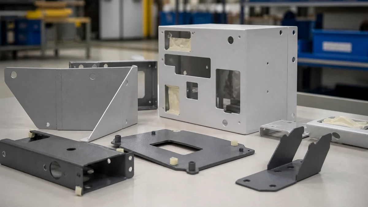
Powder coating specifications often begin with a color note, but color alone does not define a manufacturable or inspectable finish. The supplier also needs the service environment, substrate condition, pretreatment, film build, masking boundaries, part geometry, final dimensional requirements, cure basis, and acceptance criteria.
These decisions interact. A coating system suitable for a dry indoor enclosure may not fit outdoor corrosive exposure. A visually acceptable film can still obstruct a thread, reduce slot clearance, or cover a grounding point. Formed sheet metal also carries variation from cutting, bending, springback, welding, and hardware installation.
A useful specification therefore moves in a deliberate order: service conditions, substrate preparation, coating access, film build, dimensional control, appearance, inspection, curing, and the final RFQ package.
What Service Environment Should the Powder Coating Withstand?
Define the operating environment and durability objective before selecting color, powder chemistry, or pretreatment. State whether the part will be used indoors or outdoors and describe relevant humidity, salt, chemicals, cleaning practices, weather exposure, and expected service conditions.
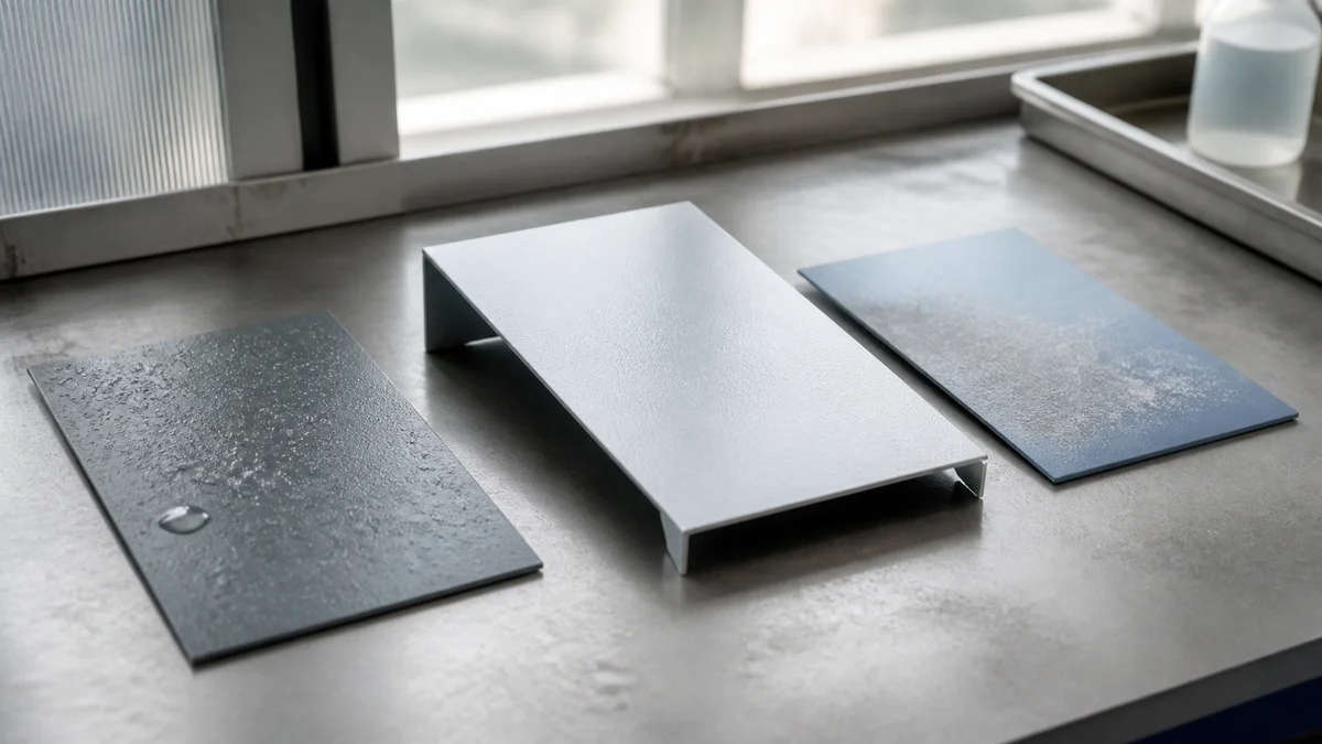
Powder coating is a cured protective and decorative finish applied over a prepared metal substrate. Its suitability depends on the complete coating system, including surface preparation and pretreatment, not merely the visible powder layer.
Replace broad notes such as “weather-resistant” with an exposure description the supplier can evaluate. State whether the part is sheltered, exposed to rain, located near salt, cleaned with chemicals, or subject to condensation or persistent humidity. When ISO 12944-2 corrosivity categories1 are applicable to the project, identify the engineering-selected category and durability band rather than asking the coater to infer them.
| Service variable | RFQ information | Specification consequence |
|---|---|---|
| Installation | Indoor, outdoor, sheltered, or fully exposed | Establishes the basic coating-system review |
| Moisture | Humidity, condensation, washdown, or immersion risk | Influences pretreatment and corrosion planning |
| Salt or chemicals | Source, concentration if known, contact frequency, and cleaners | Guides substrate and powder compatibility review |
| Maintenance | Cleaning method and expected frequency | Helps prevent incompatible maintenance assumptions |
| Appearance | Primary cosmetic zones and exposure to weathering | Connects durability with visual acceptance |
| Governing durability basis | Project category, band, or written service requirement | Gives the supplier a defined selection target |
A familiar RAL color does not establish environmental performance. The same color may be available in coating systems intended for different substrates and exposures. Review color only after the service environment, substrate, pretreatment, geometry, and maintenance conditions are clear.
What Pretreatment Should Be Specified for the Substrate?
Specify pretreatment from the exact substrate and its incoming condition. Aluminum, ferrous steel, galvanized steel, magnesium, and previously finished parts can require different preparation, while oil, corrosion, mill scale, weld spatter, and surface damage must be addressed before coating.
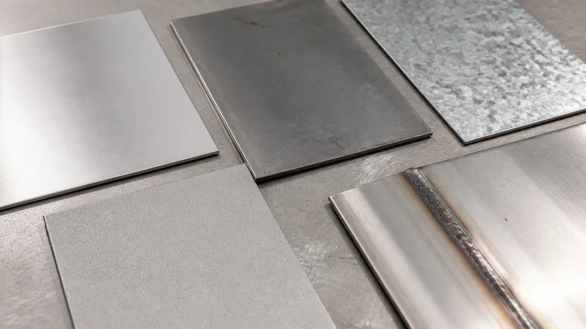
Pretreatment establishes the surface condition needed by the selected coating system. Do not bury it inside a note such as “powder coat after fabrication.” The RFQ should name the material grade and explain whether parts reach the coater blanked, bent, welded, galvanized, blasted, or previously finished.
If engineering has approved a route, state it directly. Supported examples include phosphate pretreatment2 and sand or media blasting. If no route has been selected, define the incoming condition, required finished condition, and exposure, then request a compatible process recommendation.
The pre-coat review should address:
- Base metal, material grade, sheet gauge, and any galvanizing or conversion layer.
- Oil, coolant, drawing compound, fingerprints, and other fabrication residue.
- Rust, corrosion, mill scale, pits, scratches, and embedded debris.
- Weld spatter, sharp projections, heat discoloration, and incomplete weld cleanup.
- Existing paint, plating, blasting, polishing, or another surface treatment.
- Cosmetic faces and dimensions that must remain controlled after preparation.
Surface cleaning and cosmetic correction are not the same operation. Removing contamination does not automatically remove dents, pits, scratches, uneven welds, or grind marks. Abrasive preparation can also alter texture, so the drawing should identify visible faces before the supplier selects the preparation sequence.
Common mistake: expecting the cured coating to hide poor substrate quality. Powder generally follows the underlying topography. Acceptance criteria should distinguish fabrication defects, surface conditions remaining after pretreatment, and defects introduced during coating.
Does the Part Geometry Allow Hanging, Venting, and Spray Access?
Review every part for a usable hanging point, acceptable rack-mark location, spray access, and a path for excess powder and air to escape. Closed sections, deep pockets, narrow gaps, obstructed faces, and small openings require coating-specific design review.
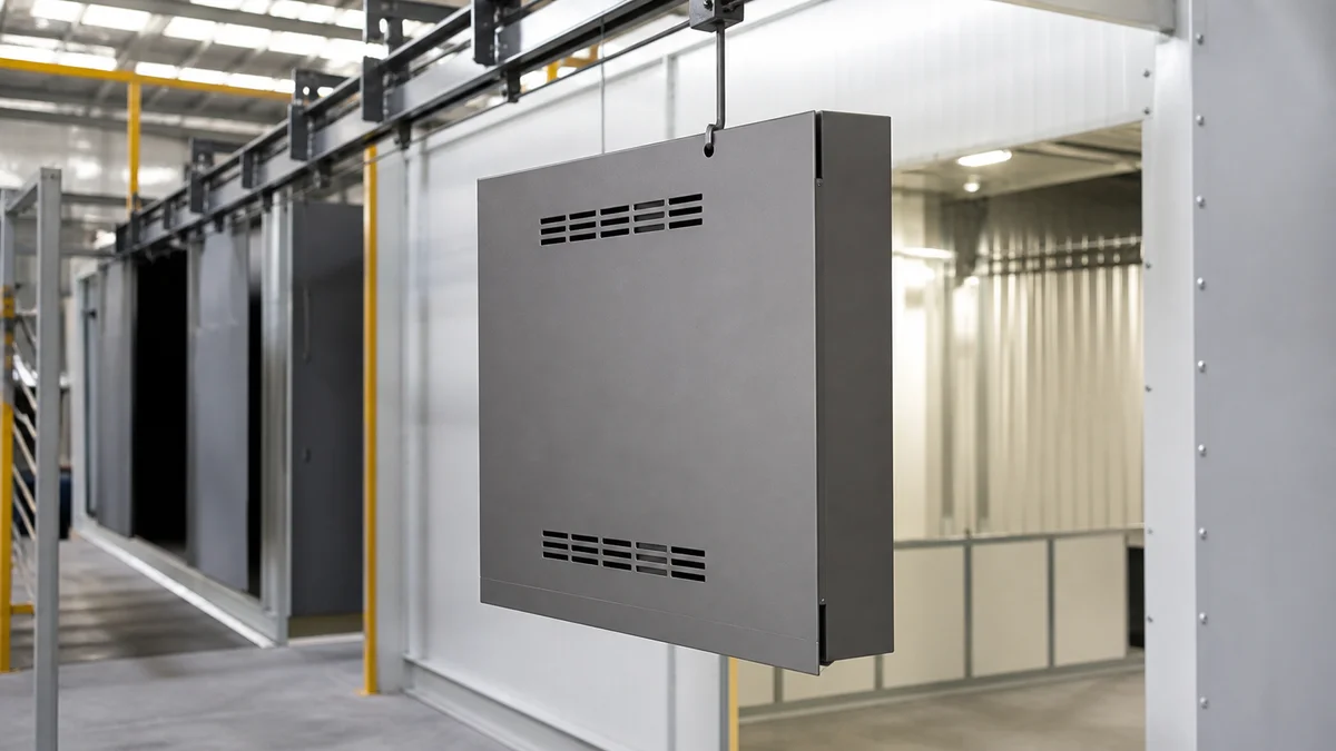
A part can be straightforward to cut and bend yet awkward to coat. The coater must support it, maintain electrical contact during application, reach required surfaces, and prevent excess powder from collecting in enclosed geometry. Those needs can conflict with cosmetic and assembly features unless they are resolved before release.
Review the design for:
- A hole, cutout, edge, or approved feature that can support hanging and electrical contact.
- Rack marks located away from visible, sealing, grounding, and mating surfaces.
- Vent openings that allow air and excess powder to leave closed or partly enclosed sections.
- Spray access to internal corners, returns, hems, deep pockets, and closely spaced flanges.
- Small holes, slots, threads, and cutouts that must remain open after coating.
- Orientations that could encourage trapped powder or uneven buildup.
Supplier guidance may include minimum dimensions for hanging holes3 or small features, but those limits depend on fixtures and process practice. Put functional requirements on the drawing and confirm manufacturing details with the selected coater rather than converting one supplier’s guideline into a universal design rule.
Scenario: A folded enclosure has no hidden hanging point, and every exterior face is cosmetic. The coater may need to contact a visible edge or request a temporary or redesigned feature. Without an approved rack-mark location, an otherwise uniform enclosure can still fail cosmetic acceptance.
Complete this review before nesting and bend release. Moving a vent or hanging hole later can alter edge distance, bend clearance, burr direction, cosmetic zoning, and assembly fit.
How Should Film Build and Masking Zones Be Defined?
State the required film build in microns or mils, identify the surfaces where it applies, and mark every interface that must remain uncoated. Dimensions, threads, fits, contacts, sealing lands, holes, and narrow gaps should be reviewed in their finished condition.
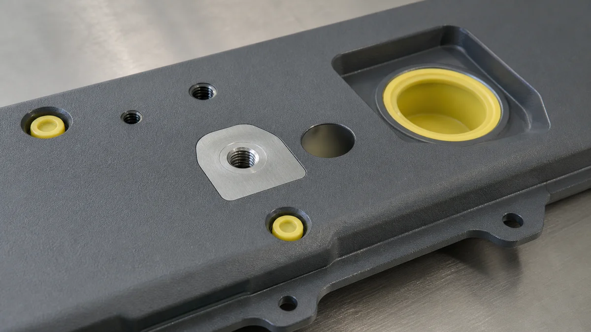
Film build is both a finish requirement and a dimensional input. Powder adds material to each exposed surface, with local buildup possible around edges, openings, recesses, and closely spaced geometry. The approved powder system and supplier should establish an appropriate range; there is no single thickness suitable for every substrate, environment, or part.
A masking drawing4 is more useful than a general instruction because it fixes boundaries, transition zones, and the required condition of each interface.
| Feature | Required drawing decision | Practical consequence |
|---|---|---|
| Internal thread | Mask, coat, or define final thread acceptance | Buildup can reduce usable clearance |
| Press-fit or locating surface | Protect or compensate dimensionally | Added film can prevent assembly |
| Grounding point | Keep uncoated where conductivity is required | Coating can interrupt electrical contact |
| Sealing land | Define coverage and final surface condition | Buildup can change contact pressure or sealing geometry |
| Slot or small hole | State the finished opening requirement | Coating on opposing sides reduces clearance |
| Cosmetic face | Define coverage and masking transition | Ambiguous boundaries create visual disputes |
| Rack location | Approve the contact zone | Hanging can leave a local witness mark |
State whether critical dimensions apply before or after coating. A pre-coat dimension may control fabrication, while a post-coat requirement governs assembly. If both conditions matter, call them out without duplicating or conflicting tolerances.
Avoid “mask all critical areas.” The phrase asks the supplier to decide what the design considers critical. Mark each protected surface and connect it to fit, sealing, conductivity, appearance, or inspection.
Which Dimensions Must Be Controlled After Powder Coating?
Control post-coat dimensions only where the finished feature affects fit, alignment, sealing, clearance, or assembly. Separate coating buildup from sheet-forming variation, identify critical interfaces, and define which holes, slots, gaps, edges, and bend-related dimensions require final inspection.
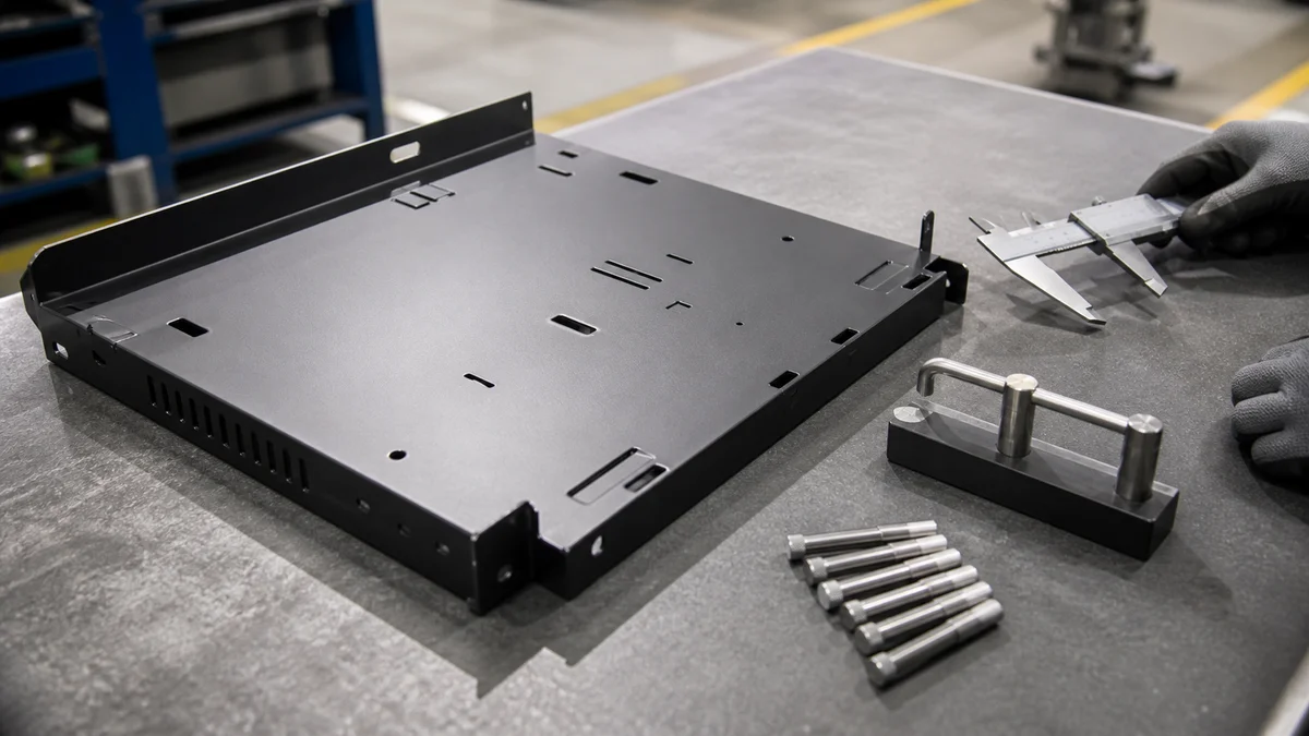
Powder can reduce openings and increase external dimensions, but coating buildup is only one contributor to final variation. Sheet metal parts can also accumulate tolerance through cutting, hole placement, bend position, bend angle, springback, welding, hardware insertion, and relationships across several bends.
Organize dimensions by function:
- Finished functional dimensions: Mating gaps, mounting slots, locating holes, grounding interfaces, and other features that must conform after coating.
- Pre-coat fabrication dimensions: Requirements used to control cutting, CNC turret punching, bending, welding, or hardware installation before finishing.
- Non-critical geometry: Features adequately covered by general drawing tolerances and coating workmanship.
A dimension crossing several formed faces may be driven mainly by bend sequence and springback5. By contrast, a small hole or narrow slot may be stable after forming but lose clearance when coating covers opposing surfaces. Tightening every profile dimension does not solve either problem; the drawing must identify the actual functional condition.
Example: A removable panel has two coated slots that fit over fixed studs. If the slots are controlled only before coating, film on both edges can consume assembly clearance. Specify the finished slot requirement, indicate whether masking is acceptable, and request post-coat inspection when the fit is critical.
Ask the fabricator and coater to review the same controlled revision. That keeps bend assumptions, masking, film build, and inspection aligned while avoiding close post-finish tolerances on unrelated edges and cosmetic faces.
How Should Color, Gloss, Texture, and Cosmetic Quality Be Specified?
Define appearance with a color reference, gloss range, texture, film build, cosmetic zones, comparison basis, rack-mark limits, and defect criteria. A color name alone cannot establish surface texture, reflectivity, visual uniformity, acceptable variation, or the treatment of visible defects.
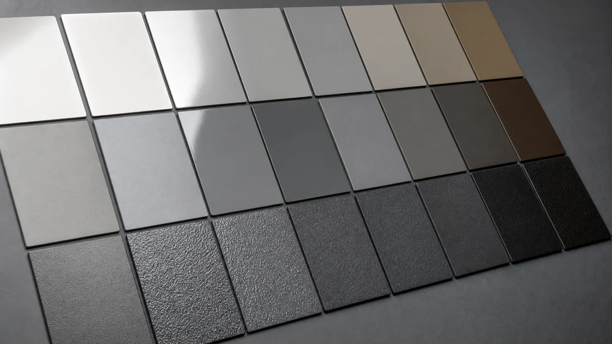
Appearance is a group of controlled attributes, not a single color selection. A RAL code6 or approved sample communicates color intent, while gloss and texture establish how the surface reflects light and presents fabrication variation. Pretreatment and film build can also influence the visible result.
| Appearance control | Information to place in the drawing or RFQ | Acceptance purpose |
|---|---|---|
| Color | Applicable code or controlled comparison sample | Establishes the intended hue |
| Gloss | Required range or approved finish designation | Controls reflectivity |
| Texture | Smooth, textured, or another defined condition | Establishes surface character |
| Primary cosmetic zones | Exposed faces and viewing priority | Focuses the strictest visual review |
| Secondary or hidden zones | Surfaces partly or fully concealed after assembly | Prevents blanket cosmetic requirements |
| Rack marks | Permitted locations and limits | Controls visible contact evidence |
| Defects | Rejectable gaps, debris, runs, sags, scratches, pinholes, cissing, or inclusions | Defines objective rejection categories |
| Rework | Prohibited, permitted, or subject to approval | Prevents unapproved touch-up |
If the finish must match another component, provide a controlled comparison basis. Terms such as “standard black,” “semi-gloss,” and “match existing” leave color, gloss, texture, and viewing conditions open to interpretation.
Surface preparation remains part of cosmetic planning. Powder should not be expected to hide pits, scratches, uneven blasting, weld marks, or grind patterns. Mark visible surfaces before deburring, welding, grinding, and pretreatment so each operation follows the same priorities.
Common mistake: applying premium cosmetic acceptance to every surface. Separate primary display faces, secondary visible faces, and hidden functional areas instead.
What Inspection and Acceptance Evidence Should the RFQ Require?
Define inspection before quotation by identifying inspected surfaces, rejectable defects, coating-thickness checks, critical post-coat dimensions, adhesion requirements, sampling, reporting, and first-article approval. Also state the cosmetic review condition and who may authorize touch-up, rework, or deviation.

“Inspect powder coating” is not an acceptance plan. Visual condition, film thickness, adhesion, and dimensional conformance are separate characteristics that may need different methods, frequencies, and records.
Use an approval checklist that answers these questions:
- Which cosmetic zones are reviewed, and under what agreed viewing condition?
- Which defects are rejectable: coverage gaps, debris, runs, sags, scratches, pinholes, cissing, inclusions, or another stated condition?
- Is film thickness measured, and at which named surfaces or zones?
- Which holes, slots, mating interfaces, or bend-related dimensions require post-coat results?
- Does an adhesion test7 govern acceptance? If so, which method and required result apply?
- Is inspection limited to a first article, based on batch sampling, or repeated for every production lot?
- What report format, part number, drawing revision, and lot reference must accompany delivery?
- Is touch-up allowed, and who can approve rework or deviation?
Match the inspection method to feature risk. Visual review may be sufficient for general appearance, while coating thickness and dimensional requirements need recorded values at defined locations. Avoid requiring one method for every characteristic when geometry, access, tolerance, inspection level, or production intent calls for a different approach.
First-article approval confirms only the inspected sample against the stated requirements. It does not establish continuing conformance for later production. If ongoing evidence is needed, specify the sampling frequency, lot identification, and report content separately.
Unclear inspection scope creates quotation gaps because the supplier must estimate measurement time, documentation effort, handling, and rejection exposure.
Who Should Define the Powder-Coating Cure Schedule?
The approved powder system and coating supplier should define the supported cure schedule unless the project has a validated governing requirement. Cure depends on powder chemistry, substrate temperature, part mass, geometry, loading, and oven conditions, not one generic time-and-temperature note.
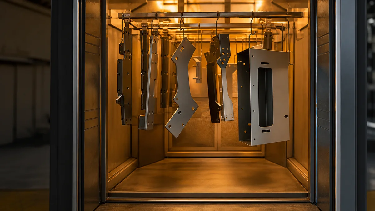
Curing converts deposited powder into the finished film. The required condition depends on more than the displayed oven temperature. Substrate temperature, material thickness, part mass, geometry, rack loading, and heat distribution influence how the workpiece reaches and holds the supported cure condition8.
Do not copy a generic time-and-temperature note from another drawing. Different powder systems can require different schedules, and nominally similar parts can heat differently. A light open bracket does not present the same thermal behavior as a welded enclosure with reinforced or mixed-thickness regions.
A clear finish specification can:
- Identify the approved powder manufacturer and product code when these are controlled.
- Define the approval route for any proposed substitute.
- Require processing according to the selected system’s supported instructions.
- Flag heavy sections, enclosed regions, mixed thicknesses, and unusual thermal mass.
- Identify inserts, masking materials, adhesives, or assembled components that may be heat-sensitive.
- State required process or inspection evidence without inventing an oven setting.
Example: A legacy drawing specifies one fixed oven time, but the revised assembly adds welded reinforcement and changes sheet gauge. Retaining the old note may conflict with the approved powder system or ignore the time needed for the actual substrate to reach temperature. The better approach is to control the coating system and final acceptance requirements, then let the coater establish a supported process for the current geometry.
Curing can also affect batch loading, masking selection, inspection, and production scheduling. Include these conditions during quotation rather than resolving them after finish approval.
What Should a Powder-Coating RFQ Include?
A powder-coating RFQ should combine controlled part data, sheet metal process information, substrate details, environmental requirements, finish attributes, masking, final tolerances, inspection, quantity, revision, and delivery expectations. Complete inputs let fabrication and coating suppliers quote the same finished condition.
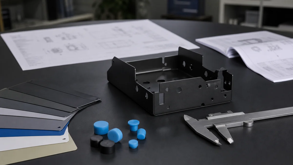
Use one controlled package for fabrication and coating. The 3D model communicates geometry; the 2D drawing controls material, gauge, tolerances, finish zones, masking, inspection, and revision-specific requirements. If the files conflict, state which document governs before requesting a quotation.
Powder-coating RFQ checklist
- ☐ Current 3D model and controlled 2D drawing.
- ☐ Part number, units, active revision, and governing document.
- ☐ Exact material grade, condition, sheet gauge, and substrate treatment.
- ☐ Immediate quantity and prototype, pilot, or repeat-production intent.
- ☐ Expected lot pattern or annual demand when known.
- ☐ Cutting, punching, bending, welding, hardware, and required assembly state.
- ☐ Critical pre-coat and post-coat tolerances.
- ☐ Service environment, cleaning exposure, and durability objective.
- ☐ Required pretreatment or permission for a supplier recommendation.
- ☐ Approved powder system, product code, and substitution rules when applicable.
- ☐ Color reference, gloss, texture, film build, and cosmetic zones.
- ☐ Masking boundaries, grounding points, threads, fits, seals, and protected openings.
- ☐ Hanging locations, venting, spray access, and acceptable rack marks.
- ☐ Visual defects, thickness checks, adhesion requirements, and dimensional inspection.
- ☐ First-article, sampling, report, rework, and approval requirements.
- ☐ Maintenance instructions and delivery expectations.
Name the manufacturing route correctly. Sheet metal fabrication may include cutting, bending, CNC turret punching9, welding, hardware installation, and finishing. A CNC punch press uses programmed tools on sheet. Metal stamping uses dedicated dies. CNC machining removes material from solid stock, while plastic injection molding forms polymer in a mold.
“CNC turret punching, CNC punch press, CNC-controlled stamping equipment, or metal stamping depending on the actual process” is not one standard process term. Clarify whether it means CNC turret punching, a CNC punch press, CNC-controlled stamping equipment, or general metal stamping before quotation.
For a coating recommendation, sample review, or quotation, send the 3D model, controlled 2D drawing, material grade, sheet gauge, quantity, prototype or production intent, service environment, critical tolerances, surface finish, masking plan, inspection expectations, revision level, and delivery requirements. Identify the approved powder system or permitted alternatives when applicable.
References
-
ISO 12944-2:1998(en), Paints and varnishes - defines atmospheric-corrosivity categories, based on mass loss (or thickness loss) by standard specimens, and describes typical natural atmospheric ... ↩
-
Types of Powder Coating Pretreatments - Adding any sort of phosphate stage to your pretreatment process means enhancing the performance attributes and quality of your work for the ... ↩
-
6 DFM Tips, Powder Coated Sheet Metal (Updated for 2025) - If your part requires powder coating and your design doesn't already have holes, we recommend designing a 0.125” diameter hole in an ... ↩
-
How to Mask Parts for Powder Coating: Tapes, Plugs, Caps ... - Complete guide to masking for powder coating including high-temp tapes, silicone plugs, caps, liquid masks, and custom tooling for complex ... ↩
-
A preliminary guide for the sheet metal bending tolerances - A preliminary guide for the sheet metal bending tolerances. Bent dimensions: ±0.25 to ±2mm (less accurate) This post will briefly explain where the variations ... ↩
-
RAL Color System Powder Collection - Shop the RAL color system powder coat collection. Find the right RAL powder coating products for your job. Free RAL color samples available. ↩
-
Standard Test Methods for Rating Adhesion by Tape Test - These test methods cover procedures for assessing the adhesion of relatively ductile coating films to metallic substrates by applying and removing pressure- ... ↩
-
Powder Coating Curing Temperatures: Complete Guide - Standard thermosetting powders require a substrate temperature of 325°F–400°F (163°C–204°C), typically cure within a substrate temperature ... ↩
-
CNC Turret Punch Guide: Process, DFM, Cost vs Laser - CNC turret punching is a sheet metal fabrication process that produces holes, slots, cutouts, and formed features in flat sheet using a CNC- ... ↩